Transcription
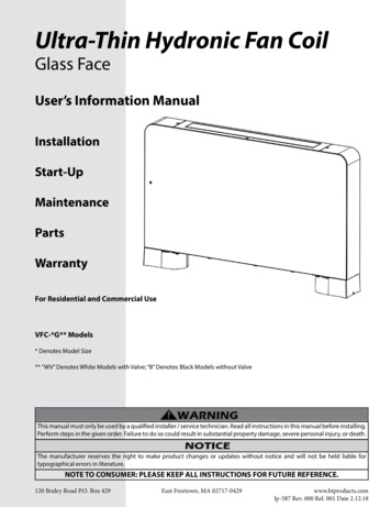
Ultra-Thin Hydronic Fan CoilGlass FaceUser’s Information For Residential and Commercial UseVFC-*G** Models* Denotes Model Size** ”WV” Denotes White Models with Valve; “B” Denotes Black Models without ValveThis manual must only be used by a qualified installer / service technician. Read all instructions in this manual before installing.Perform steps in the given order. Failure to do so could result in substantial property damage, severe personal injury, or death.The manufacturer reserves the right to make product changes or updates without notice and will not be held liable fortypographical errors in literature.NOTE TO CONSUMER: PLEASE KEEP ALL INSTRUCTIONS FOR FUTURE REFERENCE.120 Braley Road P.O. Box 429East Freetown, MA 02717-0429www.htproducts.comlp-587 Rev. 000 Rel. 001 Date 2.12.18
2Table of ContentsPart 1 - General Safety InformationThe following defined terms are used throughout this manual toA. When Servicing the Water Heating Systembring attention to the presence of hazards of various risk levels or toB. System Waterimportant product information.C. Freeze ProtectionD. NotesE. Fundamental Safety RulesDANGER indicates an imminently hazardous situation which, if not Part 2 - Prepare the Fan Coilavoided, will result in serious personal injury or death.A. Included with the Fan CoilB. Locating the Fan CoilC. Water Chemistry RequirementsWARNING indicates a potentially hazardous situation which, if notD. Information and Recommendationsavoided, could result in personal injury or death.Part 3 - Technical SpecificationsA. SpecificationsB. DimensionsC. Description of OperationCAUTION indicates a potentially hazardous situation which, if notPart 4 - Installationavoided, may result in moderate or minor personal injury.A. PrecautionsB. Positioning the Fan CoilC. MountingCAUTION used without the safety alert symbol indicates aD. Water Pipingpotentially hazardous situation which, if not avoided, may result inE. Condensate Pipingproperty damage.F. PurgingPart 5 - OperationA. Control DescriptionNOTICE is used to address practices not related to personal injury.B. Using the DisplayC. Remote Control (Optional) DescriptionForewordD. Using the Remote ControlThis manual is intended to be used in conjunction with other literatureE. Default Settingsprovided with the fan coil. This includes all related control information.F. Parameter ListIt is important that this manual, all other documents included in Part 6 - Maintenance and Troubleshootingthis system, and additional publications including the Code for theA. CleaningInstallation of Heat Producing Appliances (latest version), be reviewed inB. Common Faults and Solutionstheir entirety before beginning any work.Part 7 - WiringLimited Five (5) Year WarrantyInstallation should be made in accordance with the regulations ofCustomer Installation Record Formthe Authority Having Jurisdiction, local code authorities, and utilitycompanies which pertain to this type of water heating equipment.Authority Having Jurisdiction (AHJ) – The AHJ may be a federal, state,local government, or individual such as a fire chief, fire marshal, chiefof a fire prevention bureau, labor department or health department,building official or electrical inspector, or others having statutoryauthority. In some circumstances, the property owner or his/her agentassumes the role, and at government installations, the commandingofficer or departmental official may be the AHJ.NOTE: The manufacturer reserves the right to modify product technicalspecifications and components without prior notice.For the InstallerThis fan coil must be installed by qualified and licensed personnel. Theinstaller should be guided by the instructions furnished with the fancoil, and by local codes and utility company requirements.Installations Must Comply With:Local, state, provincial, and national codes, laws, regulations, andordinances.Code for the Installation of Heat Producing Appliances (latest version)from American Insurance Association, 85 John Street, New York, NY11038.The latest version of the National Electrical Code, NFPA No. 70.lp-587 Rev. 000 Rel. 001 Date 8182224Part 1 - General Safety InformationThis fan coil is approved for indoor installations only. Clearances:6” top, 3.54” bottom, 1” sides, 16” front, and 0” back. This fan coilhas been approved for installation on combustible flooring. Installthe fan coil in a location where a leak will not result in damage tothe surrounding area. If such a location is not available, install anauxiliary catch pan.Installer - Read all instructions in this manual before installing.Perform steps in the given order.User - This manual is for use only by a qualified heating installer /service technician. Have this fan coil serviced / inspected annuallyby a qualified service technician.NOTE: Obey all local codes. Obtain all applicable permits beforeinstalling the fan coil.NOTE: Install all system components and piping in such a mannerthat does not reduce the performance of any fire rated assembly.Ensure the fan coil is properly grounded.NOTE: If the fan coil is exposed to the following, do not operate.Immediately call a qualified service technician.1. Fire2. Damage3. WaterFailure to adhere to these guidelines can result in substantialproperty damage, electric shock, severe personal injury, or death.
3 Do not put your fingers or other appendages into the fans or heatexchanger of the fan coil.If there is a strange smell emanating from the fan coil or it appearsto be operating improperly, turn off power to the unit and call aqualified service technician to inspect it.It is prohibited for the user to move, maintain, or repair the fancoil. Only a qualified service technician should do so.Ensure the fan coil has a devoted circuit breaker.Ensure suitable fuses are used in the fan coil.Failure to adhere to these guidelines can result in substantialproperty damage, electric shock, severe personal injury, or death.Do not leave the room closed for prolonged periods. Periodicallyopen doors or windows to allow fresh air to circulate within thespace.If water leaks from the fan coil, turn the fan coil “OFF” and, ifpossible, valve the unit off from the system. DO NOT attempt toservice. Call for service as soon as possible.When replacing components, use only genuine replacementparts from the manufacturer. E. Fundamental Safety RulesSome fundamental safety rules that should be followed when usinga product that uses electricity and water are: DO NOT allow people to operate the fan coil unless they havebeen educated in its operation. DO NOT allow children to operate the fan coil. DO NOT touch the fan coil with wet hands or body whenbarefoot. To avoid electric shock, disconnect electrical supply beforeperforming maintenance or cleaning.DO NOT carry out any cleaning on the fan coil before turningoff the electricity at the circuit breaker. To avoid severe burns, allow fan coil and associated equipment tocool before servicing.DO NOT modify the safety or adjustment devices withoutexplicit authorization from the manufacturer. B. System WaterDO NOT cut or knot the electrical cables coming out of thefan coil. DO NOT poke fingers, appendages, or objects through theinlet or outlet grills of the fan coil. DO NOT leave packing materials within the reach of children.Immediately and properly dispose of packing materials. DO NOT climb onto the fan coil or rest any object on it. DO NOT touch the fan coil while it is operating, as the externaloparts can reach temperatures greater than 158 F.Do not use this fan coil for anything other than its intendedpurpose (as described in this manual). Doing so could result inproperty damage and WILL VOID product warranty.A. When Servicing the Water Heating System If you have an old system with cast iron radiators, thoroughlyflush the system (without fan coil connected) to removesediment. The fan coil can be damaged by build-up orcorrosion due to sediment. The manufacturer recommendsa suction strainer in this type of system.Do not use petroleum-based cleaning or sealing compoundsin the system. Gaskets and seals in the system may bedamaged, possibly resulting in substantial property damage.Do not use “homemade cures” or “patent medicines”.Substantial property damage, damage to the fan coil, and/or serious personal injury may result.Addition of oxygen from make-up water can cause internalcorrosion in system components. Leaks in the fan coil orpiping must be repaired at once.Failure to adhere to these guidelines can result in substantialproperty damage, electric shock, severe personal injury, or death.C. Freeze ProtectionNOTE: Consider piping and installation when determining fancoil location. Place the fan coil as close to the hot water source aspossible in a location not prone to freezing.Failure of the fan coil due to freeze related damage IS NOT coveredby product warranty.NEVER use any toxic chemical, including automotive, standardglycol antifreeze, or ethylene glycol made for hydronic (nonpotable) systems. These chemicals can attack gaskets and sealsin water systems, are poisonous if consumed, and can causepersonal injury or death.D. Notes Power off the unit if it is not to be used for a prolonged periodof time. Drain the unit of water if there is no freeze protectionand a chance of freezing exists.Avoid setting cooling temperatures too low. Doing so isinefficient.Avoid prolonged contact with direct air flow.lp-587 Rev. 000 Rel. 001 Date 2.12.18
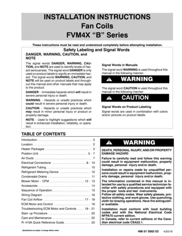
4Part 2 - Prepare the Fan CoilRemove all sides of the shipping crate to allow the fan coil to be movedinto its installation location.UNCRATING THE FAN COIL - Any claims for damage or shortagein shipment must be filed immediately against the transportationcompany by the consignee.B. Locating the Fan CoilThis fan coil is certified for indoor use only. DO NOT INSTALLOUTDOORS. Outdoor installations ARE NOT covered by warranty.Choose a location for the fan coil as centralized to the piping systemas possible. Also, locate the fan coil and piping where it will not beexposed to freezing temperatures. All piping should be insulated.Additionally, place the fan coil so that the drain, controls, and inlets/outlets are easily accessible.A. Included with the Fan CoilThe following items are included with the fan coil. Ensure all partsordered with the fan coil are received in good condition beforeproceeding with installation.This fan coil must be installed upright in the vertical position asdescribed in this manual. DO NOT attempt to install this fan coilin any other orientation. Doing so will result in improper fancoil operation and property damage, and could result in seriouspersonal injury or death.Ensure the installation location can support the entire filled weightof the fan coil. Failure to properly support the fan coil could resultin property damage, severe personal injury, or death.Regularly check that the installation location has not beendamaged by the weight of the fan coil and that the fan coil has notbegun to tip or lean and become unlevel. Failure to do so couldresult in property damage, severe personal injury, or death.COLD WEATHER HANDLING - If the fan coil has been stored ina very cold location (BELOW 0oF) before installation, handle withcare until the components come to room temperature. Failure todo so could result in damage to the fan coil.Locate the fan coil where any leakage will not result in damageto surrounding areas or lower floors of the building. The fan coilshould be located near a floor drain or installed in a drain pan.Leakage damages ARE NOT covered by warranty.NOTE: To save on heating costs and improve energy efficiency keepthe distance between the fan coil and heating or cooling source to aminimum to reduce temperature loss from excess piping and keepfriction loss at a minimum. Ensure all piping between the heating orcooling source and fan coil is properly insulated to minimize heatloss.The fan coil may be located some distance from the heating orcooling source provided the circulator meets flow requirements. Thegreater the distance from the source to the fan coil the longer theresponse will be to a call for heat or cooling.This fan coil must be installed vertical on a level surface.Thermostat Wire HarnessFigure 1 - Included Parts - NOTE: Not all components are requiredfor the installation. For example, if the fan coil is wall mounted,the feet are decorative and optional. *3-Way Valve included with“V” suffix fan coil models ONLY, but may be purchased as an optional part.See Replacement Parts, these instructions, for part number.lp-587 Rev. 000 Rel. 001 Date 2.12.18NOTE: In the State of California, the fan coil must be braced, anchored,or strapped to avoid moving during an earthquake. Contact localutilities for code requirements in your area. Visit http://www.dsa.dgs.ca.gov or call 1-916-445-8100 and request instructions.However, applicable local codes shall govern installation. Consultthe local building jurisdiction for acceptable bracing procedures.NOTE: If you do not provide the minimum clearances shown inFigure 1, it might not be possible to service the fan coil withoutremoving it from the space.This fan coil must not be located near flammable liquids such asgasoline, butane, liquefied propane, adhesives, solvents, paintthinners, etc., as the controls of this fan coil could ignite thesevapors and cause an explosion resulting in property damage,severe personal injury, or death.
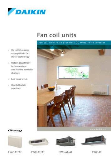
5D. Information and RecommendationsThe fan coil is equipped with: An integrated thermostat control. A “TT” or “remote on/off” which can be used to call for heatingor cooling. A water control bypass valve for use in a continuously circulating(or forced) water system. The fan coil can be used with orwithout the bypass valve depending on the installation. If thefan coil is used in a single unit installation, it is recommendedto remove the bypass valve.In addition: The manufacturer primarily recommends the fan coil for usein heating applications paired with an HTP heating appliance. This fan coil is capable of heating or cooling when installedwith other equipment not included with the fan coil (e.g. boilerfor heating, a chiller for cooling, or a reversible heat pump forheating and cooling). This fan coil is capable of switching a heat pump betweenheating and cooling. This fan coil can communicate with building managementsystems through an RS 485 connection.Consult with an experienced, certified HVAC professional to discussthe many options available for integrating this product into your HVACsystem.Figure 2 - Recommended Service ClearancesC. Water Chemistry RequirementsChemical imbalance of the water supply may affect efficiencyand cause severe damage to the fan coil and associatedequipment. The manufacturer recommends having water qualityprofessionally analyzed to determine whether it is necessary toinstall a water softener. It is important that the water chemistry bechecked before installing the fan coil, as water quality will affectthe reliability of the system. Failure of a fan coil due to lime scalebuild-up, low pH, or other chemical imbalance IS NOT covered bythe warranty. Sodium less than 20 mGLWater pH between 6.0 and 8.0 Maintain water pH between 6.0 and 8.0. Check withlitmus paper or have it chemically analyzed by watertreatment company. If the pH differs from above, consult local water treatmentfor treatment needed. Hardness less than 7 grains Consult local water treatment companies for unusuallyhard water areas (above 7 grains hardness). Chlorine concentration less than 100 ppm Using chlorinated fresh water should be acceptable aslevels are typically less than 5 ppm. Do not fill fan coil or operate with water containingchlorine in excess of 100 ppm.*NOTE: It is recommended to clean the heat exchanger at least oncea year to prevent lime scale buildup. To clean the heat exchanger,follow the maintenance procedure in this manual.Hardness: Less than 7 grainsChloride levels: Less than 100 ppmpH levels: 6 - 8TDS: Less than 2000 ppmSodium: Less than 20 mGLlp-587 Rev. 000 Rel. 001 Date 2.12.18
6Part 3 - Technical SpecificationsA. 96002460032000Water Flow Rate (1)Gallons / Min0.971.502.162.733.56Pressure Drop U/hr46008500114001460017800Water Flow Rate (2)Gallons / Min1.011.892.553.263.92Pressure Drop U/hr3400650085001200014800Water Flow Rate (3)Gallons / Min0.751.451.892.643.30Pressure Drop (3)psig1.611.934.024.104.44Air VolumeCFM94188270340381303237394124306980Heating Capacity (1)Heating Capacity (2)Cooling Capacity (3)Noise (4)dB (A)Power Supply/Power InputW110 - 220V /60 Hz121620Water In / OutNPT3/4”Draininch0.63Shipping Weight (est.)lb455360Table 1 - Fan Coil Technical Specifications (5) - ** ”WV” Denotes White Models with Valve; “B” Denotes Black Models without ValveTest Conditions(1) Heating test conditions based on input water temperature of 158oF, difference in temperature of 50oF, and entering air temperature of68oF DB.(2) Heating test conditions based on input water temperature of 122oF, difference in temperature of 41oF, and entering air temperature of68oF DB.(3) Cooling test conditions based on input water temperature of 44.6oF, difference in temperature of 41oF, and entering air temperature of66.2 / 80.6oF DB.(4) Noise level is measured in the standard anechoic chamber 17dB(A).(5) Above data is subject to change without notification.Working ConditionsHeating: Ambient temperature of 41 - 84.2oF, Inlet Water temperature of 95 - 158oFCooling: Ambient temperature of 48.2 - 95oF, Inlet Water temperature of 41 - 68oFlp-587 Rev. 000 Rel. 001 Date 2.12.18
7B. DimensionsFigure 3 - Overall Product VFC-32G**Dimension A (Inches)27.3635.2443.1150.9958.86Table 2 - Fan Coil Dimensions - ** ”WV” Denotes White Models with Valve; “B” Denotes Black Models without ValveC. Description of OperationThe Ultra Thin Hydronic Fan Coil uses water to provide heated air inthe winter and cooled, dehumidified air in the summer. Incomingair is drawn up through the fan coil and either heated or cooled(depending on installation) over the water pipes before beingdirected out of the top.Compared with traditional fan coils, the Ultra Thin hydronic Fan Coil isthinner, quieter, and more aesthetically pleasing, and can be installedin various ways, such as floor installation, wall installation, ceilinginstallation and concealed installation, thus reducing installationcosts.Figure 4 - Description of Operationlp-587 Rev. 000 Rel. 001 Date 2.12.18
8Part 4 - InstallationA. PrecautionsCarefully follow these instructions to ensure correct fan coil installationand proper operation. Failure to follow these instructions can result inappliance malfunction and WILL VOID the warranty.It is important that the electrical installation be made according to theNational Electrical Code and local rules and regulations while followingthe data indicated in the technical specifications in this manual. Ensurethe fan coil is properly grounded.The fan coil must be installed in a position that allows for routinemaintenance, such as filter cleaning.B. Positioning the Fan CoilAvoid installing the unit in proximity to: Positions subject to exposure to direct sunlight; Heat sources; Damp areas or places with probable contact with water;Figure 6 - Mounting Template Places with oil fumes; Places subject to high frequencies.Ensure that: The wall on which the fan coil is installed is strong enough tosupport the weight; The wall does not have pipes or electrical wires passingthrough it; The wall is flat and level; There are no obstacles which could interfere with inlet andoutlet air flow; The wall is preferably on the outer perimeter to allow dischargeFigure 7 - Leveling the Bracketsof condensate outdoors.C. Mounting1. Lift the screw cap (Figure 5, ref A) that protects the screws.2. Remove the fixing screws with a screwdriver (Figure 5, B).3. Move the side panel slightly and lift it out (Figure 5, C).Figure 8 - Mounting the Bracket7. Mount the optional feet before installing the unit on the floor.a. First, lay the unit down.b. Next, remove the screws and two (2) feet from theaccessories bag.c. Position the feet so that the screw holes A / B / C / D matchFigure 5 - Removing the Side Panelup with the holes on the unit. See Figures 9 and 10.4. Use the included paper template to trace the mounting position ond. Use four (4) screws on each foot to properly install the feetthe wall. See Figure 6.to the fan coil. See Figure 10.5. Place the mounting brackets on the wall over the traced holes andcheck them with a level. See Figure 7.6. If level, use a suitable drill to make the mounting holes and insert thetoggle bolts (two [2] bolts each bracket). See Figure 8, A.7. Check the brackets again with a level. See Figure 7. If level, tightenthe two brackets. See Figure 8, B.Figure 9 - Mounting the Optional Feetlp-587 Rev. 000 Rel. 001 Date 2.12.18
9Figure 10 - Mounting Feet Locations8. Mount the fan coil onto the mounting brackets. Ensure that thefan coil is stable and level. See Figure 11.Figure 11 - Mounting the Fan Coil to the BracketD. Water PipingFigure 12 - Water Inlet and Outlet without ValvesRefer to Figures 12 through 17 for water piping applications. The water lines should be kept as short as possible.The piping system should be clean, with no sediment,corrosion, or jams in the pipeline. Sediment, corrosion, orjams could lead to water leakage. The water lines should be connected to the water tank andthe height of the water should be 19.69” higher. Y type filter should be installed in the water inlet of the unit. Air release valve should be installed above the water linesto prevent air retention. Piping system should be pressure tested seperately andnot with the fan coil.Failure to follow these instructions could result in propertydamage and WILL VOID product warranty.Figure 13 - Water Inlet and Outlet with Valveslp-587 Rev. 000 Rel. 001 Date 2.12.18
10Figure 14 - Flex Pipe Installation Downward to Inlet and Outlet withoutValves - Type 1Figure 16 - Flex Pipe Installation Downward to Inlet and Outlet withValves - Type 1 - OptionalFigure 15 - Flex Pipe Installation Backward to Inlet and Outlet withoutValves - Type 2E. Condensate PipingWhen installing the condensate discharge device in vertically mountedfan coils, connect the condensate collection tray discharge union(Figure 18, C) to a pipe (Figure 18, B), and pipe discharge to a drain. Thedischarge pipe must be adequately sized (minimum inside diameterof 0.63 inches).Figure 17 - Flex Pipe Installation Backward to Inlet and Outlet withValves - Type 2 - Optional When discharging directly into open drains it is advisableto make a siphon to prevent odors from the pipe enteringthe room. The curve of the siphon must be lower than thecondensate collection orifice. If the condensate is to be discharged into a container, thepipe must be open to the atmosphere and the terminal mustnot be submerged in water to avoid vacuum locks that wouldinterfere with normal outflow.Failure to follow these instructions could result in property damageand WILL VOID product warranty.Figure 18 - Condensate Detaillp-587 Rev. 000 Rel. 001 Date 2.12.18
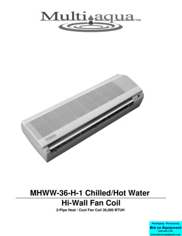
11F. PurgingBegin filling the system by opening the inlet and outlet valves. Use ascrewdriver to open the purge screw. See Figure 19, A. When waterstarts coming out, close the purge screw. Continue filling the systemuntil it reaches the nominal pressure value. Check the seals of thegaskets and ensure there are no leaks.It is advisable to repeat this procedure after the appliance has beenrunning for a few hours and periodically check the pressure of thesystem.NOTE: If the system is powered and a thermo-valve is installed, use aspecial cap to press the valve stopper and open the valve.Figure 19 - Air Purge DetailPart 5 - OperationA. Control DescriptionFigure 20 - Display and Control DetailPower ButtonPressing this button turns the fan coil on and off, cancels a selection, or returns to the main display screen.Air Vent / Time ButtonAllows the user to display the time, set the timer, or turn On / Off the air vent.Fan Speed ButtonSets the fan speed.Up ArrowPages up. Increases a value.Down ArrowPages down. Decreases a value.Mode ButtonChanges operating modes.Table 3 - Display and Control DescriptionsNOTE: The display will dim after one (1) minute of no operation, unless the fan coil is in a fault condition.lp-587 Rev. 000 Rel. 001 Date 2.12.18
12B. Using the Display1. On / OffFigure 21 - Turning the Fan Coil On / Off2. Switching Between ModesPress the Mode button to switch between operating modes. There are five operating modes: Auto, Cooling, Dehumidifying, Ventilation, andHeating.Figure 22 - Turning the Fan Coil On / Offlp-587 Rev. 000 Rel. 001 Date 2.12.18
133. Setting the TemperatureAt the main display, press eithertemperature setting.orto begin changing the target temperature. Then pressto increase orto decrease theFigure 23 - Setting the Temperature4. Fan Speed Settinga. Changing the Fan SpeedAt the main display, pressto switch fan speed from low, to medium, to high.Figure 24 - Changing the Fan Speedb. Switching the Fan Speed to Extra HighAt the main display, press and holdspeed.for five (5) seconds to switch the fan speed to extra high. Pressagain to return to normal fanFigure 25 - Changing the Fan Speed to Extra HighNOTE: In Auto and Dehumidifying Modes the fan speed will adjust automatically according to the ambient temperature.lp-587 Rev. 000 Rel. 001 Date 2.12.18
145. Using the Timer and Sleep ModeFigure 26 - Setting the Timer and Sleep Modelp-587 Rev. 000 Rel. 001 Date 2.12.18
156. Check the Unit StatusAt the main display, pressorat the same time to check the fan coil temperature.Figure 27 - Checking the Fan Coil TemperatureNOTE: Users can only view this parameter. It cannot be changed.7. Keyboard LockFigure 28 - Operating the Keyboard Lock8. Air VentFigure 29 - Operating the Air Vent9. Fault DisplayFigure 30 - Viewing Fault Codeslp-587 Rev. 000 Rel. 001 Date 2.12.18
16C. Remote Control (Optional) DescriptionFigure 31 - Remote Control DetailPower ButtonPressing this button turns the fan coil on and off.Mode ButtonPress this button to choose from the Automatic, Cooling, Dehumidifying, Ventilating, and Heating Modes.Fan Speed ButtonPress this key to choose from High, Medium, and Low Fan Speeds.Up ArrowIncrease the setting by pressing this button.Down ArrowDecrease the setting by pressing this button.Table 4 - Display and Control DescriptionsNOTE: Take out the batteries from the remote if it is not to be used for along time. If the remote is not working properly, take out the batteriesfor thirty-five (35) minutes to allow it to reset. Replace the batteries.The remote should work normally.D. Using the Remote Control1. F. Cool and F. Heat FunctionPress the “F. Cool” or “F. Heat” buttons to automatically set the fan coilto either Cooling or Heating Mode at high fan speed.2. Time SettingPress and hold thebutton until the time value flashes. Adjust the3. Timing Start-Up or Timing Shut-DownNOTE: Timing Start-Up is only available when the fan coil IS NOToperating. DO NOT shut power supply off to the fan coil whensetting Timing Start-Up. Timing Shut-Down is only available whenthe fan coil IS operating.Press the Timing Start-Upbutton while the fan coil is notoperating to set Timing Start-Up. Use theorbuttonsto set the number of hours the fan coil will operate. The unit willautomatically begin to operate one hour after setting Timing StartUp.current time value by pressingto increase orto decrease. To NOTE: The range of Timing Start-Up is from 1 to 11 hours. If thesetting is over 11 hours the Timing Start-Up setting will be cancelled.save the time setting, press thebutton again.NOTE: A 12 hour clock displays the current time value. A 24 hour clock Press the Timing Shut-Downbutton while the fan coil isis not available.lp-587 Rev. 000 Rel. 001 Date 2.12.18
17operating to set Timing Shut-Down. Use theorbuttonsto set the number of hours the fan coil will operate. The unit willautomatically stop operating one hour after setting Timing ShutDown.NOTE: The range of Timing Shut-Down is from 1 to 11 hours. Ifthe setting is over 11 hours the Timing Shut-Down setting will becancelled.4. Sleep FunctionNOTE: The Sleep Function can only be set while the fan coil is inHeating or Cooling Mode.a. To begin or cancel the Sleep Function, press thebutton.b. When the Sleep Function is activated, theicon will beshown on the top right corner of the remote control’s LCD screen.“TIME OFF” and “7” will be shown on the lower right corner of theLCD screen. This means that the fan coil will automatically shutdown seven (7) hours after setting the Sleep Function. To changethe amount of hours or cancel the time setting altogether, pressthekey.c. One (1) hour after setting the Sleep Function, the fan speedwill automatically reduce to low. However, while Sleep Functionis set, fan speed can be changed by pressing.d. Two (2) hours after setting the Sleep Function in Cooling Modethe temperature setting will increase 1oC or about 2oF per hour.e. Three (3) hours after setting the Sleep Function in HeatingMode the temperature setting will decrease 1oC or about 2oF perhour.5. Change Temperature MeasurementPressto switch Temperature Measurement from Celsius toFahrenheit.6. Illuminate the LED ScreenPress thekey to light or turn off the LED Screen on the fan coil.E. Default SettingsModeDefault SettingCooling Temperature78oFHeating Temperature68oFAutomatic Setting Temperature72oF13Is the fan coil used as the maintemperature controller?0 (No) - 1(Yes)014Address1 - 991515Lock the Control?16Use the
the distance between the fan coil and heating or cooling source to a minimum to reduce temperature loss from excess piping and keep friction loss at a minimum. Ensure all piping between the heating or cooling source and fan coil is properly insulated to minimize heat loss. The fan coil may be located some distance from the heating or