Transcription
One of aseries n SystemPerformanceNT OFMEENRTEREDMU N ITICAGYERDEPAa sourcebook for industrySTAAT E S OFU.S. Department of EnergyEnergy Efficiency and Renewable EnergyBringing you a prosperous future where energy is clean,abundant, reliable, and affordable
AcknowledgmentsImproving Fan System Performance: A Sourcebook for Industry has been developed by the U.S. Departmentof Energy’s (DOE) Industrial Technologies Program and the Air Movement and Control AssociationInternational, Inc. (AMCA), a DOE Allied Partner. Industrial Technologies and AMCA Internationalundertook this project as part of a series of sourcebook publications on motor-driven equipment under theBestPractices effort. Other topics in this series include compressed air systems, pumping systems, and motorsand drives. For more information about the Industrial Technologies’ BestPractices effort and AMCAInternational, see Section 3.AMCA International is a not-for-profit association of the world’s manufacturers of related air systemequipment—primarily, but not limited to fans, louvers, dampers, air curtains, airflow measurement stations,acoustic attenuators, and other air system components—for industrial, commercial, and residential markets.The association’s mission is to promote the health and growth of industries covered by its scope and themembers of the association consistent with the interests of the public.DOE, AMCA International, Lawrence Berkeley National Laboratory, and Resource Dynamics Corporation thankthe staff at the many organizations that so generously assisted in the collection of data for this sourcebook.The contributions of the following participants are appreciated for their review and input to this sourcebook:Gary Benson, The New York Blower CompanyFrank Breining, Airmaster Fan CompanyDon Casada, Diagnostic Solutions, LLCBrad Gustafson, U.S. Department of EnergyTom Gustafson, Hartzell Fan, Inc.Tony Quinn, American Fan Company & Woods USA DivisionPaul Saxon, Air Movement and Control Association International, Inc.Bill Smiley, The Trane CompanySastry Varanasi, ABB Fan Group North AmericaDick Williamson, Twin City Fan Companies, Ltd.Ron Wroblewski, Productive Energy SolutionsPrepared for:The United States Department of EnergyAir Movement and Control Association International, Inc.Prepared by:Lawrence Berkeley National LaboratoryWashington, DCResource Dynamics CorporationVienna, VACover photo credit: Copyright CML Northern Blower Inc., 1989. All rights reserved. This image may not be reproduced,stored, or transmitted in any form or means without the prior written consent of the copyright holder.
ContentsQuick Start Guide1Section 1: Introduction to Fan SystemsFans33Fan Performance Curves6Fan System Components9Section 2: Performance Improvement Opportunity Roadmap151—Assessing Fan System Needs172—Fan Types193—Basic Maintenance254—Common Fan Systems Problems295—Indications of Oversized Fans336—System Leaks377—Configurations to Improve Fan System Efficiency398—Controlling Fans with Variable Loads439—Fan Drive Options4710–Multiple-Fan Arrangements5111–Fan System Economics55Section 3: Programs, Contacts, and ResourcesIndustrial Technologies Program and BestPractices5959Air Movement and Control Association International, Inc. (AMCA International) 63Directory of Contacts65Resources and Tools67Appendices75Appendix A: Fan System Terminology75Appendix B: The Fan System Marketplace83A Sourcebook for Industryi
iiImproving Fan System Performance
Quick Start GuideQuick Start GuideThis sourcebook is designed to provide fan systemusers with a reference outlining opportunities toimprove system performance. It is not intended tobe a comprehensive technical text on improvingfan systems, but rather a document that makes usersaware of potential performance improvements,provides some practical guidelines, and details wherethe user can find more help. The sourcebook isdivided into three main sections and appendices. Section 1: Introduction to Fan SystemsFor users unfamiliar with the basics of fans and fansystems, a brief discussion of the terms, relationships,and important system design considerations isprovided. This section describes the key factorsinvolved in fan selection and system design andprovides an overview of different types of fans andthe applications for which they are generally used.Users already familiar with fan system operationmay want to skip this section. The key terms andparameters used in selecting fans, designingsystems, and controlling fluid flow are discussed. Section 2: Performance ImprovementOpportunity RoadmapThis section describes the key components of a fansystem and the opportunities for performance improvements. Also provided is a figurative system diagramidentifying fan system components and performanceimprovement opportunities. A set of fact sheetsdescribing these opportunities in greater detailfollows the diagram. These fact sheets cover:1. Assessing Fan System Needs2. Fan Types3. Basic Maintenance4. Common Fan Systems Problems5. Indications of Oversized Fans6. System Leaks7. Configurations to Improve Fan System Efficiency8. Controlling Fans with Variable Loads9. Fan Drive Options10. Multiple-Fan Arrangements11. Fan System EconomicsA Sourcebook for Industry Section 3: Programs, Resources, and ContactsSection 3 provides a directory of associations andother organizations involved in the fan marketplace,along with a listing of the resources, tools, software,videos, and workshops. AppendicesThe sourcebook includes two appendices. Appendix Ais a glossary that defines terms used in the fansystem industry. Appendix B presents an overviewof the fan system marketplace.The Systems ApproachThe cost-effective operation and maintenance of afan system requires attention not only to the needsof the individual pieces of equipment, but also tothe system as a whole. A “systems approach”analyzes both the supply and demand sides of thesystem and how they interact, essentially shiftingthe focus from individual components to totalsystem performance. Often, operators are so focusedon the immediate demands of the equipment thatthey overlook the broader question of how systemparameters are affecting the equipment. Thesystems approach usually involves the followingtypes of interrelated actions: Establishing current conditions and operatingparameters Determining present and estimating futureprocess production needs Gathering and analyzing operating data anddeveloping load duty cycles Assessing alternative system designs andimprovements Determining the most technically andeconomically sound options, taking intoconsideration all of the subsystems Implementing the best option Assessing energy consumption with respect toperformance Continuing to monitor and optimize the system Continuing to operate and maintain the systemfor peak performance.1
2Improving Fan System Performance
Introduction to Fan SystemsSection 1: Introduction to Fan SystemsFans1 are widely used in industrial and commercialapplications. From shop ventilation to materialhandling to boiler applications, fans are criticalfor process support and human health. In themanufacturing sector, fans use about 78.7 billionkilowatt-hours2 of energy each year. This consumption represents 15 percent of the electricityused by motors.3 Similarly, in the commercialsector, electricity needed to operate fan motorscomposes a large portion of the energy costs forspace conditioning.Performance may range from “free air” to severalpounds per square inch gage (psig)4, withairflow from a few cubic feet per minute (cfm)to more than 1 million cfm. Pressures above15 psig generally require air compressors, whichare addressed in a separate sourcebook titledImproving Compressed Air System Performance,A Sourcebook for Industry.In manufacturing, fan reliability is critical to plantoperation. For example, where fans serve materialhandling applications, fan failure will immediatelycreate a process stoppage. In industrial ventilationapplications, fan failure will often force a processto be shut down (although there is often enoughtime to bring the process to an orderly stoppage).Even in heating and cooling applications, fanoperation is essential to maintain a productive workenvironment. Fan failure leads to conditions inwhich worker productivity and product qualitydeclines. This is especially true for some productionapplications in which air cleanliness is critical tominimizing production defects (for example,plastics injection molding and electronic componentmanufacturing).In each case, fan operation has a significant impacton plant production. The importance of fan reliabilityoften causes system designers to design fansystems conservatively. Concerned about beingresponsible for under-performing systems, designerstend to compensate for uncertainties in the designprocess by adding capacity to fans. Unfortunately,oversizing fan systems creates problems that canincrease system operating costs while decreasingfan reliability.Fans that are oversized for their service requirementsdo not operate at their best efficiency points. Insevere cases, these fans may operate in an unstablemanner because of the point of operation on thefan airflow-pressure curve. Oversized fans generateexcess flow energy, resulting in high airflow noiseand increased stress on the fan and the system.Consequently, oversized fans not only cost more topurchase and to operate, they create avoidablesystem performance problems. The use of a“systems approach” in the fan selection processwill typically yield a quieter, more efficient, andmore reliable system.FansThere are two primary types of fans: centrifugaland axial. These types are characterized by thepath of the airflow through the fan. Centrifugalfans use a rotating impeller to increase the velocityof an airstream. As the air moves from the impellerhub to the blade tips, it gains kinetic energy. Thiskinetic energy is then converted to a static pressureincrease as the air slows before entering the discharge.Centrifugal fans are capable of generating relativelyhigh pressures. They are frequently used in “dirty”airstreams (high moisture and particulate content),in material handling applications, and in systemsat higher temperatures.1 For the purposes of this sourcebook, the term “fan” will be used for all air-moving machines other than compressors.2 United States Industrial Electric Motor Systems Market Opportunities Assessment, U. S. Department of Energy, December 1998.3 Ibid.4 At standard conditions, a column of water 27.68 inches high exerts 1 psig of pressure. Equivalently, 1 inch of water gage 0.036 psig.A Sourcebook for Industry3
Introduction to Fan SystemsAxial fans, as the name implies, move an airstreamalong the axis of the fan. The air is pressurized bythe aerodynamic lift generated by the fan blades,much like a propeller and an airplane wing.Although they can sometimes be used interchangeably with centrifugal fans, axial fans are commonlyused in “clean air,” low-pressure, high-volumeapplications. Axial fans have less rotating mass andare more compact than centrifugal fans of comparable capacity. Additionally, axial fans tend to havehigher rotational speeds and are somewhat noisierthan in-line centrifugal fans of the same capacity;however, this noise tends to be dominated by highfrequencies, which tend to be easier to attenuate. Fan SelectionFan selection is a complex process that starts witha basic knowledge of system operating requirementsand conditions such as airflow rates, temperatures,pressures, airstream properties, and system layout.The variability of these factors and other considerations, such as cost, efficiency, operating life,maintenance, speed, material type, space constraints, drive arrangements, temperature, andrange of operating conditions, complicate fanselection. However, knowledge of the importantfactors in the fan selection process can be helpfulfor the purposes of reducing energy consumptionduring system retrofits or expansions. Often, a fantype is chosen for nontechnical reasons, such asprice, delivery, availability, or designer or operatorfamiliarity with a fan model. If noise levels, energycosts, maintenance requirements, system reliability,or fan performance are worse than expected, thenthe issue of whether the appropriate fan type wasinitially selected should be revisited.Fans are usually selected from a range of modelsand sizes, rather than designed specifically fora particular application. Fan selection is basedon calculating the airflow and pressure requirements of a system, then finding a fan of the rightdesign and materials to meet these requirements.Unfortunately, there is a high level of uncertaintyassociated with predicting system airflow andpressure requirements. This uncertainty, combinedwith fouling effects and anticipated capacityexpansion, encourages the tendency to increasethe specified size of a fan/motor assembly.4Designers tend to protect against being responsiblefor inadequate system performance by “overspecifying.” However, an oversized fan/motorassembly creates a different set of operatingproblems, including inefficient fan operation,excess airflow noise, poor reliability, and pipe/ductvibrations. By describing some of the problemsand costs associated with poor fan selection, thissourcebook is intended to help designers and operators improve fan system performance through better fan selection and improved operating andmaintenance practices.Noise. In industrial ventilation applications, noisecan be a significant concern. High acoustic levelspromote worker fatigue. The noise generated by afan depends on fan type, airflow rate, and pressure.Inefficient fan operation is often indicated by acomparatively high noise level for a particular fantype.If high fan noise levels are unavoidable, thenways to attenuate the acoustic energy should beconsidered. Noise reduction can be accomplishedby several methods: insulating the duct; mountingthe fan on a soft material, such as rubber or suitable spring isolator as required to limit the amountof transmitted vibration energy; or installing sounddamping material or baffles to absorb noise energy.Rotational Speed. Fan rotational speed is typicallymeasured in revolutions per minute (rpm). Fanrotational speed has a significant impact on fanperformance, as shown by the following fan laws:Airflowfinal Airflowinitial( RPMRPMPressurefinal PressureinitialPowerfinal Powerinitialfinalinitial)RPMfinal2( RPM )initialRPMfinal 3( RPM )initialImproving Fan System Performance
Introduction to Fan SystemsRotational speed must be considered concurrentlywith other issues, such as variation in the fan load,airstream temperature, ambient noise, andmechanical strength of the fan.Variations and uncertainties in system requirementsare critical to fan type and fan rotational speedselection. Fans that generate high airflow atrelatively low speeds (for example, forward-curvedblade centrifugal fans) require a relatively accurateestimate of the system airflow and pressure demand.If, for some reason, system requirements areuncertain, then an improper guess at fan rotationalspeed can cause under-performance or excessiveairflow and pressure.Airstream temperature has an important impact onfan-speed limits because of the effect of heat onthe mechanical strength of most materials. At hightemperatures, all materials exhibit lower yieldstrengths. Because the forces on shafts, blades, andbearings are proportional to the square of therotational speed, high-temperature applications areoften served by fans that operate at relatively lowspeeds.Airstream Characteristics. Moisture and particulatecontent are important considerations in selectingfan type. Contaminant build-up on fan blades cancause severe performance degradation and fanimbalance. Build-up problems are promoted by ashallow blade angle with surfaces that allow contaminants to collect. Fans with blade shapes thatpromote low-velocity air across the blades, such asbackward inclined fans, are susceptible tocontaminant build-up. In contrast, radial tip fansand radial blade fans operate so that airflow acrossthe blade surfaces minimizes contaminant build-up.These fans are used in “dirty” airstreams and inmaterial handling applications.Corrosive airstreams present a different set ofproblems. The fan material, as well as the fan type,must be selected to withstand corrosive attack.Also, leakage into ambient spaces may be aconcern, requiring the fan to be equipped with ashaft seal. Shaft seals prevent or limit leakage fromaround the region where the drive shaft penetratesthe fan housing. For example, in corrosive environments fans can be constructed with expensive alloysthat are strong and corrosion resistant, or they canA Sourcebook for Industrybe less expensively constructed with fiberglassreinforced plastic or coated with a corrosionresistant material. Because coatings are often lessexpensive than superalloy metals, fan types thatwork well with coatings (for example, radial fanblades because of their simple shape) are widelyused in corrosive applications; however, wear willreduce the reliability of coatings. Alternately, materials such as reinforced fiberglass plastics havebeen developed for fan applications and functioneffectively in many corrosive environments.However, there may be size and speed limitationsfor composite materials and plastic materials.Airstreams with high particulate content levels canalso be problematic for the fan drive train. In directdrive axial fans, the motor is exposed to theairstream. Sealed motors can be used in theseapplications but tend to be more expensive and,in the event of lost seal integrity, they are susceptible to expensive damage. In axial fans, belt drivesoffer an advantage by removing the motor from theairstream. In centrifugal fans, the particulatecontent is less of a factor because the motor orsheave can be located outside of the fan enclosureand connected to the impeller through a shaft seal.Gear drives are occasionally used in applicationswhere speed reduction is required but the useof belt drives is unfeasible because of access ormaintenance requirements.In flammable environments, fans are usuallyconstructed of nonferrous alloys to minimize therisk of sparks caused by metal-to-metal contact. Insome applications, certain components of the fancan be fabricated out of spark-resistant materials.Fans that operate in flammable environmentsshould be properly grounded, including rotatingcomponents, to minimize sparking because of static discharge.Temperature Range. To a large degree, temperaturerange determines fan type and material selection.In high-temperature environments, many materialslose mechanical strength. The stresses on rotatingcomponents increase as the fan’s operating speedincreases. Consequently, for high-temperatureapplications, the fan type that requires the lowestoperating speed for a particular service is oftenrecommended. Radial blade fans can be ruggedlyconstructed and are frequently used in5
Introduction to Fan Systemshigh-temperature environments. Component materialsalso significantly influence a fan’s ability to servein high-temperature applications, and differentalloys can be selected to provide the necessarymechanical properties at elevated temperatures.Variations in Operating Conditions. Applications thathave widely fluctuating operating requirementsshould not be served by fans that have unstableoperating regions near any of the expectedoperating conditions. Because axial, backwardinclined airfoil, and forward-curved fans tend tohave unstable regions, these fans are not recommended for this type of service unless there is ameans of avoiding operation in the unstableregion, such as a recirculation line, a bleed feature, or some type of anti-stall device.Space Constraints. Space and structural constraintscan have a significant impact on fan selection. Inaddition to dimensional constraints on the spaceavailable for the fan itself, issues such as maintenance access, foundation and structural supportrequirements, and ductwork must be considered.Maintenance access addresses the need to inspect,repair, or replace fan components. Because downtime is often costly, quick access to a fan can provide future cost savings. Foundation and structuralrequirements depend on the size and weight of afan. Selecting a compact fan can free up valuablefloorspace. Fan weight, speed, and size usuallydetermine the foundation requirements, which, inturn, affect installation cost.6small ducts, and very compact fan assemblies.Although this design practice may free up floorspace, the effect on fan system performance can besevere in terms of maintenance costs. The use ofmultiple elbows close to a fan inlet or outlet cancreate a costly system effect, and the addedpressure drops caused by small duct size or acramped duct configuration can significantlyincrease fan operating costs. System designersshould include fan system operating costs as aconsideration in configuring fan assemblies andductwork.Fan Performance CurvesFan performance is typically defined by a plot ofdeveloped pressure and power required over arange of fan-generated airflow. Understanding thisrelationship is essential to designing, sourcing, andoperating a fan system and is the key to optimumfan selection.Best Efficiency Point. Fan efficiency is the ratio ofthe power imparted to the airstream to the powerdelivered by the motor. The power of the airflow isthe product of the pressure and the flow, correctedfor units consistency. The equation for totalefficiency is:Total Efficiency Total Pressure x Airflowbhp x 6,362Where: Total Pressure is in inches of waterAirflow is in cubic feet per minute (cfm)bhp is brake horsepowerIf the available space requires a fan to be locatedin a difficult configuration (for example, with anelbow just upstream or downstream of a fan), thensome version of a flow straightener should beconsidered to improve the operating efficiency.Because non-uniform airflow can increase the pressure drop across a duct fitting and will degrade fanperformance, straightening the airflow will loweroperating costs. For more information, see the factsheet titled Configurations to Improve Fan SystemEfficiency on page 39.An important aspect of a fan performance curveis the best efficiency point (BEP), where a fanoperates most cost-effectively in terms of bothenergy efficiency and maintenance considerations.Operating a fan near its BEP improves itsperformance and reduces wear, allowing longerintervals between repairs. Moving a fan’s operatingpoint away from its BEP increases bearing loadsand noise.An important tradeoff regarding space and fansystems is that the cost of floor space oftenmotivates designers and architects to configure afan system within a tight space envelope. One wayto accomplish this is to use small-radius elbows,Another term for efficiency that is often used withfans is static efficiency, which uses static pressureinstead of total pressure in the above equation.When evaluating fan performance, it is importantto know which efficiency term is being used.Improving Fan System Performance
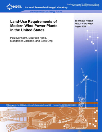
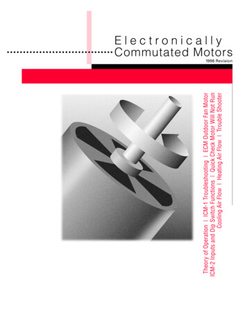
Introduction to Fan SystemsRegion of Instability. In general, fan curves arcdownward from the zero flow condition—that is,as the backpressure on the fan decreases, the airflow increases. Most fans have an operating regionin which their fan performance curve slopes in thesame direction as the system resistance curve.A fan operating in this region can have unstableoperation. (See Figure 1-1.) Instability results fromthe fan’s interaction with the system; the fan attemptsto generate more airflow, which causes the systempressure to increase, reducing the generated airflow. As airflow decreases, the system pressurealso decreases, and the fan responds by generatingmore airflow. This cyclic behavior results in asearching action that creates a sound similar tobreathing. This operating instability promotes poorfan efficiency and increases wear on the fancomponents.26Fan start-up is also the acceleration of a fan fromrest to normal operating speed. Many fans,particularly centrifugal types, have a large rotational inertia (often referred to as WR2), meaning theyrequire significant torque to reach operating speed.In this region, the slopes of the fan curveand the system curve are near parallel.Instability results when the fan curveintersects the system curve at more than onepoint, causing the fan to hunt.24Region of Instability22Fan Start-Up. Start-up refers to two different issuesin the fan industry. Initial fan start-up is thecommissioning of the fan, the process of ensuringproper installation. This event is important forseveral reasons. Poor fan installation can causeearly failure, which can be costly both in terms ofthe fan itself and in production losses. Like otherrotating machinery, proper fan operation usuallyrequires correct drive alignment, adequatefoundation characteristics, and true fit-up toconnecting ductwork.20Static Pressure(in. wg)1816FanCurve14SystemCurves12Slope 7,000Airflow Rate (cfm)Figure 1-1. Region of Instability55 Although fan system curves can have a static component, for the purposes of this sourcebook, system curves passthrough (0,0).A Sourcebook for Industry7
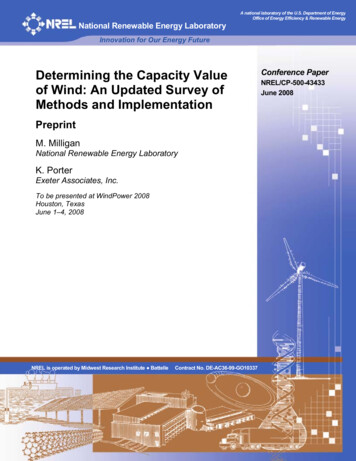
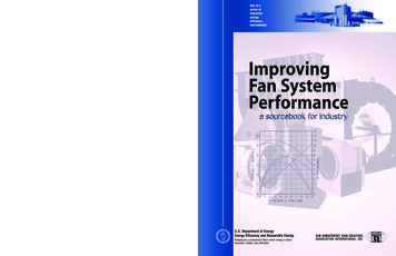
Introduction to Fan SystemsIn addition to the WR2 load, the air mass movedby the fan also adds to the start-up torque requirements on the fan motor. Although rotational inertiais not typically a problem in heating, ventilation,and air conditioning (HVAC) applications, it maybe a design consideration in large industrial applications. Proper motor selection is essentialin ensuring that the fan can be brought to itsoperating speed and that, once there, the motoroperates efficiently.Because the start-up current for most motors is 2to 5 times the running current, the stress on themotor can be significantly reduced by starting afan under its minimum mechanical load andallowing the motor to achieve normal operatingspeed more quickly than when under full load.In many applications, system dampers can bepositioned to reduce the load on the fan motorduring start-up. For example, the power requiredby a centrifugal fan tends to increase with increasingflow (although in “non-overloading” fan types, thepower drops off after reaching a peak). In axialfans, the power tends to decrease with increasingflow. Consequently, for most centrifugal fan types,large fan start-ups should be performed withdownstream dampers closed, while for most axialfan types, start-ups should be performed with thesedampers open. However, there are exceptions tothese guidelines, and the actual power curve forthe fan should be evaluated to determine how tosoften the impact of a large fan start-up.The power surges that accompany the starting oflarge motors can create problems. Among theeffects of a large start-up current are power qualityproblems and increased wear on the electrical system. In response to increasing demand for equipment that minimizes the problems associated withlarge motor starts, electrical equipment manufacturers are offering many different technologies,including special devices known as soft starters, toallow gradual motor speed acceleration. A keyadvantage of variable frequency drives (VFDs) isthat they are often equipped with soft starting features that decrease motor starting current to about1.5 to 2 times the operating current. Although VFDsare primarily used to reduce operating costs, theycan significantly reduce the impact of fan starts onan electrical system.8In axial fan applications, controllable pitch fansoffer a similar advantage with respect to reducingstart-up current. Shifting the blades to a low angleof attack reduces the required start-up torque ofthe fan, which allows the motor to reach operatingspeed more quickly. For more information onVFDs and controllable pitch fans, see the factsheet titled Controlling Fans with Variable Loadson page 43.System Effect. The system effect is the change insystem performance that results from the interactionof system components. Typically, during the designprocess, the system curve is calculated by addingthe losses of each system component (dampers,ducts, baffles, filters, tees, wyes, elbows, grills,louvers, etc.). The governing equation for pressureloss across any particular component is: p CWhere:2V( 1,097)ρ p pressure loss in inches of water gage(in. wg)C loss coefficient for the componentV velocity in feet per minuteρ density of the airstream (0.075 poundsper cubic foot at standard conditions)The result of this equation is a parabolic line, asshown by the system curve in Figure 1-2. Thissystem curve assumes all components displaypressure loss characteristics according to their losscoefficients. However, in reality, non-uniformairflow profiles that are created as the airstreamdevelops swirls and vortices cause systemcomponents to exhibit losses that are higher thantheir loss coefficients. The overall effect of theseadded losses is to move the system curve up, asshown by the corrected system curve in Figure 1-2.The system effect can be minimized by configuringthe system so that the flow profile remains asuniform as possible. However, if space constraintsprevent an ideal system layout, then system effectconsequences should be incorporated into the fanselection process. For more information on how tominimize losses, see the fact sheet titled Configurationsto Improve Fan System Efficiency on page 39.Improving Fan System Performance
Introduction to Fan Systems26System Curve (with system effect)242220Fan CurveStatic Pressure(in. wg)18System Curve(as calculated)16141210864Expected Performance2Actual 7,000
Quick Start Guide Section 1: Introduction to Fan Systems Fans 3 Fan Performance Curves 6 Fan System Components 9 Section 2: Performance Improvement Opportunity Roadmap 1—Assessing Fan System Needs 17 2—Fan Types 19 3—Basic Maintenance 25 4—Common Fan Systems Problems 29 5—Indications of Oversized Fans 33 6—System Leaks 37