Transcription
1Coil Cleaning: UV Fundamental Sizing and Energy Savingsby Normand Brais P.Eng., M.A.Sc., Ph.D.Vice-President, SANUVOX TECHNOLOGIES Inc.Normand Brais holds a mechanical engineering degree, aMaster of Applied Sciences, and a PhD in Nuclear Engineeringfrom Polytechnique of Montreal. He was appointed Professor atthe Energy Engineering Institute after he graduated. He hasfounded several technological companies in various fields suchas atmospheric pollution of stationary combustion equipment,biomass combustion, water treatment, photonics, andair/surface UV disinfection. In 1995 he founded SanuvoxTechnologies, which is now a worldwide technological leader inUV disinfection of air and surfaces for hospitals and officebuildings.ABSTRACTNearly every HVAC engineer has had the experience of opening a unit to find the drain pan and coilcovered with a slimy residue of mold biofilm. Not only these conditions can be unhealthy andoccasionally deliver unpleasant smell for building occupants, but it also ruins the heat transfer capacityof the system and consequently increases the energy operating cost.Various coil-cleaning methods have been used to try to control this problem. Many of those techniquesinvolve the use of detergents or even solvents, which can pose safety issues - health and flammability, forexample – and high pressure washing that diminishes the life of the coil, because sometimes acids areinvolved. Often coil cleaning isn't done with regularity and even when it is done on schedule, the moldgrowth can return in a very short time, usually less than a month.The use of germicidal ultraviolet light (UV-C) technology in air-handling systems now allows for aproactive method of keeping the coil clean and operating in "as new" performance all the time. UV-Clights can be added to air handlers and other pieces of equipment through a relatively simple and lowcost retrofit kit. Energy based payback ranges from 2 years to as low as 6 month depending upon the costof electricity and the operating conditions.Interestingly, while UV-C light has been promoted for its positive impact on indoor air quality (IAQ), the"bottom line" impact - its contribution to system energy efficiency and lower maintenance costs - mightultimately be considered to be its greatest asset.What Causes the Mold Biofilm Build-Up?Five conditions will result in mold and fungus growth causing a biofilm that inhibits fin heattransfer:1. A source of mold spores. Sufficient mold spores are found in nearly every environmentand brought into the building through door openings and outdoor air supplies.N. Brais Ph.D.September 2015
22. Even when HEPA filtration is used, the filter replacement causes a momentary breach ofthe sterility barrier that allows airborne mold spores to contaminate and colonize thecoils.3. Organic material on which the mold can grow. Dust and particles of organic material arealso readily available in every system, even with the best filtration systems.4. The right temperature range. Temperatures from 50 F to more than 100 F provide theright incubation range.5. Moisture, which is in more than adequate supply on cooling coils and drain pans of all airconditioning units.Even when filtration is provided, a large part of the build-up on the cooling coil is the result ofbiological growth.Effects of Biofilm Growth on a Cooling CoilThe presence of a biofilm on the fins of a coil has two direct effect:1) Major Heat transfer loss to the fins due to the much lower thermal conductivity of theorganic biofilm covering the aluminum fins.2) Slight Pressure drop increase due to the restriction of the flow area and consequently areduction of the air flow delivery capacity.As we will see in the following example, a biofilm growth can have significant impact on coilperformance, putting it considerably off design specification.If we consider the case of a cooling coil of 8 ft high by 9 ft wide that has consequently 72 sq ft.of face area and 29,150 cfm our gross face velocity is about 400 ft per minute. But this is not theactual velocity inside the coil between the fins. The fin and tube material do block a significantportion of the face coil area.Let's consider a typical coil of 12 fins per inch of 0.0055 inch thickness with copper tubes of 1/2”on a vertical Row Tube Spacing of 1.5 inch and horizontal Face Tube Spacing of 1.3 inch. As theair flowing at 400 ft/min enters the fins, it has to accelerate up to 428 ft/min to maintain the ratedue the blockage of the free cross section area. If we also consider that there are 72 face rows oftubes, the available free area is further squeezed down and the resultant inner coil velocity goesup to 740 ft/min.How does a bio-film build-up affect the performance? If the bio-film thickness is 1.5 thousandthof an inch (i.e. half the thickness of a common paper sheet) on the fin and tube surfaces, this willN. Brais Ph.D.September 2015
3reduce the free area down some more and increase the velocity up to 793 ft/min. What will anincrease of 53 ft/min (793-740) mean to pressure drop? Well, surprisingly, not much. Calculationshows that the pressure drop of his fouled coil will increase by only 0.09” of water column whichis hardly noticeable and quite difficult to measure. This means that when a high pressure dropdue to fouling is observed, that coil is then extremely fouled.If we now consider the effects of biofilm fouling on the heat transfer coefficient, we will see thatthis is where the performance loss is severe.A cooling coil is a liquid to air heat exchanger and as such its heat duty Q is the product of a heattransfer coefficient U, a heat transfer surface A, and the temperature difference between the hotair and the cooling fluid often called “delta T”and written . Hence the well-known basic heattransfer formula: When a tiny biofilm builds up on a coil, it adds an insulating layer on the heat transfer surfaces.This additional layer reduces the heat transfer coefficient U. Because the physical heat transfersurface cannot be changed, in order to maintain the heat exchange duty Q, only the temperaturedifferential can be increased to compensate. The only way to do this consists in decreasingthe cooling fluid temperature and consequently make the whole HVAC system (compressors,chillers, auxiliary equipment, etc.) work harder to produce a cooler fluid. Otherwise, the coolingheat duty of the coil is lost in the same proportion as the heat transfer coefficient reduction.Now let’s look at how much drop in heat duty a 0.0015 inch biofilm can cause. Such as biofilmis hardly visible as it is about half of a paper sheet.The flow in the small gap between fins has a low enough Reynolds number to be laminar and assuch a constant Nusselt number can be used to calculate the convective heat transfer coefficient.The overall heat transfer coefficient U is calculated by adding the thermal resistance of thebiofilm to the air boundary layer convective resistance. Where h convective heat transfer coefficient of the air stream on the clean finsk thermal conductivity of the biofilm materialt biofilm thicknessUsing well-known heat transfer data from available literature, the clean U value of the coildescribed above is found to be 7.32 BTU/hr/ft2/oF. The presence of our 0.0015 inch biofilm thathas a thermal conductivity of 0.003 BTU/hr/ft/ oF brings this number down to 5.78 BTU/hr/ft2/oF,hence a huge loss of 21% of the heat transfer coefficient U !N. Brais Ph.D.September 2015
4To maintain the heat duty performance of the coil, the temperature differential must be increasedby the same ratio. This will be done by lowering the cooling fluid temperature which willnegatively impact the coefficient of performance (COP) of the chiller. In order to be conservativein estimating the consequential reduction of the COP value, we will consider that the systemtrend is proportional to the best possible case i.e. the ideal Carnot cycle, which can be written asfollows:Where: Th Temperature of the Hot environment where heat is rejectedTc Temperature of the chiller Cooling fluidHence the new COP will be calculated according to the following relation: Based on the above, the COP will decrease from 3.0 down to 2.75. This drop in COP will causethe energy consumption of the cooling system to increase by 8.9 % to compensate for the foulingof the coil.Based on the above described fundamental physical principles of heat transfer and fluid flowapplied to HVAC coils, Sanuvox Technologies has programmed an engineering calculationmethodology to estimate the energy savings by keeping coils free of biofilms and theconsequential return on investment.INPUT PARAMETERS OF THE CALCULATION PROGRAMHere is an overview of all the parameters involved in the calculation and a brief description oftheir importance and impact on the final result.N. Brais Ph.D.September 2015
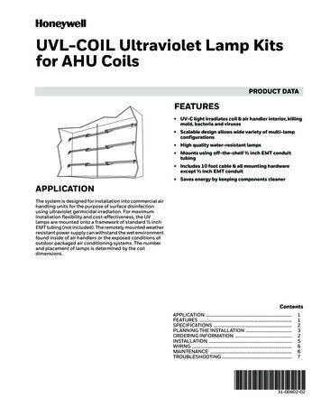
5PLEASE, FILL IN THE BASICS INFORMATIONSWHAT IS THE:Cooling Coil Height ?Cooling Coil Width?Cooling Coil Thickness?Air temperature entering the coil?Relative Humidity of air entering the coilAir temperature leaving the coil?Chilled water inlet temperature?Cost of electricity?% operating time?% operating load?Length of lamps required?Number of lamps required?Cost of replacement per lamp?Estimated UV system cost with install?Actual annual coil cleaning cost?UNITS9910612807550400,100 25804041002500500inchesinchesinchesdeg. F%deg. Fdeg. F/kWh%%inches if you dovalue of the leOPTIONAL: OTHER INFORMATIONS if neededWHAT IS THE:Default valueNumber of fins per inch?12Fin thickness?0,006Cooling tube outside diameter?0,500Row Tube Spacing ( Horizontal pitch)1,500Face Tube Spacing (Vertical Pitch)1,299Chiller COP?3,0Coil face air inlet velocity?400Biofilm thickness?0,0015Biofilm thermal resistance?0,003Interfin Moody friction factor?0,18Air thermal conductivity?0,0211inchinchinchinchEntering anotrecommended fft/mininBTU/hr.ft.RBTU/hr.ft.RN. Brais Ph.D.September 2015
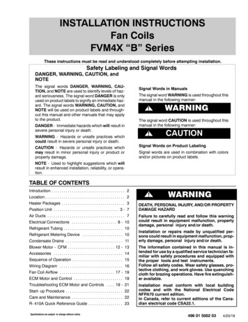
6OUTPUT OF THE CALCULATION PROGRAMCALCULATED VALUESValue /unitsAverage air densityCoil face areaNumber of Tube Face RowsNumber of Tube RowsCoil effective areaAir flowAir velocity between finsAir velocity between fins /tube crossingSpacing between finsSpacing between fins with biofilmAir velocity between fins with biofilmAir velocity between fins with biofilmEntering Air Humidity saturation pressureEntering Air dew point temperatureExiting air saturation pressureTotal air mass flow rateWater content in air entering the coilWater content of the air exiting the coilTotal water condensedAnnual coil cleaning costUV system installed costUV system electrical operating costUV system lamp maintenance costReturn on investment0,076 lb/ft373 ft276821 454 ft229 150 ACFM428 ft/min740 ft/min0,078 in0,0748 in445 ft/min793 ft/min0,513 psia71,4 deg.F0,178 psia132 691 lb/hr2 187 lb/hr1 010 lb/hr1 177 lb/hr500 2 500 350,40 year200,00 year12,5 monthsValue /unitsPressure drop accross clean coilPressure drop accross fouled coilPressure drop increase to biofilm foulingIncrease fan power due to coil foulingClean coil heat transfer coefficientFouled coil heat transfer coefficientHeat tranfer reduction due/biofilm foulingSensible heat absorbed by the coilLatent heat absorbed by the coilTotal heat duty of the coil0,595 in.wc0,685 in.wc0,090 in.wc0,526 kW7,32 BTU/hr.ft2.R5,78 BTU/hr.ft2.R21,0%955 2871 141 9842 097 271BTU/hrBTU/hrBTU/hrNormal operating LMTD of clean coilOperating LMTD of dirty coilDecrease cold water temp/maintain capacityChiller normal COPChiller operating COP at fouled LMTDEnergy loss due to the reduced COPClean Cooling coil operating costExtra cooling cost due to bio-fouling13,4 deg.F16,9 deg.F3,6 deg.F3,002,758,9%22 429 per year24 424 per yearDifference1 995 per yearFan operating cost due to fouling461 per yearTOTAL extra operating cost due to bio-fouling2 457 per yearPAYBACKApplying the heat duty based calculation program on the cooling coil described above provides apayback of a year. The payback will be faster for systems with: larger heat transfer surface (width, height, thickness, # fins per inch) higher electricity cost higher % operating load higher % operating time higher relative humidity / dehumidifying process lower cooling system COP valueN. Brais Ph.D.September 2015
7COMMENTS ABOUT THE INPUT PARAMETERS :1) Coil height, width and thickness are essential values along with the number of fins perinch to calculate the heat transfer surface A of the coil. An error on any of these 3parameters will significantly and proportionally affect the final operating cost. Great caremust be taken for these values.2) Air temperatures in and out as well as cooling fluid temperatures in and out are used inthe calculation of the temperature differential ΔT and since they are the second multiplierin the heat duty equation, they will affect directly the final operating cost. Also veryimportant to have reasonably accurate values.3) Cost of electricity is very important, needless to say. The higher it is the better the returnon investment by keeping the coil performance to its optimum.4) % Operating Time: the real cooling requirements (not free cooling) typically occursduring the hottest season. A season theoretically lasts 25% of the year, but the realcooling season can be as small as 15% of the year ( i.e. about 50 days) in northernclimates such as Canada and be as high as 80% of the year as we get near the equator. Wesuggest to pick 25% as a default guess value. Here again, it will directly affect the finaloperating cost and should be revised accordingly if the cost seems too high or too low.Here’s a suggested list of values based on reported monthly Cooling Degree-Days1(CCD) from the literature:Canada and North USA:Mid USA:Southern USA:Australia:Middle-East15%25%50%50%65%5) %Operating Load: given that HVAC engineers design the systems based on averagelocal climate conditions, there is a significant safety margin taken in the design.Therefore, in extremely rare hot conditions, the operating load can occasionally reach90% of installed capacity, but in general, the average operating load throughout thecooling season is expected to be somewhere around 60% or – 10%. Here again, it willdirectly affect the final operating cost and should be revised accordingly if the cost seemstoo high or too low.Definition of 'Cooling Degree Day - CDD'The number of degrees that a day's average temperature is above 65 o Fahrenheit and people start to use airconditioning to cool their buildings. To calculate the CDD, take the average temperature of a day and subtract 65.For example, if the day's average temperature is 80oF, its CDD is 15. If every day in a 30 day month had an averagetemperature of 80oF, the month's CDD value would be 450 (15 x 30).1N. Brais Ph.D.September 2015
86) COP : Coefficient of Performance of the chiller unit that supplies the cold fluid for thecoil. This value is the ratio of the amount of free energy that a heat pump can grab in theambient outside air to the energy consumption required to drive the cycle. It variesconsiderably from as low as 2 for single stage heat pumps used in lightcommercial/residential units up to 5 for large industrial ultra-efficient cooling cycles. Aconservative default value of 3 is used in the calculation. Its value will significantly affectthe final operating cost.7) Biofilm thickness is a default value that should not be played with too much. It has beenset conservatively at a default value of 0.0015 inch which is less than half a standardpaper sheet. Its value can have evidently a huge effect on performance and final results.8) All the other parameters do not have as much impact on the final results and unless thereare very clear and specific information provided by the clients, they shall remainuntouched.HOW MUCH UV IS REQUIRED TO ELIMINATE BIOFILM ANDRESTORE COIL EFFICIENCY ?UV coil cleaning can bring performance back to the original operating conditions.Typical coil cleaning methods include chemical treatments and/or steam cleaning. However,recent evidence suggests that both methods can be ineffective. Chemical cleaning may onlyremove surface growth while leaving material still embedded in the center of the fin pack. Somereports indicate that high pressure steam cleaning can actually force the surface growth deeper inthe fin pack compressing the growth material so tightly that the only solution may be a new coil.Both methods can also be detrimental to most of today's heat transfer enhanced fins surfaces.Coil cleaning is certainly necessary, but cannot be done economically with the frequency andlevel that will keep the coil operating at design conditions on a daily basis. In essence, with UVC lights, coil cleaning becomes a continuous, automatic and labor-free alternative. The UV-Clight works by attacking the DNA of the mold and rendering it sterile so that it cannot reproduce.Comparing physical cleaning methods to the use UV-C light is analogous to the differencebetween treating the symptoms rather than curing the disease.UV-C technology is not new, as it has proven itself for years as a way to provide sterilization inmedical and food processing applications. Given a properly engineered sizing methodology, UVN. Brais Ph.D.September 2015
9C lights can clean up a coil already contaminated by mold growth and keep the coil cleaner farbetter than any other methods.The effectiveness of the UV-C light is a function of the light intensity and exposure time.Aluminum coil fins are a good reflective surface and, as a result, the UV-C energy is capable ofpenetrating several row coils with excellent results.FUNDAMENTALS OF UV SIZING FOR HVAC COILSIn order to make sense of the sizing rules applicable to UV coil cleaning, it is essential to have agood understanding of the UV disinfection process. It is helpful to consider UV as the analogue ofa bombardment of photon bullets on a microbe. Each photon carries an amount of energy called aquantum Eλ , of a value connected to the light wavelength according to the Planck-Einsteinrelation:Where /Eq (1)h Planck’s constant, 6.626 x 10⁻³⁴ Joule.secc Speed of light in vacuum, 2.998 x 10⁸ m/secλ wavelength in m ( usually expressed in nanometers)Using the above Planck-Einstein relation, the energy conveyed by each UV-C photon at awavelength of 253.7 nm is equal to 7.83 x 10 -19 Joule. Therefore the number of photons per Jouleis the inverse i.e. 1.28 x 10¹⁸ photons per Joule.Keeping in mind that one watt of power is defined as one joule of energy per second, then a UVintensity of 100 Watt/m2 provides a flow of 1.28 x 10²⁰ photons per second per square meter.Considering that a virus of 0.2 micron diameter has a cross-sectional area of 3.14 x 10⁻¹⁴m2, despiteN. Brais Ph.D.September 2015
10its tiny size, this virus will be bombarded by 4 million photons per second. Given a sufficientduration time to this UV photons assault, photochemical damages will accumulate enough torender the organism biologically dysfunctional. In reality, regardless of the tremendous numberof photons shooting at this virus, only a very small number hit their target successfully to initiatethe photochemical reactions. The real effective inactivation cross sectional area of a target microbeis a function of many parameters, among them, the quantum chemical yield, the outside capsidprotective layers, and the particular distribution of its DNA sequence.Based on the above described UV bombardment analogy, a mathematical relation can be writtento express the UV dose response for a population of bio-organisms. It is reasonable to infer thatthe rate of decay of a microbial population will vary proportionally to the number of successfulhits over a period of time. This rate of successful hits can be described as the product of the UVpower per unit area I, the number of bio-organism N, the bio-organism effective UV inactivationcross section k, also called the bio-organism UV susceptibility constant, and the exposure time tas follow:Hit rate Integration of equation (2) yields:Where It Eq (2)Eq (3)N0 initial number of microorganisms,Nt number of microorganisms surviving after any time t,k a microorganism-dependent UV susceptibility constant, in m 2/Joule,I the irradiance UV intensity received by the microorganism, in Watt/m 2t exposure time, in secondsN. Brais Ph.D.September 2015
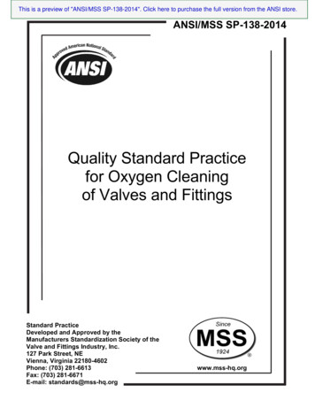
11The fraction of the number of microorganisms initially present, which survive at any given time,is called the survival ratio S and can be expressed as: Eq(4)The sterilized fraction is what is called the disinfection rate, is simply 1 minus the survival ratio. Eq(5)As explained above, we can define the germicidal UV dose by the total number of UV photonsemitted per unit area during a time interval, which can be written as: in Joule/m2Eq (6)By substituting equation (6) in equation (5), we finally get the well verified germicidal UV DoseResponse relation:Eq (7)Equation 7 illustrates that a given dose results in a given disinfection rate, whether the UV doseconsists of low UV intensity for a long exposure time, or a high UV intensity for a shorter time. Akey difference between surface decontamination and airborne inactivation of organisms isexposure time. The residence time for any in-duct disinfection will be of the order of a few secondsor a fractions of a second depending on airflow velocities. Therefore, the UV intensities forneutralization of an airborne microorganism are required to be orders of magnitude higher thanthat typically used for stationary surface disinfection such as walls or air-conditioning coolingcoils.Equations 3, 5, and 7 shown in figure 1 describes an exponential decay in time of the number ofliving organisms as a constant level of UVGI exposure intensity is applied. The very same type ofN. Brais Ph.D.September 2015
12equation is used to describe the effect of chemical disinfectants on a population of microorganisms,with the dose in this example being a chemical concentration multiplied by the contact time.Fig.1 Disinfection rate –vs- UV exposure time for various UV susceptibilitySusceptibility of microorganisms to UV energyOrganisms differ in their susceptibility to UV inactivation. A few examples of familiar pathogenicorganisms are included in each group for reference. It is important to note that it is impossible tolist all the organisms of interest in each group. Depending upon the application a public health ormedical professional, microbiologist or other individual with knowledge of the microbial threat ororganisms of concern should be consulted.N. Brais Ph.D.September 2015
13Based upon equation 5, it is clear that larger values of k represent more susceptible microorganismsand smaller values represent less susceptible ones. Units of k are m 2/Joule which is the inverse ofthe units used in UV dose. For example, the value of the UV susceptibility of Influenza-A virushas been measured experimentally by Jensen in 1964 and was found to be 0.0119 m 2/J in air at68% relative humidity. Based on this value, one can determine the required UV dose to be appliedto reach 90% disinfection of a population of influenza-A virus using the following formula: .in J/m2Eq (8)The D90 value for influenza-A virus is therefore equal to 19.3 J/m 2. The D90 value has a highpractical interest as it allows the designer to quickly evaluate the required UV dosage to reach adesired disinfection level. For example, providing a UV dose of twice the D90 will result in adisinfection level of 99%. Delivering three times the D90 dose will result in 99.9% disinfectionrate, and so on. It can be easily demonstrated mathematically that the number of 9s, also called thedisinfection LOG value, is simply equal to the delivered UV dose divided by the D90 value.Extensive compilations of published k values can be found in several places in published literature.The following table shows the organisms are universally found in the biofilm of HVAC coils andtheir UV susceptibility constant k. The organisms are ranked by their UV susceptibility, thetoughest organism at the top of this list is Aspergillus Niger. It is a common contaminant of foodcalled black mold. It is ubiquitous in soil and is commonly reported from indoor environments.Because Aspergillus Niger has the highest D90 value, it makes good engineering sense to use it asa reference criteria for UV coil disinfection system sizing.N. Brais Ph.D.September 2015
14Bio-contaminantk in AIR or Surf D 90%---Custom unit-----Aspergillus niger sporesAspergillus fumigatus sporesCladosporium herbarumMucor mucedoCandida albicansTrichophyton rubrumPenicillium chrysogenumAlgae blue-greenBacillus Cereus sporesPenicillium digitatumBotrytis cinereaFusarium oxysporumBacillus subtilis sporesMucor sporesClostridium tetaniYeastSerratia marcescensPseudomonas aeruginosaE. ColiAeromonasSalmonellaListeria monocytogenesLegionella pneumophilaMycobacterium /Jm2/Jm2/Jm2/JSIZE microJ/cm2mJ/cm2 micron 900 000--UV Dose3600 sec @250 0100,0000%0,52100,0000%0,49100,0000%microJ/cm21 800 000UV Dose3600 sec @500 0,0000%100,0000%100,0000%Table 1. UV susceptibility of bio-contaminants commonly found on HVAC coilsAs it can be seen from table 1, an exposure of 1 hour at a UV intensity of 250 microwatt/cm2delivers a UV dose of 900,000 microJoule/cm2 which is sufficient to disinfect over 99% ofAspergillus Niger at the surface of the coil. Not surprisingly, when the UV intensity is doubled,the disinfection rate increases accordingly and reaches 99.99%.Given that the reproduction doubling rate of a mold colony can be of the order of magnitude of aone or two day given the sufficient availability of heat, food and water to sustain their metabolism,it is tempting to conclude that the above dosage is more than sufficient to maintain a coil free frommold growth. Mathematically expressed, the tipping point for UV to win the battle against themultiplying molds is when the kill rate due to UV is equal to the birth rate of the molds. One caneasily deduce that the UV must at least kill the whole new mold generation within 24 hours.N. Brais Ph.D.September 2015
15However, because the coil is not a unidimensional flat surface but rather a three dimensionalassembly of parallel fins with a depth of several inches, sometimes even up to 16” thick, the initialUV intensity on the fin edge surface has to propagate by multiple reflections to reach all the interfin surfaces. The following illustration shows geometrically the UV light intensity decay as itpropagates by multiple reflection between coil fins.Aluminum is an excellent UV reflector that reflects 80% of the incident UV intensity.Consequently after each reflection, 20% of the UV energy is lost. After the second reflection theN. Brais Ph.D.September 2015
16intensity drops to 64% ( 80% x 80%), after 3 reflections it is down to 51%, and so on. After 10reflections, the intensity is down to 11%.Let’s have a closer look at the final effect this UV intensity decay has on the effective disinfectiontime as we go deeper and deeper inside the coil.What the above table tells us is that a surface intensity of 250 microwatt/cm2 can provide asuitable disinfection of coil fins to overcome the mold growth rate up to a coil depth up to 8 or10 inches. For thicker coils, it is recommended to do the sizing based on doubling the initialsurface intensity to 500 microwatt/cm2, thus getting less than 30 minutes survival time forAspergillus Niger on the immediate coil surface. For very thick coils above 14 inches it ispreferable to install UV lamps on both sides of the coil. The above discussion clearlydemonstrates that the adequate power sizing and design layout of the UV lamps in front of a coilis of critical importance to the successful application of this technology.N. Brais Ph.D.September 2015
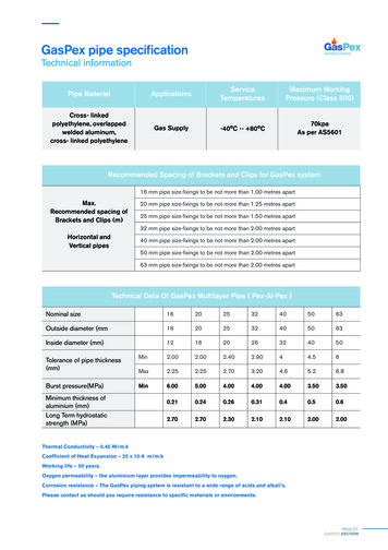
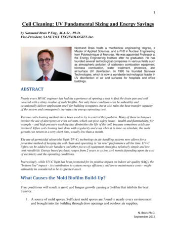
17UV Intensity Design Level for Coil CleaningAs we all know, light intensity varies significantly with the distance from the lamps. In addition,the physical geometry, number of lamps, and UV lamps positions all have the potential to affectthe overall distribution of the UV intensity on a given coil. Only a computerized program usingan integration method and summation of the contribution of all the UV lamps allows to preciselycalculate the UV irradiation field on a coil face.Many manufacturers size systems by rules of thumb, such as filling the available crosssection with an almost continuous array of lamps at a constant spacing, or base their designson limited proprietary testing. Unfortunately, these rudimentary rule of thumbs often end upusing too much or too little UV intensity, which either makes the UV coil cleaning technologytoo expensive or deceptively inefficient at keeping the coil free from biofilm nuisance.The following image illustrates the typical output provided by a proper UV sizing software.InstallationCoil WidthCoil HeightDistance between lamp and coil120 in120 in18 inLamp LengthNumber of RowsNumber of Lamps per RowLamp Position on Coil*Lamp Fouling**Lamp Fouling will occur on a Downstream Installation40 in22Survival time of660,1-776,21124,5-1240,61588,9-1705545 µW/cm221102 µW/cm1705 µW/cm2776,2-892,31240,6-1356,7486072Coil width, W [in]8496108
Number of Tube Rows 8 Increase fan power due to coil fouling 0,526 kW Coil effective area 21 454 ft2 Clean coil heat transfer coefficient 7,32 BTU/hr.ft2.R Air flow 29 150 ACFM Fouled coil heat transfer coefficient 5,78 BTU/hr.ft2.R Air velocity between fins 428 ft/min Heat tranfer reduction due/biofilm fouling 21,0%