Transcription
CI/SfBXt6August 2003PRECAST LIFTING AND FIXING SYSTEMSCONCRETE
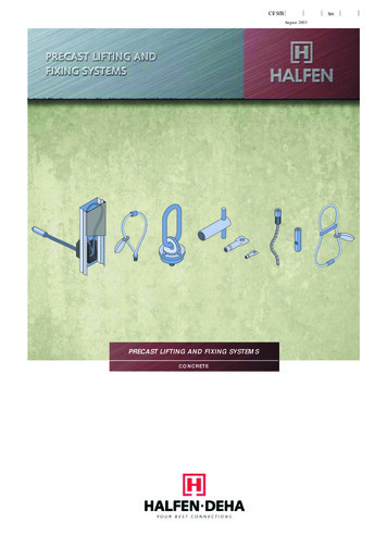
HALFEN2PRECAST INSERT SYSTEMSCONCRETEIntroductionThis brochure details Halfen products for the precast industry. In particular,it gives guidance to the design team indicating how to demould, transportand erect precast concrete units by using the threaded/wire ropesystems. The work involves serious Health and Safety considerations andit is unwise to lift concrete without a completely co-ordinated lifting systemwhich has been developed and tested by a specialist.The basis of the system is a special cast-in socket which is easy to installin the precast yard and easy to recess if extra cover is required. Plaininserts and capped inserts depend on reinforcement tails providedseparately, but wavy tails are factory finished with the wavyreinforcement. The effect of normal reinforcement in the precastcomponent is explained in the brochure.To make this brochure a comprehensive guide for precast design, wehave also included details of normal fixing sockets and a unique wallpanel connection system.Autocad drawings of Halfen components are available on request.Wire rope threaded lifting loopsSwivel lifting eyesFixing sockets08705 316300Panel connection systemFAX08705 316304
HALFENPRECAST INSERT SYSTEMS3CONCRETEContents and selection chartPageLifting systems – threaded8Wavy Tail lifting insert– Socket swaged to anchorage; ready to use; safe and quick– Available in12 – 52mm diameters, giving load capacity of 500 – 12,500 kg– Use with Threaded lifting loop or Swivel lifting eye10Plain Socket lifting insert– Reinforcement tail must be installed in the yard; tail may improve anchorage– Available in12 – 52mm diameters, giving load capacity of 500 – 12,500 kg– Use with Threaded lifting loop or Swivel lifting eye12Capped End lifting insert and Screw Anchor insert for thin units––––Low profile socket fully welded to plate; reinforcement must be installed in the yardUsed in the face of thin units and for long term reuse for maintenanceAvailable in12 – 52mm diameters, giving load capacity of 500 – 12,500 kgUse with Threaded lifting loop or Swivel lifting eyeAll the above are available in mild steel BZP or stainless A4, but in most caseswhere stainless is required the Capped End lifting insert is the preferred optionThreaded Lifting loop and Swivel Lifting Eye14 & 16– Suitable for all inserts above– Threaded Lifting loop is for single use– Swivel Lifting Eye is for multiple use; must be used where pitchingFormers to locate inserts on formwork15 & 17– Also used to form recess to provide extra cover.– If for eventual use by Swivel Lifting Eye, then former diameter is criticalLifting systems – cast in hoops18Cast in wire hoops– Steel wire swaged to form a loop; can be cast into concrete without additional tail– Load capacity 800 – 25000 kg; large sizes easily made to order– Use with standard crane hook; normally cut off after use18Cast in polypropylene hoops– Economic lifting for small components up to 1200 kg– Cut off after use; no corrosion problemsFixing systems20Fixing sockets– Point fixing for precast or insitu work– Ready for set screws22Panel connection system– For connecting precast wall panels– Easy to cast in the yard; safe for rebending– Quick to use for insitu stitch on site08705 316300FAX08705 316304
HALFEN4PRECAST INSERT SYSTEMSCONCRETEDesign considerationsGeneral guidance for all liftsSpecific guidance – threaded systemsEnsure that the concrete is at least 15 N/mm2 strength beforelifting. If the lift must be made at a lower strength, please consultHalfen Ltd.For plain sockets with a hole,specify a reinforcing tail asshown on page 11.For most lifting applications, the ‘factory finished’ Wavy Tail insertis the first choice. When positioning inserts, always check thepermitted edge distances and spacings – for drawing assistancea Halfen Autocad disk is available.Reinforcement tailIf an angled lift is to be used, try and restrict the angle β to amaximum of 30 .Consider how frequently the unit is to be lifted. For repeated liftson the same insert, a Swivel Lifting Eye may be the best option, inwhich case, specify a recess former – see page 17. For one-offuse, specify the Threaded Lifting loop – for this the inset may becast flush or recessed for corrosion protection. Check that therecess complies with the cover specification on the job.If the tail has to be cranked inthin units, specify reinforcementas shown on page 11. Do notuse flat tails.Crankedreinforcement tailGeneral guidance – Threaded systemsThe lifting inserts in this catalogue have a type Rd thread, which isa slightly modified metric thread. The Threaded Lifting loops andSwivel Lifting Eyes have Rd/M threads, which means that they fitboth metric and Rd inserts.Lateral reinforcementUse Capped End inserts in thinunits – use stainless steel wherereuse of inserts is planned, eg formaintenance access. Specifyreinforcement tails and check thatthe tail can be accommodatedwithin the edge distance.Reinforcement tailsWavy tail insertNormal fabricreinforcementRecess formed above insert– see pages 15 & 17Swivel Lifting Eyeis usually used inthe precastingyard.Design for reduced loads wheninserts are used to turn/pitch apanel for horizontal to verticalposition – see pages 8 and 9.Do not use a Threaded Liftingloop – always use a SwivelLifting Eye for these applications.YesGeneral guidance – Cast-in wire rope systemsRecess filled with fineconcrete after useA ThreadedLifting Loop isusually usedon site.Wire rope is normally used forheavy lifts. The loop projectsabove the surface of the concreteready for the crane hook. Easy toplace in the cage of largecongested units. Normally has tobe cut off after the unit has beeninstalled.Special note: staircase unitsStaircase units are often lifted into awkward spaces on site andsubject to extreme loads. When selecting inserts for staircases,please contact Halfen Ltd.08705 316300FAX08705 316304
HALFENPRECAST INSERT SYSTEMS5CONCRETETypical applicationsPanelsTurn/pitchDemouldErect/install on siteSpreader beams giving a vertical lift are always the first choice, but if chains are used, resulting in an angled lift, keepβ as small as possible. Always make the full calculation – see pages 6 and 7. Normal setting out is at 1/5 points, butany dimension is acceptable provided edge distances ez and ez/2 are observed – see pages 8 – 19.Terrace n site take care as only two chains may betaking the loadDouble T or bridge beamsAlternative examples – details vary depending onmethod of casting.Architectural stonePolypropylenecast-in hoopCast-in wireloopBeams are very heavy loads, so cast in wireropes are generally the best option08705 316300Architectural features in reconstructed stone are often quitesmall units and economy and corrosion resistance are themain consideration. Polypropylene hoops have a SafeWorking Load of up to 1200 kg.FAX08705 316304
HALFEN6PRECAST INSERT SYSTEMSCONCRETECalculation of Actual Working Loads and arrangement of slingsIntroductionThe loads quoted in the tables in this catalogue are Safe WorkingLoads (SWL) for components cast in 15 N/mm2 concrete. TheSWL has been derived at by applying a safety factor on test dataof 2 for concrete and 3 for steel. These are the maximum loadsallowed on the components.Before selecting any component, it is important to know the ActualWorking Load F of a system. F can be calculated from thefollowing factors: site a factor of 1.5 is more appropriate. However, care must betaken when transporting suspended precast units over uneventerrain where, in the interests of safety, a crane factor of 2should be used.Total loadThe total load of the precast unit for calculating the anchor is asfollows:1. When demouldingV1 (G Ha)fdeadweight of the precast unit (G)adhesion to the formwork (Ha)method of craning (f)angle of pull factor (z)number of loadbearing inserts (n)2. when transportingV2 G x fTaking all these factors into account, the force F at a given pointof lifting can be calculated. This must not exceed the SWL givenin the tables in this catalogue.Note:To avoid tilting of the unit during transport, the load should besuspended such that its centre of gravity S is directly below thecrane hook.DeadweightA lifting beam is the ideal method of lifting if site conditionspermit.The mass G of a precast reinforced consrete unit can bedetermined using a density of γ 25 kN/m2.G total weight of the precast unitAdhesion to mouldAdhesion forces between the mould and the concrete varyaccording to the type of mould used. The following may be takenas a guide:Oiled steel mouldFinished timber mouldRough timber mouldAngle of pullWhen slings are used, the angle of pull β depends on the lengthof the suspending cable. The resulting horizontal componentincreases the tensile force on the anchor by a further factor:Angle of pull factor (z) 1/cos β.q 100 kg/m2q 200 kg/m2q 300 kg/m2The value Ha of adhesion to the mould is thus calculated by thefollowing equation:βHa q x A**A is the area of contact between the mould and the unit being lifted.Higher adhesion to the mould is to be expected for double T-slabsand coffered units. For ease of calculation, a multiple of the massis used:Double T-beamsCoffered unitsHa 2 x GHa 4 x GAdhesion to the mould should be minimised before lifting out ofthe mould by removing as many parts of the mould as possible.Method of craning / Crane factorWhen moving a precast unit, the dynamic forces vary dependingon the type of crane etc. For calculation purposes Halfenrecommend a crane factor as shown below:In the precast yard – demould– pitch– transportOn site – pitch/transport/installffff 1.11.31.31.5Crane factors of 1.1 to 1.3 are to be expected for cranes withprecision lifting, such as those used in manufacturing plants. On08705 316300Angle of pull β0 Angle of pull factor (z)1.007.5 1.0115.0 1.0422.5 1.0830.0 1.16 1.26 1.4137.5 45.0 preferred β 30 Note: For β 45 please consult Halfen Ltd. FAX08705 316304
HALFENPRECAST INSERT SYSTEMS7CONCRETECalculation of Actual Working Loads and arrangement of slingsMultiple slingsFor beams with more than two suspensionpoints and for a panel with more thanthree, it is impossible to work out the loadper anchor precisely, even if the anchorsare arranged symmetrically to the loadcentre. As a result of unavoidabletolerances in the suspension system and inthe position of the anchors, it can never bedetermined whether the load on eachanchor is equal. The use of tolerancecompensating suspension systems (e.g.articulated lifting beam combinations,multiple slings with compensating rig etc.)permits exact load distribution, but shouldonly be used by experienced specialists.Also ensure that if such a system is used,it must be available both in themanufacturing plant and on site. In caseof doubt, only two anchors should beassumed to be loadbearing.Examples for determining the number ofloadbearing anchors:For an arrangement of four independentchains or continuous diagonal chain runs,only two anchors can be assumed to beloadbearing.βGNumber ofloadbearinganchors: n 2A perfect static weight distribution can beobtained by the use of a lifting beam andtwo pairs of anchors set out symmetricallyThe use of three points ensures that thestatic load is shared.βThe use of two anchors is recommendedfor beams and the top of panels. Fouranchors installed symmetrically to the loadcentre are recommended for flat slabs.See the examples illustrated on the right.120 βGGNumber ofloadbearinganchors: n 4Calculations for manufacturingplant and construction siteTo ensure the correct selection, thecalculation must be checked for bothmanufacturing plant and site conditions, asshown below.Number ofloadbearinganchors: n 3This system with compensating rig makes itpossible to distribute the load evenly overfour anchors.Example: slab unitLifting, transporting in the plant and on siteG MassA Mould areaq Adhesion to mouldf Crane factorz Angle of pull factorConcrete strengthManufacturing plantDemouldTransport10,000 kg20m2–200 kg–1.11.31.04 (β 15 )15 N/mm2SiteErect10,000 kg––1.51.16 (β 30 )35 N/mm2With two anchors, the force F per anchor is as follows:Demould at the manufacturing plant:F G (q x A) x f x zn 10,000 kg (200 kg/m2 x 20 m2) x 1.1 x 1.04/2 8008 kgTransporting at the manufacturing plant:F Gxfxzn 10,000 kg x 1.3 x 1.04/2 6760 kgErecting on the construction site:F Gxfxzn 10,000 kg x 1.5 x 1.16/2 8700 kgWhere n the number of loadbearing inserts.08705 316300FAX08705 316304
HALFEN8PRECAST INSERT SYSTEMSCONCRETEWavy Tail InsertsWavy Tail inserts are supplied factory finished and consist of asocket swaged to a wavy reinforcement bar. They are always thepreferred option provided the length and edge distance fit the jobdetail.Standard lengths h1 are shown below. For details of the range ofshort Wavy Tails or straight tails please consult Halfen Ltd.The preferred lift is a β 30 shown below.Materials:Mild steel – socket BZP, tail mill finishStainless – socket A4, tail mild steel mill finishSafe working loads shown are after the application of a safetyfactor on test of 2 for 15 N/mm2 concrete and 3 for steel.Actual working load must be calculated as shown on pages6 and 7.Size, availability and anchorage reinforcementHow to orderaWavy Tailinserts –Code PCinsert typeSpacing of inserts/edge distanceIf recessrequired,see pages15 & 17for detailscdinsert materialthread sizeh1insert heightezLong/shorterPC2 20257Lerez2Dimensions are subject to cage or fabric reinforcementbeing used, as shown opposite.Order codeSizeRd12Rd16Rd20Rd24Rd30Rd36Rd42Rd52Mild steel – BZP/Stainless imensionsdammmmcmmh1mmSWL for 15Nconcrete strengthkgMinimum ermmMinimum ezmmNormal reinf.main bar 27010088012,500138120020Minimum er assumes cover to the reinforcement is acceptableto the designer: stainless steel may be needed if cover islimited.Summary calculations – details page .Yard, e.g. demouldwhere:F G (q x A) x f x ZnF load per insert when liftingSite , e.g. erection(usually the worst case)q x A adhesion to the mouldLifting on site is usually the worst case due to higher cranefactors and worse angle of lift (β) – see calculation page 7.F GxfxZnZ factor for angle βFor panels with a single layer of fabric, ie for vertical lift andno pitching, please consult Halfen Ltd.i.e. factors f and Z areusually worse on siteSpecial minimum er may be agreed with Halfen Ltd on a jobbasis.For recess former for Swivel Lifting Eye, see page 17.For recess former for increased cover, see pages 15&17.08705 316300FAXG dead weight of unitf crane factorn number of inserts08705 316304
HALFENPRECAST INSERT SYSTEMS9CONCRETEWavy Tail InsertsThe details on these pages show panels, but they could equallyapply to other components. The loads shown assume the angle oflift, i.e. β 30 and normal reinforcement, such as a cage or twolayers of mesh. For a single layer of mesh please consult HalfenLtd. Erecting panels reduces the allowable load as shown below.Typicalpanelsβ 12.5 Reinforcement cageTypically T12 bars full length andT8 stirrups at 150 mm centresβ 12.5 Two layers of meshTypically 8 mm wire, such as A252 and B503Lateral reinforcement for β 12.5 45 Turning reinforcement for slabsWhere the lifting angle, is between 12.5 and 45 ,additional reinforcement is required as shown below.When turning/pitching additional reinforcement isrequired. Note: β must not exceed 30 20 Turning reinforcementDetail shows position oflateral reinforcementInsertdia. reinforcementdia.unbent length128500 168500 2012800 2412800 301236Longitudinal bars forlarger sizes – see tableInsertdia.Turningreinforcementdia. unbent lengthLongitudinalbarsdia.length128700not required1681000“20121200“24121300“800 30121500“161500 36161800“42161500 421620001660052161500 5216200016600Allowable SWLas table shownoppositeez/2 may increase slightly to accommodate these bars.1. Even with the reinforcement shown above, the allowableSWL is 50% of that shown in the table opposite.2. Swivel Lifting Eye is essential – Threaded Lifting Loop is notpermitted.permitted08705 316300FAXNotpermitted08705 316304
HALFEN10PRECAST INSERT SYSTEMSCONCRETEPlain Sockets and Crimped SocketsPlain Sockets and Crimped Sockets are economic and haveadvantages in thin components, where the long tail providesexcellent anchorage. The reinforcement tail is essential and mustbe installed as shown in the yard by the precaster.For thin units that have to be turned through 180 from mould tofinal position, plain sockets can be made double threaded to passright through the unit.Plain Sockets are available in mild steel BZP and stainless steelboth with Rd threads. Crimped Sockets are only available in mildsteel BZP and with metric threads. The sockets are specially madefor lifting are not to be confused with fixing sockets.Safe working loads shown are after the application of a safetyfactor on test of 2 for 15 N/mm2 concrete and 3 for steel.Actual working load must be calculated as shown on pages6 and 7.Size, availability and anchorage reinforcementCrimped Sockets – Code PBPlain Sockets – Code PAaaccReinforcementtailhhTailbOrder codeMild steel – BZP/Stainless steelbDimensionsabmmmmcmmhmmSizeOrder codeMild steel – BZPRd12PA2 12042PA8 1204215.08.02240M12Rd16PA2 16054PA8 1605421.013.02754Rd20PA2 20069PA8 2006927.015.535Rd24PA2 24078PA8 2407831.018.0Rd30PA2 30103PA8 3010339.5Rd36PA2 36125PA8 36125Rd42Rd52SizeDimensionsabmmmmcmmhmmSWL in15N/mm2 concretekgPB2 1205516.510.02055500M16PB2 1607622.013.02076120069M20PB2 2009027.015.0259020004378M24PB2 2410531.017.030105250022.556103M30PB2 6300PA2 42145PA8 4214554.032.080145–––––8000PA2 52195PA8 5219570.040.0100195–––––12,500Spacing of sockets and edge distancesezez3e r2ererTypical thick panel or beamezmin ez (mm)Rd12 / M1237300Rd16 / M1640400Rd20 / M2050550Rd24 / M2460600ezRd30 / M 3 0706502Rd36100800Rd421201000Rd521381200Typical slab or culvertNote: The dimensions assume cage or fabric reinforcement as shown at the top of page 9For help with setting out, use the Halfen Autocad disc.08705 316300min er (mm)SizeFAX08705 316304
HALFENPRECAST INSERT SYSTEMS11CONCRETEPlain Sockets and Crimped SocketsThe details on these pages show panels, but it could equally applyto other components. The loads shown assume the angle of lift, i.e.β 30 and normal reinforcement such as a cage or two layers ofmesh. For a single layer of mesh please consult Halfen Ltd. Turning/pitching panels reduces the allowable load as shown below.Typical slabFabric/matreinforcement isessential.TypicalpanelsTailβ 12.5 Reinforcement cageTypically T12 bars full lengthT8 stirrups at 150 mm 252519612002500Lateral reinforcement for β 12.5 45 AnchoragereinforcementWhere the lifting angle, is between 12.5 and 45 ,additional reinforcement is required as shown below.20 Tail tightto bottomof theholePlain orCrimpedSocketDetail shows position ofreinforcementDLdmmReinforcement tails should normally be U bars, however,in slabs the anchorage reinforcement may be cranked asshown. A completely straight bar should be avoided.Bars must be laid over the cranked bars as shownβ 12.5 Two layers of meshTypically 8 mm wire, exampleA252 and B503dinsertdia.60 appproxReinforcementtailMinimum er assumes cover to the reinforcement is acceptable to thedesigner: stainless steel reinforcement may be needed if cover islimited. Special minimum er may be agreed with Halfen Ltd on a job basis.reinforcementdia. unbent length126400 168650 208 9002412950 30121200 36161500 42161700 52202100 Allowable loadas main tableshownoppositeez/2 may increase slightly to accommodate these bars.For recess former for Swivel Lifting Eye, see page 17.Turning/pitching reinforcement for slabsFor recess former for increased cover, see pages 15 & 17.Lifting on site is usually the worst case due to higher crane factors andworse angle of lift (β) – see calculation page 7.Additional reinforcement is required where sockets areinserted in the edge for turning/pitching. See page 12 fordetails. Note that even with the additional reinforcement, theSWL is 50% of that shown in the table opposite.For panels with a single layer of fabric, ie for vertical lift and nopitching, please consult Halfen Ltd.08705 316300FAX08705 316304
HALFEN12PRECAST INSERT SYSTEMSCONCRETECapped End Lifting InsertsCapped End inserts are low profile (see h in chart below) andhence are ideal for the face of thin panels or top of slabs. Thesocket and cap are fully welded so the socket is effectivelysealed.Preferred angle of lift β 30 . If the insert is to be cast in arecess see pages 15 and 17.Capped End inserts are available in mild steel BZP and stainlesssteel A4. When supplied in stainless steel, the capped end helpsprevent water ingress and corrosion.Actual working load must be calculated as shown on pages6 and 7.Safe working loads shown are after the application of a safetyfactor on test of 2 for 15 N/mm2 concrete and 3 for steel.Size, availability and anchorage reinforcementCapped End Lifting Inserts – Code PGSpacing of insertsaIf recessrequired, seepages 15 & 17for detailsNormal 0Rd36Rd42Rd52Order codeMild steel – BZP/Stainless z2er1etbxcmmtmmSWL in15N/mm2 concretekger2Min. er1 Min. ez1 Min. er2 Min. ez2mmmmmmmmMin. etmm15.03025 x 354500180360651157021.03535 x 5041200250500751408527.04760 x 7570.0117130x1501012,5007501500190435215Minimum er1 and er2 assumes insert is within the normal cagereinforcement. Cover to the reinforcement must be acceptable tothe designer: in some cases stainless steel may be needed.Summary calculations – details page .Special minimum er1 and er2 may be agreed with Halfen Ltd on ajob basis, for example if unit to be lifted is 30 N/mm2.F G (q x A) x f x ZnFor recess former for Swivel Lifting Eye, see page 17.For recess former for increased cover, see pages 15 & 17.Lifting on site is usually the worst case due to higher crane factorsand worse angle of lift (β).Yard, e.g. demouldwhere:F load per insert when liftingG dead weight of unitq x A adhesion to the mouldSite – handlingf crane factorF GxfxZnZ factor for angle βn number of insertsi.e. factors f and Z areusually worse on site08705 316300FAX08705 316304
HALFENPRECAST INSERT SYSTEMS13CONCRETECapped End Lifting InsertsStainless steel socket withplastic sealing cap – seepage 17.The details below show thin units such as slabs and panels.Capped End inserts are ideal for use and re-use, such as accesspanels which are to be removed for maintenance. In this case arange or permanent caps are available. Capped End inserts arenot normally used for turning/pitching, but should an applicationarise, please consult Halfen Ltd.All sockets may be temporarily covered using a plasticsealing cap – see bottom of page. Where regular use ofan insert is required, Halfen produce special threadedsteel sealing plates to suit the design detail.Reinforcement tailsEssential withall cappedend insertsSteel sealing plate screwsinto insert to keep it cleanready for re-useNormal reinforcementmain bars and stirrups– see table belowLateral reinforcement for βIn addition to the normal cage and tails, lateralreinforcement is required for angles 12.5 45 – asshown below:d30 12.5 45 aDetail of reinforcement tailNormal reinforcementMain barsFabricdia. 1401140Rd3616A252161401250Rd421612mm bars201601530Rd522012mm barsDetail shows positionof reinforcementInsertdia. Reinforcementdia. unbent length128500 168500 2012800 2412800 3012800 36161500 42161500 52161500 AllowableSWL astable shownoppositeIf lateral bars are needed at min. er1 min. er2 please consultHalfen Ltd.Screw anchor insert – Code PT Mild steel bright zinc platedThreaddiameterScrew Anchor inserts are suitablefor shallow embedment withoutthe need for a reinforcement tail.Lateral bars needed as above forangled lifts.hOrder code DimensionMild steel BZPh mmSWL in 15N/mm2concrete 002000Rd24PT2241151152500Rd30PT2301001504000For stainless steel please contact Halfen Ltd.08705 316300FAX08705 316304
HALFEN14PRECAST INSERT SYSTEMSCONCRETEThreaded Lifting loopIntroductionThreaded Lifting loops can be used with all sizes of threadedinserts. They are the most economic lifting loop and are suitablefor most applications, particularly site operations. They are notsuitable for turning/pitching. They may be reused subject to theinspection procedure, detailed below, but they are notrecommended for severe re-use conditions.Size and availabilityThreaded lifting loop – Code PXThreaded Lifting loops should only be attached to the unit after theconcrete strength has reached 15 N/mm2. In some cases it maybe economic and practical to leave the loops with the unit untilfinal installation.Colour codedtag indicatesSWL and sizeDescriptionThreaded Lifting loops are manufactured from high grade steelwire, swaged in a steel ferrule and finished with zinc plating.They are clearly marked with their SWL. The thread type isRd/M, which is compatible with both metric and Rd inserts.hThreaded Lifting loops are suitable for use with inserts cast in flushwith the face of the unit, or recessed using the recess formersshown opposite.stTesting/identificationAll Halfen devices are proof loaded before dispatch and labelledwith a unique code number. This number is recorded in the QAdepartment at Halfen Ltd. If loops are kept in the stores and reusedthey must be inspected every six months and retested every year.Method of useBefore use, check that the lifting loop is compatible with thesocket/insert and labelled with the Halfen unique number.Check that the wires are in good condition. Discard if bent,crushed, kinked or if there is any loosening of the outer layer.Discard if corroded.Check the angle of lift shown on the unit drawings and follow theprocedure shown. Do not use Threaded Lifting loops for turning/pitching a unit. If β exceeds 45 , please consult Halfen Ltd.SizeOrder Full 715536RedRd/M20PX2020003521545Light 30068Dark 5GreyRd/M52PX5212,50095480117YellowEnsure that the thread is fully bottomed out in the socket beforelifting. It is permissible to back off one turn to ensure that the wireis correctly aligned for lifting.ApplicationsVertical liftpreferredoptionAngle of liftβ should notnormally bemore than30 βDimensionshsColourcodeNot suitable forturning/pitchingSpreader beamhelps to reduceangle of liftβ08705 316300tFAXβCheck that theradius of thehook is at leastthe diameter ofthe rope08705 316304
HALFENPRECAST INSERT SYSTEMS15CONCRETERecess formers for Threaded lifting inserts(for eventual use with Threaded lifting loops)IntroductionThreaded inserts must be carefully fixed to formwork, ie, correctlylocated and held firmly. Halfen offer a range of fixing methods.Any of the fixing methods shown below is suitable for use with theThreaded Lifting loop, but plastic nailing plates are the mosteconomic and hence the most commonly used.For improved corrosion protection of the socket after use, iedeeper recess, please use the small deep nailing plate, Code PXD.Size and availabilityPlastic nailing plateCode PXNPSmall deep nailing plateCode PXDMagnetic nailing plateCode PXMNPyyyxxxMost suitable choice if a minimalrecess/cover is acceptable.This plastic nailing plate is suitable forboth metric and Rd threads.The recess gives minimal cover, ie, itmay not be deep enough to resistcorrosion.Nail to formwork and screw onsocket.After stripping, unscrew. Not normallyreusable.OrdercodeWidthx (mm)Depthy Rd/M24PXNP24Rd/M30A plastic insert for use where greatercover to the socket is required. Therecess gives 15mm cover.The small diameter means that anysubsequent filler is less conspicuous.It is suitable for both metric and Rdthreads.The recess gives 15mm cover.It is suitable for both metric and Rdthreads.Place on steel formwork and screw onsocket.Nail to formwork and screw on socket.Reusable – after stripping, unscrew,clean and store on a keep plate.After stripping, unscrew. Not normallyreusable.Removing toolPXDNPK isavailable ifrequired.OrdercodeWidthx (mm)Depthy 2Rd/M42PXNP4211515Rd/M52PXNP5213515SizeA magnetic nailing plate for use onsteel formwork.Removing toolPXMNPK isavailable ifrequired.OrdercodeWidthx (mm)Depthy �––––––––Size08705 316300FAXSize08705 316304
HALFEN16PRECAST INSERT SYSTEMSCONCRETESwivel Lifting EyeIntroductionSwivel Lifting Eyes can be used with all sizes of threaded insertsand are specially designed to allow angled lifts, such asturning/pitching. They are more durable than wire lifting loopsand may be used repeatedly, subject to inspection for damage.They should only be attache
Design considerations 08705 316300 08705 316304 FAX General guidance for all lifts Ensure that the concrete is at least 15 N/mm2 strength before lifting. If the lift must be made at a lower strength, please consult Halfen Ltd. For most lifting applications, the 'factory finished' Wavy Tail insert is the first choice.

