Transcription
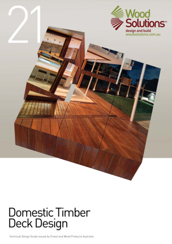
Design and Constructionof a Buried PrecastPrestressed Concrete ArchC. James Montgomery,Ph.D., P.Eng.PartnerThe Cohos Evamy PartnersEdmonton , Alberta, CanadaFormerly with Lamb McManusAssociates Ltd.R. M. Morison, P.Eng.Specialist ConsultantReid Crowther & Partners Ltd.Edmonton , Alberta, CanadaFormerly with Lamb McManusAssociates Ltd.J. R. Channen, P.Eng.Acting Director, Bridge DesignAlberta Transportation and UtilitiesEdmonton, Alberta, CanadaThis paper describes the design, manufactureand construction of a buried precast, prestressed concrete arch, with a span length of19.6 m (64.3 ft) and an overall length of 173m (566ft), which carries highway traffic overrailway tracks near Obed in Alberta, Canada.In design, a nonlinear finite element analysiswas undertaken to account for the interactionbetween the structure and surrounding soil,as the arch was subjected to backfill andhighway loadings. This allowed the arch wallthicknesses to be reduced substantially whencompared to the thicknesses used in conventional designs. The arch was erected overa Canadian National Rail main line withoutdisturbing railway traffic. The structure wasdesigned to provide Alberta Transportationand Utilities years of service, with maintenancecosts lower than those normally associatedwith highway bridges.buried precast, prestressed concrete arch with a spanof 19.6 m (64.3 ft) and an overall length of 173 m(566 ft) was recentl y constructed near Obed, Alberta, Canada, as part of the enlargement of the YellowheadHighway (No . 16) between Edmonton and Jasper NationalPark. This arch carries highway traffic over two paralleltracks of the Canadian National Railway (see Fig. 1). Thearch is believed to be the longest span structure of its typeconstructed over a rail way line or highway in Canada.A precast, prestressed concrete arch was selected fo r therai lway overpass from considerations of hi ghway trafficsafety, ini tia l cost and future mainte nance costs fo r thestructu re, and the ease with which the hi ghway could beAD. 0. Tutty, P.Eng.Marketing ManagerCanadian Branch , VSL CorporationEdmonton , Alberta, CanadaFormerly with Con-ForceStructures Limited40PCI JOURNAL
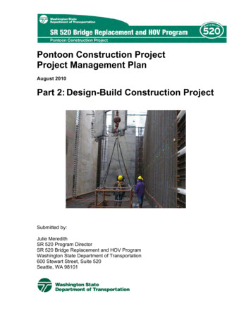
widened in the future. Railway trafficcontinued without interruption duringthe entire construction period.This paper discusses the novel aspects of the arch design and describesthe manufacture and installation of thearch. An important aspect of the paperis that the predicted behavior of thearch is compared to the observed behavior of the structure in the field.The precast concrete arch was designed by Lamb McManus AssociatesLtd . for Alberta Transportation andUtilities. The detailed geotechnical investigation , and the design of surfaceand subsurface drainage measures,were provided by the GeotechnicalServices Section of Alberta Transportation and Utilities .SITE DESCRIPTIONFig. 2 shows the roadway and trackgeometry at the location of the overpass . The highway consists of twoeastbound and two westbound lanes,crossing the twin railway tracks . Aperpendicular to the centerline of thehighway median is on a 62 YJ-degreeskew to the centerline of the railwaymedian.At the location of the overpass, theroadway is on a curve with a 1200 m(3937 ft) radius and has a 5.9 percentsuperelevation. A portion of the railway track median is on a spiral curve,whereas the remainder is on tangent.The geotechnical investigation forthe site indicated that the soil stratigraphy below the level of the railwaytracks consists of an approximately 9m (29.5 ft) thick layer of very stiff,gravelly clay till of medium plasticitywith a water content of 16 percent.The till is underlain by well-cementedsilty sandstone bedrock. In one of thetest holes, water was encountered 7.1m (23 .3 ft) below the original groundsurface.For the clay till, standard penetration test N-values varied from 26 to94 . The till is gravelly, sandy andsilty, with a gray-brown color. Boulders were encountered in the clay tilllayer during drilling .Prebored pressuremeter tests werecarried out for the clay till. The testsgave Young ' s moduli values in the"working" range of 1700 to 3300 tim'January-February 1993Fig. 1. Completed arch.(348 to 676 ksf). The values werelower than expected for till becausethe softer "loading" (rather than "unloading" ) portions of the pressuremeter curves were used in calculatingmoduli . A bulk modulus of about 2000t/m' (410 ksf) was measured in thelaboratory for the till. The sandstonebedrock is silty, fine grained and wellcemented, with a gray color.DESIGN ALTERNATIVESPrior to undertaking the detaileddesign of the precast concrete arch,several design alternatives were considered for the overpass . To minimize snow drifting problems aroundthe railway tracks in the winter ,Canadian National Rail expressed apreference for the use of a continuous underground structure to supportthe highway .The Bridge Engineering Branch ofAlberta Transportation and Utilitiesalso expressed a preference for an underground structure because it wouldbe better suited to handling the complex roadway geometry at the overpass. They felt that a conventionalbridge at the site could be a hazardduring the winter, owing to the potential for preferential icing of the superelevated and curved deck surface.They also expressed a preference forstructural alternatives that wouldallow for the easy future addition ofone traffic lane in each direction onthe median side of the westbound andeastbound lanes.The following alternatives wereconsidered:1. Buried structure with Rein-forced Earth retaining wallsThis alternative would consist of precast, prestressed concrete box sectionsspanning between cast-in-place concrete footings , which would be supported on Reinforced Earth* fill on either side of the tracks. The precast boxsections would span perpendicular tothe railway tracks, and would be covered by soil fill. Reinforced Earthwalls would retain soil on either sideof the tracks and at the entrances tothe underground structure.2. Buried structure with cast-inplace concrete retaining walls This alternati ve would consist of precast, prestressed concrete box sectionsspanning between ribbed concrete retaining walls. The retaining wallswould be supported by spread footingsbelow the level of the railway tracks .To resist the horizontal reaction fromsoil pressures at the bottom of the retaining walls , round HSS sectionswould be jacked under the railwaytracks at the footing level. ReinforcedEarth wing walls would be used at theentrances of the underground structureto retain soil.* Re inforced EarthTM is a syste m in whi ch me ta l stripsare introduced in the gra nul ar backfill be hind retain ingwall s. The metal stri ps res ist the tensile stresses th atdevelop in the bac kfill owi ng to applied loads.41
72.847I I-- SLOPE TO EXISTING DITCH0TOE Of SIDE SLOPESCALEI0IJQc.0c:Ilz'{::.Fig. 2. Roadway and track plan at location of overpass.20I50I40mI100ftIIEDIAN CNR
c.Ill:::JcIll- -n CNR MEDIANSYM. 1 0"2Ill- D DwI,1III --1 IlIIGROUT0It)ll)2300411 50RP.G. PRESSURE GAGEDIMENSIONS IN mmI mm 0.03937 in .19 OYWIOAGiHREAOBARS150015009775FTG.f:,Fig. 3. Arch cross section .
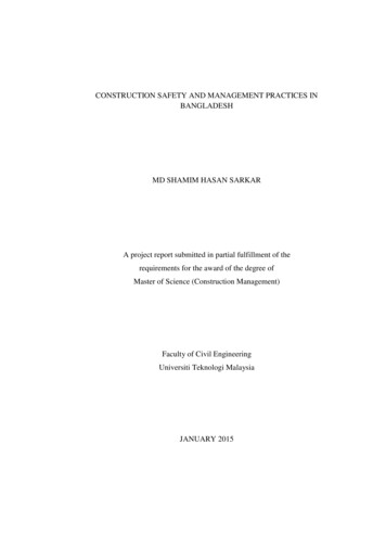
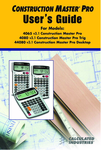
footings below the level of the tracksfor vertical support and soil pressureson the sides of the arch segments forlateral support. The arch seg mentswould be cast in easy-to-handlelengths and erected sequentially. Headwalls with a cast-in-place concretefacing in front of Reinforced Earthand Reinforced Earth wing wallswould be used at the entrances to thearch structure to retain the approachand roadway fills.Table 1. Cost comparisons(1987 Canadian dollars) .EstimatedconstructioncostAlternative designsI. Buried structure withReinforced Earthretain-ing walls 4,394,0002. Buried structure withcast-in-place concreteretaining walls 4,849,0003. Precast concrete arch 3,721,0004. Bridge structure withReinforced Earthabutments 3,516,0005. Conventional bridgestructure4. Bridge superstructure withReinforced Earth abutments This alternative would consist of twinsingle-span bridge superstructures extending parallel to the roadway between Reinforced Earth abutments.One superstructure would be requiredfor the eastbound lanes and a secondfor the westbound lanes. To achievethe proper roadway profile and grades,steel girders with variable thicknesscast-in-place concrete decks would beused for the bridge superstructures.The potential for settlements of the superstructures would be reduced by 3,758,0003. Precast concrete arch - Shownby Figs. 1 and 3, this alternative wouldconsist of two precast concrete arcs ofa circle that are connected together atthe top to form an arch. The archwould rely on reinforced concrete8 . LOAD CASE43'"'"' 5.82 ,tlm2COMPACTED CLAY TILL@3.81l2llll timl ll ll l0.69 13.66GRAVEL .az10. 13.810. 8 . .8ZllZ.l35. Conventional bridge structure Thi s alternati ve would consist ofthree-span, continuous steel girderssupported by conventional piers andabutments . One superstructure wouldbe required to span parallel to the eastbound lanes , and a second, parallel tothe westbound lanes.Table 1 presents the estimated construction costs for the five alternativesat the time the preliminary engineeringreport for the project was prepared.From consideration of initial cost, traffic safety and future maintenancecosts, the precast, prestressed concretearch alternative was selected for theoverpass. The bid cost for the totalproject in 1988 was 3,900,000 (Canadian), including 1,799,000 for theprecast concrete work.DETAILED DESIGNBy conventional design, a concretearch subjected to highway traffictimll3. r3. 1. 1 .3 supporting the substructures on pilesat the abutments.timDIMENSIONS IN mI m 3.281ftlt/m2 0.672kip/ft11/m 0.204 9 ksfCRUSHEDGRAVEL\!\!- "' .r. .0I0Z7.6z,.3 ! ! ! -- v.Z 6;o----- ,.-- -- - - - -t-v-rz oz .3Z3. 1ZI .T'l:l----- -,.lJ.,. -t-- - - --11/-J'.:o-----1---- -- - - , /zo.z.:o----- --- -- - 1118.,.:o----- --- -- - -1CONCRETE"'1,\c -- -- - -- ! - - - - - l - - ----- :J ' \- - - -- - - - - - --0 @8 f-:u E ! gJ t t HNATIVE CLAYTILL 1,.7CIRANUL.ARBACKFILL15.0013. NATIVECLAY TILL r.:. 3rz;o----- --- -- - - - - -- --t----- --t--t--t--t--t--- --- ------o::1'--CONSTLAYER10.5 @-------- 0 ., ------ ---- --- - - - -- ---- ----r-- --- ----- ----- SANDSTONEG)0rl rl,.,.0'Z.5--xFig. 4. Finite element mesh .44PCI JOURNAL
with 0.4 to 2.5 m (1.3 to 8.2 ft) of fillabove it with the span shown in Fig. 3would have had wall thicknesses inthe range of 600 to 900 mm (24 to 36in.). These large thicknesses would berequired to resist the bending momentsfrom soil pressures and highway traffic loadings, with relatively smalldeformations.The precast concrete arch used forthe railway overpass near Obed, Alberta, has wall thicknesses that are inthe range of 300 mm ( 11.8 in.) (seeFig. 3). To achieve these substantialsavings in materials, transportationcosts and erection costs, it was assumed that the arch would interactwith the surrounding soil to resistloads. The arch is relatively flexible sothat large bending moments do not develop as the structure displaces and interacts with the surrounding backfill.In the early 1980s, soil-structure interaction was considered in the designof precast concrete arches for the firsttime by Hebden.' Hebden designedthree thin-w a lled precast concretearches for the Coquihalla Highway inBritish Columbia, Canada . Thesearches have 20 m (65.6 ft) spans with250 mm (9.8 in .) thick wall sections,and carry the highway over creeks. Incontrast to the clay till at the Obedsite, the footings for the Coquihallaarches were founded on rock.Subsequent to the design of the Coquihalla culverts and the Obed culvertconsidered in this paper, the Reinforced Earth Company Ltd. '·' has introduced the trademarked TechSpanSystem to North America. The TechSpan System consists of 150 to 350mm (6 to 14 in .) thick precast concretesegments which are erected to form athree-point hinged arch. A ReinforcedEarth Company Ltd.' brochure illustrates a 12 m (39.4 ft) wide structureover a railway in Madrid, Spain.Computer ModelThe Obed arch considered herein,and the Coquihalla arches, were analyzed using the NLSSIP computer program developed by Byrne and Duncan. Thi s program uses the finiteelement method to account for thenonlinear response of the soil-archsystem. The soil was modeled by twoJanuary-February 1993dimensional isoparametric finite elements, assuming plane strain andisotropic behavior. The concrete archwas modeled by beam elements.Fig. 4 shows the finite elementmodel of the Obed arch and surrounding soil. The arch was loaded incrementally by assuming that the soil wasplaced sequentially in construction layers 1 through 9. Within each load increment, the structural response was assumed to be linear. To approximatenonlinear and stress-dependent soil behavior, the elastic properties of the soilwere adjusted in accordance with calculated stress levels after the placementof each construction layer. Althoughgeometric nonlinearities were accounted for, the arch beam elementswere assumed to have the same elasticproperties for all load increments.The soil response was representedby a tangent Young's modulus, ,, anda tangent bulk modulus, B using thefollowing expressions:E Kpa[ 1rx2l- R1 (1-sin ) )(0 1 -0 3 )][2c cos ) 20 3 sin ) (l)and(2)In Eq. (1), K is the modulus number,n is the modulus exponent, R1 is thefailure ratio, Pais atmospheric pressureexpressed in the same units as stresses,0 1 and 0 3 are the major and minorprincipal stresses, and c and ! are theMohr-Coulomb strength parametersof cohesion and angle of internal friction . The development of Eq. (l) is explained by Duncan and Chang.'Duncan et al. 6 indicate that the angleof internal friction to be used in Eq.(1) decreases in proportion to minorprincipal stress in accordance with thefollowing expression:where l o is the value of the angle ofinternal friction at a minor principalstress equal to atmospheric pressureand .tl ) is the reduction in the angle ofinternal friction for a tenfold increasein the minor principal stress.In Eq. (2), is the bulk modulusnumber and m is the bulk modulus exponent. The development of Eq. (2) isexplained by Duncan et al. 6Table 2 presents the parameters recommended by the Geotechnical Services Section of Alberta Transportation and Utilities for the various typesof soil shown in the finite elementmodel in Fig. 4. The earth pressure coefficients given in the table were usedto evaluate the initial stresses in thefoundation and each newly placedlayer of soil during backfilling.To account for various degrees ofcompaction, three sets of soil parameters were considered for the pit rungravel backfill. A controlled pit rungravel backfill was specified for theproject, since it was necessary toachieve both adequate compaction anddrainage around the arch structure.Table 3 presents representative values of the tangent Young 's modulus,tangent bulk modulus and angle of internal friction for the so il materialsaround the arch. These values werecalculated for major and minor principal stresses equal to atmospheric pressure, which is equal to 10.33 t/m '(2. 12 ksf).The Young's and bulk moduli implied by the parameters given in Table2 for Material 2, native till, were about2 to 2.5 times greater than those justified by the laboratory and field test results referred to previously.Although the test results werejudged to be too low by the geotechnical specialist, the strength of the culvert was also checked assuming amodulus number of 400, a modulusexponent of 0, a failure ratio of 0.75, abulk modulus number of 200, a bulkmodulus exponent of 0 , a cohesion of3 t/m' (615 psf) , an angle of internalfriction of 22.5 degrees at a minorprincipal stress equal to atmosphericpressure, a reduction in angle of internal friction of 0, and an earth pressurecoefficient of 0.7 for the native till.For the concrete arch, an effectivemoment of inertia of 0.25 times thevalue calculated from the gross concrete section was used in the computer45
Table 2. Properties of soils, concrete and ytillSoilaroundfootingsCompactedclay tillConcretePit run gravelCrushedgravelStandard Proctor density (percent)IOO 9590Unit weight (tim' )2.142.142.242.242.42.322.242.162.16Unit weight (pcf)134134140140150145140135135Modulus 0.340.50.40.4Modulus exponentFailure ratio0.60.750.70.700.60.70.70.7Bulk modulus number2400450175175124,00072045017575Bulk modulusexponent0.2500.30.300.250.250.20.2Cohesion (tim')2.550002140000Cohesion (psf)52200043,8000000Angle of internalfriction (degrees)503732321551414235Reduction in angleof internal .50.75Earth pressurecoefficient* See Fig. 4 fo r location in computer model.Table 3. Representative values of moduli and angle of internal friction.Material*I2ParameterSandstoneNativeclay till4Compactedclay till6Pit run gravel(Density 95 percent)Tangent Young'smodulus (tim' )41 ,300847046508780Tangent Young' smodulus 250373241Tangent bulkmodulus (tim' )Tangent bulkmodulus (ksf)Angle of internalfriction (degrees)* See Fig. 4 for location in computer model.model for the beam elements (seeFig. 4). An effective moment of inertiawas used to account for increases inflexibility owing to cracking, creepand shrinkage effects.In the computer model, the footingswere allowed to deflect and rotate asthe surrounding soil elements deformed under load.For strength calculations, load factors of 1.3 and 0.98 were used for soil46placed in layers above the footingsand for the self-weight of the arch, respectively. Load Case 1 in Fig. 4 is forunbalanced fill on the arch. The truckloads shown for Load Cases 2, 3 and4 are for a MS300 (HS33.7) truck,assuming a load factor of 2.17 and a3.7 m (12ft) lane width. Although theroad crosses on a skew, for design itwas conservatively assumed thattrucks cross perpendicular to the Ion-gitudinal axis of the arch .To account for a total backfill depthof 2.5 m (8.2 ft) above the crown ofthe arch at certain locations along thelength of the structure, for some of theresults presented, an additional surcharge load of 3.36 t/m 2 (0.69 ksf) wasadded to the loads shown in Fig . 4.This surcharge load accounts for 1.5 m(4.9 ft) more backfill than is represented by the model shown in Fig. 4.In the analysis , the displacementsand stresses in the soil and the displacements, forces and moments in thearch were recorded after each layer ofsoil (from Layers 1 through 9 inFig. 4) was added. This simulates theresponse of the soil-structure system asbackfill was placed. The correspondingdisplacements, stresses, forces and moments were also recorded after eachload case was considered.Results of Computer AnalysisFig. 5 presents the total factoredbending moments for the concretearch as the soil layers are added duringbackfilling. These moments were calculated using the Table 2 soil properPCI JOURNAL
8(0)020103040I0 /,7E"E(f)1-- 5I' -I 0,-15z''w 0w'' , I/III I'I·,"', /-2060"""·,,'-- .'',.1-90--03·105,,.- -30 '-' ·;.- -40- -50- -60\ r' ":L-30 --25-'.a.,---- -- -- ----07lI ---so-70 lLI 00- -20a:080/v,,1\ \'-X''V-,.-/ -70 /- 0//' I50-35-40CONSTRUCTION }LAYERFig . 5. Sample bending moments du ri ng backfilling .ties with pit run gravel backfill compacted to 95 percent of Standard Proctor density. T he angle 8 is measuredrelative to th e top of the left-h andfoo ting in Fig. 4. Moments are positive if they result in compression onthe outside fiber of the arch.Fig. 6 shows the increme ntal factored bending moments for the unbalanced soil and truck loadi ngs describedin Fig. 4. Although a non linear analysis was used, the incremental momentsof Fig. 6 can be added to the momentsfor Layer 9 in Fig. 5 to obtain an approximation of the combined moments8(0)0I0203040for the various loading conditions.One might anticipate that rock is required below the footi ngs of an arch tooffer enough restraint to sustain negative moments at the junction betweenthe bottom of the arch and the tops ofthe foot ings . It might be anticipatedthat the clay till founding material atObed is not stiff or strong enough toresist negative moments.Even though the Obed structure isnot founded in rock, the geometry andstiffness of the arch and surroundingso il are suc h that negative momentscan be sustained at the junction be-5060708090I 00I I0I 20tween the bottom of the arch and thetops of the footings (see Fig. 5).The factored axial forces in the archfollowing the placement of backfillLayer 9 were 58, 70 and 123 tim (39,47 and 83 kip/ft) at angles of 90, 40and 0 degrees, respectively. The incremental factored axial forces for LoadCase 4 (see Fig. 4) were 18, 25 and 19tim (12, 17 and 13 k.ip/ft) at the respective positions on the arch. Load Case 4resulted in larger incremental axialforces than did Load Cases 2 and 3.Fig. 7 show s the computed soilstresses at working load levels assuming that 2.5 m (8.2 ft) of backfill hasbeen placed over the crown of thearch. By way of comparison, assumingan earth pressure coefficient of 0.5 , byconventional calculations one wouldexpect horizontal soi l pressures varying from 0 at the ground surface to13.7 t/m ' (2.8 1 ksf) at the level ofPoint 139 in Fig. 7.An estimate of the soil pressuresund er the footings can be made bysumming the weight of the soil abovethe footings and arch, the weight of thearch and the weight of the footings , anddividing this total by the sum of thefooting areas . By these conventionalcalculations, the soi l pressure wou ld beapproximately 56.3 tim' ( 11 .5 ksf), assuming 2.5 m (8.2 ft) of soi l is abovethe arch crown. The vertical pressuresshown in Fig. 7 are approximately 20percent lower than the pressures obtained by conventional calculations.I 30I 40I 50I 60I 70I 8020L )AD CASE4-.0wa:OEOE/.u.- (·J ((f),--;- '\/101-'-.01-1-zz :,,, ., . ,r--ww woa: -100z//',,-- f.-'/--r-"·,.- ,----·" / /lL,/·\-- ---\.\ - 40-30:::-20 -"-1·0 \'\N.\.-0/ I·,"·v']' ':. : -"r--7'LOAD r.AsE 1 /LOA D CA E 2LpAD ASE 3,,,/- 20,/"'' - --1--, ;.L,0p-/-v'-- 10-- 20-30- 40Fig. 6. Sample bending moments from unbalanced soil and truck loading.January-February 199347
0SURCHARGE 3 36 t1 m0102CONSTRUCTIONLAYER9rI82 83l/7v236v65v43vIO""x(t/m20\2l10 20 30 ""-""- ""-""-'-0\ .82010a;y 20(t/ m2 l 304050-X:I II8139""'II t/m2 0 .2049 ksf/Fig. 7. Soil pressures for backfill 2.5 m (8.2 ft) above c rown .Table 4. Calc ulated displacements at locations a ro und arch.IncrementalTotalPoint*Soil at crown (Layer 8)Xy(mm)(mm)Truck load at crown (Load Case 4)Soil 2.5 m above crownX(rnrn)yX(mm)(mm)y(rnrn)- 1.8829.2- 26.57.8- 43.1- I. I1394.5- 26.51.2- 43.1- 1.2- 1.823612.4- 8.89.7- 33.20.0- 5.82830.026.40.0- 6.01.3- 8.7* See Fig. 7 for locations of displacements.Note: I mm 0.03937 in .; I m 3.28 1 ftThe following are possible reasonswhy the vertical soil pressures underthe footings determined from the computer analy sis are smaller than thepressures obtained from conventionalcalculations:1. The footings are founded on claytill , which is more compressible than48the rock often present for arch structures. As the Obed structure was backfilled, the computer ana ly sis accounted for the settlement of thefootings relative to the adjacent soil.Some of the weight of the soil abovethe structure was transferred by arching action and shear stresses to theadjacent backfill material.2. The pressures from the computeranalysis are determined at the centersof the finite elements, rather than atlocations directly under the footings.lf a finer finite element mesh had beenused, higher vertical press ures mayhave been determi ned from the analyPCI JOURNAL
24402702701130(()(()w00t i li-12 - 50111 I.D. SHEATHS11-- ":.::::.::::.:::.:::.:""-!1-6 - 50111 I.D. SHEATHS(FOR#a8 -DYWIDAG THREADBARS)15M 9 -15M6 - 25MEXTRA6 6 -25M25M 15M 0 4509 -6 4 -4 -20M15M15M 50111 I. D. SHEATHS(FOR 119 DYWIDAGTHREADBARS)SIDE VIEWFig. 8. Typical precast concrete arch segments.DIMENSIONS IN mmI mm 0.03937 in.SEC] ON1980
sis directly below the footings .Working level displacements of theculvert during backfilling were alsocalculated by the computer program.Table 4 I ists displacements at locations around the arch and at the footing for various stages of construction.The points referenced in Table 4 areshown in Fig. 7. The same soil properties were used in the analysis undertaken to prepare Table 4 and Fig. 7.Upon backfilling to the level of thearch crown (Layer 8 in Fig . 7) , thetotal calculated footing settlement was26.5 mm ( 1.04 in.) and the upwardmovement at the crown was 26.4 mm(!.04 in.). With 2.5 m (8.2 ft) of backfill, the total calculated footing settlement increased to 43.1 mm (1.70 in.),but the crown moved 6.0 mm (0.24 in.)below its initial position prior to thestart of backfilling. As shown by LoadCase 4 in Table 4, the calculated incremental displacements for truck loadingwere relatively small.force interaction diagrams for the archwall at all sections . In general, thecomputed axial forces were well belowthe axial capacity of the arch sectionsat balanced load conditions, ensuringductile behavior near failure loads.Arch DesignFig. 8 shows the reinforcing steel arrangement used for a typical arch segment. Concrete with a minimum 35MPa (5080 psi) compressive strengthat 28 days and reinforcing steel with a400 MPa (58 ksi) yield strength wereused to construct the arch segments.The reinforcing steel was selected sothat the moments and axial forces calculated from a large number of computer analyses for various soil conditions were within the moment-axialFig. 9. Footing construction.Connections at theCrown and Footingsand Between SegmentsIn the initial design , the structurewas assumed to be a three-pointhinged arch . Computer calculations indicated that both wall bending moments and displacements would havebeen unacceptably large for the threepoint hinged system. To reduce moments and deflections for final design ,the adjacent arch segments were assumed to be continuous at the crownand rigidly connected to the footings .Figs. 3 and 8 show the thickening ofthe arch segments at the crown and the414 MPa (60 ksi) grade Dywidagthreadbars which were used in conjunction with a grouted longitudinaljoint to achieve continuity.The connection of the arch segmentsto the conventionally reinforced concrete strip footings is also illustrated inFigs. 3 and 8. By connecting the archsegments to the footings with groutedlongitudinal joints, negative momentscould be developed at the bottom ofthe arch as the weight of soil and lateral earth pressures caused the footings to rotate relative to the arch during backfilling.Note that the Dywidag threadbarstransfer the tensile forces at the inter-( 4.2 in.lCONTINUOUS GROUT KEY20M CONT. IN JOINTOUTSIDE w.,"'".,,. .:::.::: E0l{)r--(j)II-."'N!'()",;"'INSIDE0:::Ll· "'. b' 1ETHAFOAM FILLERFig. 10. Typical arch circumferential joint.50PCI JOURNAL
faces between the precast concrete segments and footing pedestals to anchorplates near the tops of the "knobs"at the bottoms of the segments (seeFig. 8). These tensile forces weretransferred to the outer layers of the reinforcing steel in the arch segmentwalls by concrete truss action.Fig. 9 shows the corrugated pipesthat were cast into the footings to accept the Dywidag threadbars from thearch segments.Adjacent arch segments were alsoconnected together circumferentiallyby grouted joints, as shown in Fig. 10.Although not relied upon to carryloads, the complete arch was tied together at the crown by four 4Kl5 longitudinal post-tensioning cables (seeFig. 3). These cables help to preventcircumferential shrinkage cracks fromforming in the arch and assist in transferring vehicular loads between adjacent segments.Fig. 11. Form for arch segments.PLANT MANUFACTURINGThe 140 segments for the arch weremanufactured in Edmonton by ConForce Structures Limited over a periodof seven months, starting in the summer of 1988 . In peak manufacturingperiods, one segment was cast eachday. The segments had a width of 2440mm (96 in.) and a mass of slightly lessthan 35 t (77.2 kip weight).The reinforcing steel for a givenarch segment was tied on a wood jigthe day before casting. It took approximately 12 man-hours to tie the steelfor one segment.The next day , the reinforcing steelwas lifted by crane into the steel formshown in Fig. II. The reinforcing steelwas adjusted, final reinforcing bars wereadded, and the segment was cast by expending approximately 40 man-hours.The segment was cured overnight.The next day, the segment was removedfrom the form by means of a four-pointcrane lift, and placed on the plant floorin the same position as it was cast. Toreduce stresses, the ends of the segmentswere connected together by using reinforcing bars to form a tied arch. Thesereinforcing bar ties also maintained theshape of the arch segments from thetime the segments were removed fromthe form until they were erected.January-February 1993Fig. 12. Trucking of arch segment.The segment was then moved to theplant yard for storage. Near winter'send, the segments were shipped to theproject site.SITE ERECTIONIn February of 1989, the arch segments were trucked a distance of 240km ( 150 miles) from Edmonton to theObed site. Fig. 12 shows the truckingof one of the segments. The reinforcing bars used to connect the ends ofthe segment together to form a tiedarch are apparent in the photograph.As shown in Fig. 13, the segmentswere erected in pairs without falseworkusing two conventional 81.6 t (90 Imperial ton) cranes. Canadian National Railsite representatives cooperated with theprecast concrete contractor during theerection of the arch segments, allowingat least one window of two hours eachda
3. Precast concrete arch 3,721,000 4. Bridge structure with Reinforced Earth 3,516,000 abutments 5. Conventional bridge structure 3,758,000 3. Precast concrete arch - Shown by Figs. 1 and 3, this alternative would consist of two precast concrete arcs of a circle that are connected together at the top to form an arch. The arch