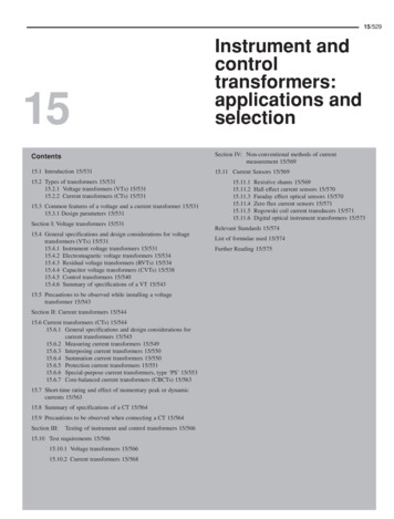
Transcription
Doble Testing Voltage (Potential)Transformers and Metering UnitsGary HeustonDoble Engineering Company
PROPRIETARY INFORMATIONDoble Engineering Company (“Doble ”), has full title, right and interest to allsubject matter contained in this presentation (“Proprietary Information”)regardless of the medium. You have been provided a copy of this ProprietaryInformation for private reference purposes only. Doble’s delivery to you ofDoble Proprietary Information does not constitute in any way whatsoever alicense of any kind or vests any interest in Doble’s Proprietary Information(other than private reference use), including, without limitation, the rights tocopy, disseminate, distribute, transmit, display or perform in public (or to thirdparties), reproduce, edit, translate or reformat. You, as recipient, acknowledgeand agree to these terms by your first viewing of this Proprietary Information.You further acknowledge and agree that Doble shall not have an adequateremedy at law in the event of your breach of the conditions hereunder, thatDoble will suffer irreparable damage and injury if you breach any of the conditions stated above, and that such breach occurs, Doble , in addition toany other rights and remedies available herein or otherwise, shall be entitled toseek an injunction to be issued by a tribunal of competent jurisdiction restrictingthe recipient from committing or continuing any breach of these conditions.2April 26, 2007 2007 Doble Engineering Company -74th Annual International Doble Client ConferenceAll Rights Reserved
Voltage Transformers3April 26, 2007 2007 Doble Engineering Company -74th Annual International Doble Client ConferenceAll Rights Reserved
VoltageTransformers4April 26, 2007 2007 Doble Engineering Company -74th Annual International Doble Client ConferenceAll Rights Reserved
Agenda Terminology Voltage transformer tests Power factor test- applicable policies- procedures- analysis of results- diagnostic tests5April 26, 2007 2007 Doble Engineering Company -74th Annual International Doble Client ConferenceAll Rights Reserved
Agenda Case studies- 1: typical DTA screens- 2: voltage transformer in satisfactory condition- 3: voltage transformers in satisfactory condition- 4: affect of winding inductance6April 26, 2007 2007 Doble Engineering Company -74th Annual International Doble Client ConferenceAll Rights Reserved
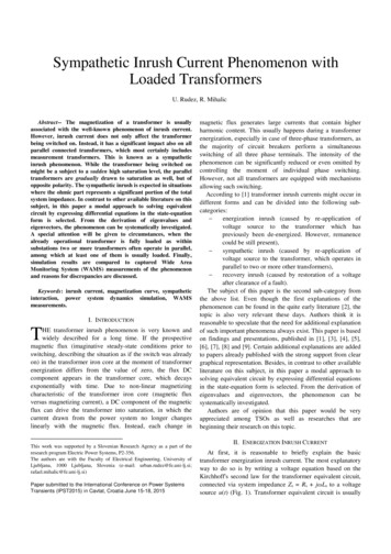
Design Types 1-bushing, line-to-neutral voltage transformers- conventional- cascade- inaccessible neutral terminal 2-bushing, line-to-line voltage transformers7April 26, 2007 2007 Doble Engineering Company -74th Annual International Doble Client ConferenceAll Rights Reserved
Design Types8April 26, 2007 2007 Doble Engineering Company -74th Annual International Doble Client ConferenceAll Rights Reserved
Design Types9April 26, 2007 2007 Doble Engineering Company -74th Annual International Doble Client ConferenceAll Rights Reserved
Design Types10April 26, 2007 2007 Doble Engineering Company -74th Annual International Doble Client ConferenceAll Rights Reserved
Design Types11April 26, 2007 2007 Doble Engineering Company -74th Annual International Doble Client ConferenceAll Rights Reserved
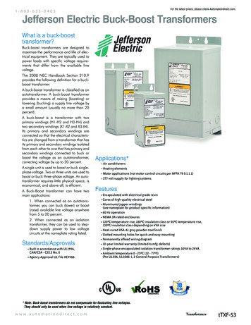
Dielectric Circuit12April 26, 2007 2007 Doble Engineering Company -74th Annual International Doble Client ConferenceAll Rights Reserved
Diel. Circuit with Interwinding Shield13April 26, 2007 2007 Doble Engineering Company -74th Annual International Doble Client ConferenceAll Rights Reserved
Terminology CP: insulation between primary (high-voltage)conductor and grounded core and tank (bushings,winding insulation, structural insulating members andinsulating fluid or material) CPS: insulation between primary- and secondaryconductors (winding insulation, barriers and insulatingor material) CS: insulation between secondary (low-voltage)conductors and grounded core and tank (bushings andterminal board, winding insulation, structural insulatingmembers and oil)14April 26, 2007 2007 Doble Engineering Company -74th Annual International Doble Client ConferenceAll Rights Reserved
Terminology H2: designation of second terminal of primary winding,regardless of its design. In earlier years, H0 wasdesignation of neutral terminal of line-to-neutralvoltage transformer.Connection to H2 terminal must be restored beforeenergizing this apparatus at operating voltage. Line-to-neutral (L-N) voltage rating: equals systemvoltage rating divided by 1.73.15April 26, 2007 2007 Doble Engineering Company -74th Annual International Doble Client ConferenceAll Rights Reserved
Modern Dry-Type Insulating Materials Butyl rubbers Cycloaliphatic epoxies Aromatic polyurethanes elastomers Hydrophobic cycloaliphatic epoxies16April 26, 2007 2007 Doble Engineering Company -74th Annual International Doble Client ConferenceAll Rights Reserved
Voltage Transformer TestsRoutinely includes these measurements: Power factor and capacitance Excitation current Doble ratio and polarity Infra-redsensitive to hot-spots17April 26, 2007 2007 Doble Engineering Company -74th Annual International Doble Client ConferenceAll Rights Reserved
Voltage Transformer TestsMay also include these measurements: Insulation resistance and polarization index (IR10/IR1)sensitive to contamination and deterioration Winding resistancesensitive to quality of connections and continuity ofconductors18April 26, 2007 2007 Doble Engineering Company -74th Annual International Doble Client ConferenceAll Rights Reserved
Voltage Transformer Tests Insulating fluid tests- mineral oil physical, chemical and electrical properties dissolved gases and metals- SF6 gas moisture and purity acidity and arc by-products19April 26, 2007 2007 Doble Engineering Company -74th Annual International Doble Client ConferenceAll Rights Reserved
Power Factor TestRoutine procedure varies with the design type, type ofinsulation and accessible neutral terminal: 1-bushing, line-to-neutral voltage transformer- liquid-filled and gas-filled conventional cascade- dry-type insulated conventional unaccessible neutral terminal20April 26, 2007 2007 Doble Engineering Company -74th Annual International Doble Client ConferenceAll Rights Reserved
Power Factor Test 2-bushing, line-to-line voltage transformer- liquid-filled- dry-type insulated21April 26, 2007 2007 Doble Engineering Company -74th Annual International Doble Client ConferenceAll Rights Reserved
Test PoliciesNecessary to address specific aspects of testing, toinclude: Applied test voltage »test dry-type insulated voltage transformers at 2voltages22April 26, 2007 2007 Doble Engineering Company -74th Annual International Doble Client ConferenceAll Rights Reserved
Applied Test VoltageLiquid-Filled, 2-Bushing, Line-to-Line Voltage TransformersSystem kV Rating15 and higherTest Voltage, kV10Below 15 kV, test at L-N voltage, to the nearest 500 Volts. Line-toneutral (L-N) voltage is system voltage divided by 1.73. Do notexceed 125 % L-N voltage rating.System kV Rating13.8 and 14.413.212.47117.2 to 8.74 to 52.423April 26, 2007Test Voltage, kV87.57.06.542.52 2007 Doble Engineering Company -74th Annual International Doble Client ConferenceAll Rights Reserved
Applied Test VoltageLiquid-Filled and Gas-Filled, 1-Bushing, Line-to-Neutral VoltageTransformersH2 Neutral TerminalSystem kV Rating92 and higherBelow 92Test Voltage, kV52Overall test performed at H2 neutral terminal test voltage.H1 Line TerminalSystem kV Rating15 and higherTest Voltage, kV10Below 15 kV, refer to test voltage applied to line-to-line voltagetransformers.24April 26, 2007 2007 Doble Engineering Company -74th Annual International Doble Client ConferenceAll Rights Reserved
Applied Test VoltageDry-Type Insulated, 2-Bushing, Line-to-Line Voltage TransformersSystem kV Rating15 and higherTest Voltage, kV2 and 10Below 15 kV, test at 2 kV and L-N voltage, to the nearest 500 Volts.Line-to-neutral (L-N) voltage is system voltage divided by 1.73. Donot exceed 125 % L-N voltage rating.System kV Rating13.8 and 14.413.212.47117.2 to 8.74 to 52.425April 26, 2007Test Voltage, kV2 and 82 and 7.52 and 7.02 and 6.52 and 42.52 2007 Doble Engineering Company -74th Annual International Doble Client ConferenceAll Rights Reserved
Applied Test VoltageDry-Type Insulated, 1-Bushing, Line-to-Neutral VoltageTransformersH2 Neutral TerminalSystem kV RatingBelow 92Test Voltage, kV2Overall test performed at H2 neutral terminal test voltage.H1 Line TerminalSystem kV Rating15 and higherTest Voltage, kV2 and 10Below 15 kV, refer to test voltage applied to line-to-line voltagetransformers.26April 26, 2007 2007 Doble Engineering Company -74th Annual International Doble Client ConferenceAll Rights Reserved
Test Policies Winding inductance effectconnect terminals of primary winding together forOverall Test Disposition of secondary windings- isolate secondary windings- ground one terminal of each secondary winding27April 26, 2007 2007 Doble Engineering Company -74th Annual International Doble Client ConferenceAll Rights Reserved
Test Policies Temperature correction »- correct power factor for liquid-filled voltagetransformers with ambient temperature- power factor for SF6 and dry-type insulated voltagetransformers not correctedM4000 instrument measures ambient temperature andrelative humidity automatically28April 26, 2007 2007 Doble Engineering Company -74th Annual International Doble Client ConferenceAll Rights Reserved
Temperature CorrectionTABLE OF MULTIPLIERS FOR USE IN CONVERTING POWER FACTORAT TEST TEMPERATURES TO POWER FACTORS AT 20 CTestTemperature C 29April 26, 2007Oil-Filled VTs, CTs and MUsModernrated 220 kV and aboveAll 20.540.490.450.41- 2007 Doble Engineering Company -74th Annual International Doble Client ConferenceAll Rights Reserved
Test ProcedureRoutine procedure for voltage transformers, withaccessible neutral terminalHVTest Cable1H1, H22H13H24H15H2LV LeadsRedBlueH2H1H2H1-Test ModeGST Ground Red BlueGST Guard Red Ground BlueGST Guard Red Ground BlueUST Measure Red Ground BlueUST Measure Red Ground BlueTests 1, 2 and 3: power factor testsTests 4 and 5: excitation current tests30April 26, 2007 2007 Doble Engineering Company -74th Annual International Doble Client ConferenceAll Rights Reserved
Overall TestHVCableH1,H231April 26, 2007LV LeadsRedBlue-Test ModeGST Ground Red Blue 2007 Doble Engineering Company -74th Annual International Doble Client ConferenceAll Rights Reserved
Overall Test Dielectric CircuitMeasures CP CPS32April 26, 2007 2007 Doble Engineering Company -74th Annual International Doble Client ConferenceAll Rights Reserved
Cross-Check 1 TestHVCableH133April 26, 2007LV LeadsRedBlueH2-Test ModeGST Guard Red Ground Blue 2007 Doble Engineering Company -74th Annual International Doble Client ConferenceAll Rights Reserved
Cross-Check 1 Dielectric CircuitMeasures CP1 CPS1 (isolates H1 terminal insulation)34April 26, 2007 2007 Doble Engineering Company -74th Annual International Doble Client ConferenceAll Rights Reserved
Cross-Check 2 TestHVCableH235April 26, 2007LV LeadsRedBlueH1-Test ModeGST Guard Red Ground Blue 2007 Doble Engineering Company -74th Annual International Doble Client ConferenceAll Rights Reserved
Cross-Check 2 Dielectric CircuitMeasures CP2 CPS2 (isolates H2 terminal insulation)36April 26, 2007 2007 Doble Engineering Company -74th Annual International Doble Client ConferenceAll Rights Reserved
Case 1: DTA Nameplate Screen37April 26, 2007 2007 Doble Engineering Company -74th Annual International Doble Client ConferenceAll Rights Reserved
Case 1: DTA Overall Test Screen38April 26, 2007 2007 Doble Engineering Company -74th Annual International Doble Client ConferenceAll Rights Reserved
Overall Test AnalysisPower factor compared with: Initial test- purchase specification- manufacturer’s specification- similar voltage transformers- Doble’s typical results and database Later tests compared with initial test valueQuestionable results in later tests- manufacturer’s specification- Doble’s typical results and database39April 26, 2007 2007 Doble Engineering Company -74th Annual International Doble Client ConferenceAll Rights Reserved
Overall Test AnalysisGeneral guidelines: Power factor »- modern oil-impregnated paper-insulated voltagetransformersless than 1.0 % at 20 C- SF6 insulated voltage transformersless than 1.0 % at test temperature- voltage transformers with other insulationsrefer to Doble’s typical results and database40April 26, 2007 2007 Doble Engineering Company -74th Annual International Doble Client ConferenceAll Rights Reserved
Tabulated Overall Test ResultsMfr.GE41April 26, 2007Percent Power Factor at 20 C or Test TemperatureRatedNo. of 0.00 0.30 0.50 0.70 0.90 1.10 2.00 3.00 4.00 5.00System*UnitstotototototototototoTypekVDesign Tested 0.29 0.49 0.69 0.89 1.09 1.99 2.99 3.99 4.99 5.99EW-650138O145832 42 32 11 146-750161O3139766-900230O95221 43 1478-1050345O2345554-1175345O4410912 112-1300345O582523 4510 26 17 20 36 1738.4R61817 17 115312R206616114.4R182829 22 29 39 24 179518R615JVS-15025R12717 18 24 37 27-20034.5R5516 208384-25046R16376-35069R12130 62 19811JVT-15025R692914 18 2042-20034.5R175547 60 21 16 1691-25046R45619 12431-35069R508259611 2007 Doble Engineering Company -74th Annual International Doble Client ConferenceAll Rights Reserved
Cross-Check Analysis Power factors generally similar to Overall power factor. Assist in evaluating questionable Overall test results.Isolate localized condition to one end of primarywinding versus a general condition. Sum of two cross-check currents should approximateoverall current. Same is true for Watts (andcapacitance). Unsatisfactory comparison couldindicate an open circuit or high resistance connection. Line-to-line voltage transformers produce similarcurrent, Watts and capacitance values. Line-to-neutralvoltage transformers produce dissimilar current, Wattsand capacitance values.42April 26, 2007 2007 Doble Engineering Company -74th Annual International Doble Client ConferenceAll Rights Reserved
Case 2: Typical ResultsResults measured for oil-filled line-to-neutral potentialtransformerTestTestDescriptionEquiv. 10 kV% Power FactorCorr.Cap.kVI 500.501.00556.502Cross-Check 1100.4000.0200.500.501.00106.003Cross-Check k Sum556.50Sum of Cross-Check currents approximate Overallcurrent. Same is true for Watts (and capacitance).Line-to-neutral potential transformers measure dissimilarcurrent, Watts and capacitance values.43April 26, 2007 2007 Doble Engineering Company -74th Annual International Doble Client ConferenceAll Rights Reserved
Overall Test AnalysisCapacitance compared with: Initial test- similar voltage transformers- Doble’s database Later tests compared with initial test value (% diff.)44April 26, 2007- goodless than 5 %- deterioratedfrom 5 % to less than 10 %- investigate10 % and higher 2007 Doble Engineering Company -74th Annual International Doble Client ConferenceAll Rights Reserved
Excitation Current 1 TestHVCableH145April 26, 2007LV LeadsRedBlueH2-Test ModeUST Measure Red Ground Blue 2007 Doble Engineering Company -74th Annual International Doble Client ConferenceAll Rights Reserved
Excitation Current 1 Diel. CircuitChecks turn insulation integrity and continuity of primaryconductor46April 26, 2007 2007 Doble Engineering Company -74th Annual International Doble Client ConferenceAll Rights Reserved
Excitation Current 2 TestHVCableH247April 26, 2007LV LeadsRedBlueH1-Test ModeUST Measure Red Ground Blue 2007 Doble Engineering Company -74th Annual International Doble Client ConferenceAll Rights Reserved
Excitation Current 2 Diel. CircuitChecks turn insulation integrity and continuity of primaryconductor in reverse direction48April 26, 2007 2007 Doble Engineering Company -74th Annual International Doble Client ConferenceAll Rights Reserved
Excitation Current Analysis Initial test compared with:- current in reverse direction (within 10 %)requires normal and reverse tests at same voltage- similar metering units- Doble’s database Later tests compared with initial test values49April 26, 2007 2007 Doble Engineering Company -74th Annual International Doble Client ConferenceAll Rights Reserved
Diagnostic TestsPerform when questionable results are measured forroutine tests. Questionable results include high,abnormally low or negative power factor. Also, high orlow capacitance.Diagnostic tests include: Hot-Collar testdetects localized condition and monitors surfacelosses Test at several voltages (power factor tip-up)detects voltage sensitive condition, e.g. carbonizedpath50April 26, 2007 2007 Doble Engineering Company -74th Annual International Doble Client ConferenceAll Rights Reserved
Diagnostic Tests Primary to secondary winding tests »checks interwinding insulation Insulating fluid tests- mineral oil physical, chemical and electrical properties dissolved gases and metals- SF6 gas moisture and purity acidity and arc by-productsDon’t Open a Voltage Transformer with NegativePressure51April 26, 2007 2007 Doble Engineering Company -74th Annual International Doble Client ConferenceAll Rights Reserved
Diagnostic TestsPerform when questionable results are measured forroutine tests.Isolate all secondary windings from ground for thesediagnostic tests.HVLV LeadsTestCableRedBlueTest ModeMeasure6H1,H2X3*Y3UST Measure Red Ground BlueCPX7H1,H2Y3*X3UST Measure Red Ground BlueCPY8H1H2**X3,Y3GST Guard Red BlueCP19H2H1**X3,Y3GST Guard Red BlueCP2*Some voltage transformers have less or more secondary windings.Test each primary to secondary path separately.**Connect any one terminal of each secondary winding to guard.52April 26, 2007 2007 Doble Engineering Company -74th Annual International Doble Client ConferenceAll Rights Reserved
SummaryRoutine procedure for voltage transformers, withaccessible neutral terminalHVTest Cable1H1, H22H13H24H15H2LV LeadsRedBlueH2H1H2H1-Test ModeGST Ground Red BlueGST Guard Red Ground BlueGST Guard Red Ground BlueUST Measure Red Ground BlueUST Measure Red Ground BlueTests 1, 2 and 3: power factor testsTests 4 and 5: excitation current tests53April 26, 2007 2007 Doble Engineering Company -74th Annual International Doble Client ConferenceAll Rights Reserved
Safety CommentsBefore placing a voltage transformer in operation: One terminal of each secondary winding must alwaysbe grounded, either directly or through aninterconnection. The electrostatic voltage coupled to asecondary winding may reach a dangerous anddestructive value unless it’s connected to ground. The reduced insulation neutral terminal of a gradedinsulation line-to-neutral voltage transformer mustalways be solidly grounded. Never short-circuit a voltage transformer secondarywinding. This will produce very high current in thissecondary winding and cause it to overheat and fail.54April 26, 2007 2007 Doble Engineering Company -74th Annual International Doble Client ConferenceAll Rights Reserved
DTA Data Entry Requirements File savinglocation and serial number File merginglocation, serial number and *special identification*special identification field can be blank but it must beblank in both files Temperature correctionkV rating, year of manufacture and ambienttemperature Analysis of resultsmanufacturer, type, insulation type and kV rating55April 26, 2007 2007 Doble Engineering Company -74th Annual International Doble Client ConferenceAll Rights Reserved
DTA Data Entry Requirements Total functionalitylocation, *special identification, manufacturer, serialnumber, year of manufacturer, type, insulation type, kVrating and ambient temperature56April 26, 2007 2007 Doble Engineering Company -74th Annual International Doble Client ConferenceAll Rights Reserved
Case 3: Typical ResultsTestDescription1 Overall2 Cross-Check 13 Cross-Check 2Cross-Check Sum4 Excitation Current 15 Excitation Current 21 Overall2 Cross-Check 13 Cross-Check 2Cross-Check Sum4 Excitation Current 15 Excitation Current 21 Overall2 Cross-Check 13 Cross-Check 2Cross-Check Sum4 Excitation Current 15 Excitation Current 257April 26, 2007TestkV510555510555510555Equiv. 10 kVI (mA) Watts3.775 0.1341.281 0.0292.429 0.1053.710 0.1340.1970.2053.823 0.1331.324 0.0312.426 0.1023.750 0.1330.2050.2053.724 0.1271.275 0.0282.389 0.0993.664 0.1270.2010.205% Power Factor Corr.Cap.Meas. Corr. Factor(pF)0.350.391.11 1,000.380.230.261.11 339.471.11 240.461.111.111.11986.86337.88633.09970.97 2007 Doble Engineering Company -74th Annual International Doble Client ConferenceAll Rights Reserved
Case 4: Winding Inductance AffectResults measured without and with primary winding terminalsconnected together for Overall test.TestDescription1 Overall2 Cross-Check 13 Cross-Check 2Cross-Check Sum123OverallCross-Check 1Cross-Check 2Cross-Check SumTestkV51055105Equiv. 10 kVI (mA) Watts1.323 1.7441.275 0.0292.393 0.1013.668 0.1303.7751.2812.4293.7100.1340.0290.1050.134% Power Factor Corr.Cap.Meas. Corr. Factor(pF)13.18 14.63 1.11 350.600.230.261.11 337.880.420.471.11 000.38339.47643.69983.16Connecting H1 and H2 terminals together for Overall test eliminateswinding inductance effect.Trench 115 kV oil-filled line-to-neutral potential transformer, Catalog No. UT5-550-11558April 26, 2007 2007 Doble Engineering Company -74th Annual International Doble Client ConferenceAll Rights Reserved
Inaccessible Neutral TerminalRoutine procedure for voltage transformers withinaccessible neutral terminalHVLV LeadsTestCableRedBlueTest Mode1H1X3,Y3-UST Measure Red Ground Blue2H1X3,Y3-GST Guard Red Ground BlueTest 1: power factor testTest 2: excitation current test59April 26, 2007 2007 Doble Engineering Company -74th Annual International Doble Client ConferenceAll Rights Reserved
Power Factor TestHVCableH160April 26, 2007LV LeadsRedBlueX3,Y3-Test ModeUST Measure Red Ground Blue 2007 Doble Engineering Company -74th Annual International Doble Client ConferenceAll Rights Reserved
Excitation Current TestHVCableH161April 26, 2007LV LeadsRedBlueX3,Y3-Test ModeGST Guard Red Ground Blue 2007 Doble Engineering Company -74th Annual International Doble Client ConferenceAll Rights Reserved
Single-Phase Metering Units62April 26, 2007 2007 Doble Engineering Company -74th Annual International Doble Client ConferenceAll Rights Reserved
Single-Phase Metering UnitIncludes current and voltage elements63April 26, 2007 2007 Doble Engineering Company -74th Annual International Doble Client ConferenceAll Rights Reserved
Test ProcedureRoutine procedure for single-phase metering unitsHVTestCable1H1, H22H13LV LeadsRedBlueTest Mode-GST Ground Red BlueH2-GST Guard Red Ground BlueH2H1-GST Guard Red Ground Blue4H1H2-UST Measure Red Ground Blue5H2H1-UST Measure Red Ground BlueTests 1, 2 and 3: power factor testsTests 4 and 5: excitation current tests64April 26, 2007 2007 Doble Engineering Company -74th Annual International Doble Client ConferenceAll Rights Reserved
Test PoliciesNecessary to address specific aspects of testing, toinclude: Applied test voltage »same voltage as for potential transformers65April 26, 2007 2007 Doble Engineering Company -74th Annual International Doble Client ConferenceAll Rights Reserved
Applied Test VoltageLine-to-Line Metering UnitsSystem kV Rating15 and higherTest Voltage, kV10Below 15 kV, test at L-N voltage, to the nearest 500Volts. Line-to-neutral (L-N) voltage is system voltagedivided by 1.73. Do not exceed 125 % L-N voltagerating.66April 26, 2007 2007 Doble Engineering Company -74th Annual International Doble Client ConferenceAll Rights Reserved
Applied Test VoltageLiquid-Filled and Gas-Filled, Line-to-Neutral Metering UnitsNeutral TerminalSystem kV Rating92 and higherbelow 92Test Voltage, kV52Line TerminalsSystem kV Rating15 and higherTest Voltage, kV10Below 15 kV, test at L-N voltage, to the nearest 500 Volts. Line-toneutral (L-N) voltage is system voltage divided by 1.73. Do notexceed 125 % L-N voltage rating.67April 26, 2007 2007 Doble Engineering Company -74th Annual International Doble Client ConferenceAll Rights Reserved
Test Policies Winding inductance effectconnect terminals of current and potential primarywindings together for Overall Test Disposition of secondary windings- isolate secondary windings- ground one terminal of each secondary winding Temperature correction »correct power factor with ambient temperatureM4000 instrument measures ambient temperature andrelative humidity automatically68April 26, 2007 2007 Doble Engineering Company -74th Annual International Doble Client ConferenceAll Rights Reserved
Temperature CorrectionTABLE OF MULTIPLIERS FOR USE IN CONVERTING POWER FACTORAT TEST TEMPERATURES TO POWER FACTORS AT 20 CTestTemperature C 69April 26, 2007Oil-Filled VTs, CTs and MUsModernrated 220 kV and aboveAll 20.540.490.450.41- 2007 Doble Engineering Company -74th Annual International Doble Client ConferenceAll Rights Reserved
Overall TestHVCableH1,H270April 26, 2007LV LeadsRedBlue-Test ModeGST Ground Red Blue 2007 Doble Engineering Company -74th Annual International Doble Client ConferenceAll Rights Reserved
Overall Test Dielectric CircuitMeasures CP CPS71April 26, 2007 2007 Doble Engineering Company -74th Annual International Doble Client ConferenceAll Rights Reserved
Cross-Check 1 TestHVCableH172April 26, 2007LV LeadsRedBlueH2-Test ModeGST Guard Red Ground Blue 2007 Doble Engineering Company -74th Annual International Doble Client ConferenceAll Rights Reserved
Cross-Check 2 TestHVCableH273April 26, 2007LV LeadsRedBlueH1-Test ModeGST Guard Red Ground Blue 2007 Doble Engineering Company -74th Annual International Doble Client ConferenceAll Rights Reserved
Excitation Current 1 TestHVCableH174April 26, 2007LV LeadsRedBlueH2-Test ModeUST Measure Red Ground Blue 2007 Doble Engineering Company -74th Annual International Doble Client ConferenceAll Rights Reserved
Excitation Current 2 TestHVCableH275April 26, 2007LV LeadsRedBlueH1-Test ModeUST Measure Red Ground Blue 2007 Doble Engineering Company -74th Annual International Doble Client ConferenceAll Rights Reserved
Overall Test AnalysisPower factor compared with: Initial test- purchase specification- manufacturer’s specification- similar metering units- Doble’s typical results and database Later tests compared with initial test valueQuestionable results in later tests- manufacturer’s specification- Doble’s typical results and database76April 26, 2007 2007 Doble Engineering Company -74th Annual International Doble Client ConferenceAll Rights Reserved
Overall Test AnalysisGeneral guidelines: Power factor »- modern oil-impregnated paper-insulated meteringunitsless than 1.0 % at 20 C- SF6 insulated metering unitsless than 1.0 % at test temperature- older metering unitsrefer to Doble’s database and typical results77April 26, 2007 2007 Doble Engineering Company -74th Annual International Doble Client ConferenceAll Rights Reserved
Tabulated Overall Test ResultsMfr.A-CTypePCWGEKFEWest78April 26, 2007MP-8.7-15-25-34.5-46-69-115-138Percent Power Factor at 20 C or Test TemperatureRatedNo. of 0.00 0.30 0.50 0.70 0.90 1.10 2.00 3.00 4.00 5.00System*UnitstotototototototototokVDesign Tested 0.29 0.49 0.69 0.89 1.09 1.99 2.99 3.99 4.99 12919111216121431319118141591423354362 2007 Doble Engineering Company -74th Annual International Doble Client ConferenceAll Rights Reserved52212
Cross-Check Analysis Power factors generally similar to Overall power factor. Assist in evaluating questionable Overall test results.Isolate localized condition to one end of primarywinding versus a general condition. Sum of two cross-check currents should approximateoverall current. Same is true for Watts (andcapacitance). Unsatisfactory comparison couldindicate an open circuit or high resistance connection. Line-to-neutral metering units produce dissimilarcurrent, Watts and capacitance values.79April 26, 2007 2007 Doble Engineering Company -74th Annual International Doble Client ConferenceAll Rights Reserved
Overall Test AnalysisCapacitance compared with: Initial test- similar metering units- Doble’s database Later tests compared with initial test value (% diff.)80April 26, 2007- goodless than 5 %- deterioratedfrom 5 % to less than 10 %- investigate10 % and higher 2007 Doble Engineering Company -74th Annual International Doble Client ConferenceAll Rights Reserved
Excitation Current Analysis Initial test, compared with:- current in reverse direction (within 10 %)requires normal and reverse tests at same voltage- similar metering units- Doble’s database Later tests compared with initial test values81April 26, 2007 2007 Doble Engineering Company -74th Annual International Doble Client ConferenceAll Rights Reserved
Diagnostic TestsPerform when questionable results are measured forroutine tests. Questionable results include high,abnormally low or negative power factor. Also, low orhigh capac
Doble Testing Voltage (Potential) Transformers and Metering Units Gary Heuston Doble Engineering Company. 2 April 26, 2007 . Voltage transformer tests Power factor test - applicable policies - procedures - analys