Transcription
Overshadow PLC to Detect RemoteControl-Logic Injection AttacksHyunguk Yoo1 , Sushma Kalle1 , Jared Smith2 , and Irfan Ahmed1,31University of New Orleans, New Orleans LA 70148{hyoo1,skalle1}@uno.edu2Oak Ridge National Laboratory, Oak Ridge, TN 37830smithjm@ornl.gov3Virginia Commonwealth University, Richmond VA 23221iahmed3@vcu.eduAbstract. Programmable logic controllers (PLCs) in industrial controlsystems (ICS) are vulnerable to remote control logic injection attacks.Attackers target the control logic of a PLC to manipulate the behavior ofa physical process such as nuclear plants, power grids, and gas pipelines.Control logic attacks have been studied extensively in the literature, including hiding the transfer of a control logic over the network from bothpacket header-based signatures, and deep packet inspection. For instance,these attacks transfer a control logic code as data, into small fragments(one-byte per packet), that are further padded with noise data. To detectcontrol logic in ICS network traffic, this paper presents Shade, a novelshadow memory technique that observes the network traffic to maintain alocal copy of the current state of a PLC memory. To analyze the memorycontents, Shade employs a classification algorithm with 42 unique features categorized into five types at different semantic levels of a controllogic code, such as number of rungs, number of consecutive decompiledinstructions, and n-grams. We then evaluate Shade against control logicinjection attacks on two PLCs, Modicon M221 and MicroLogix 1400 fromtwo ICS vendors, Schneider electric and Allen-Bradley, respectively. Theevaluation results show that Shade can detect an attack instance (i.e.,identifying at least one attack packet during the transfer of a maliciouscontrol logic) accurately without any false alarms.Keywords: Control Logic · PLC · SCADA · Industrial Control System.1IntroductionIndustrial Control Systems (ICS) actively control and monitor physical processes in critical infrastructure industries such as wastewater treatment plants,gas pipelines, and electrical power grids. Since the discovery of Stuxnet in 2010,an unseen nation-state malware that sabotaged Iran’s nuclear facilities, thenumber of ICS vulnerabilities reported each year has been dramatically increased [18], and sophisticated attacks targeting critical infrastructure continueto occur [13, 14, 17, 20]. Designed to be isolated from the outside world, the
2Yoo et al.security of ICS environments was not a priority. However, these devices are increasingly becoming connected to corporate networks and the broader Internetfor economic gain, more fluid business processes, and compatibility with traditional digital IT infrastructure [10, 22]. Unfortunately, their connectivity exposesvulnerabilities and unrestricted access by remote and insider attacks.Within the ICS domain, Programmable Logic Controllers (PLCs) directlycontrol a physical process located at a field site. Occurring in many ICS environments [19], PLCs are controlled by remote control center systems such as ahuman-machine interface (HMI) and engineering workstations via ICS-specificnetwork protocols, such as Modbus, and DNP3 [7]. A PLC is equipped with acontrol logic that defines how the PLC should control a physical process.Acting via channels exposed by the increasingly large threat surface of ICSnetworks and devices, attackers can target the control logic of a PLC to manipulate the behavior of a physical process. For instance, Stuxnet infects thecontrol logic of a Siemens S7-300 PLC to modify the motor speed of centrifugesperiodically from 1,410 Hz to 2 Hz to 1,064 Hz repeatedly, resulting in devicefailure. In most cases, the control logic of a PLC can be updated through thenetwork using modern, yet typically not encrypted PLC communication protocols. Exploiting this feature, various classes of remote control logic injectionattacks have been studied in the past, such as Stuxnet [8], Denial of Engineering Operations (DEO) attacks [24], and Fragmentation and Noise Padding [27].Upon detection, a typical response may include blocking any transfer of controllogic over the targeted network. For instance, Stuxnet compromises the STEP 7engineering software [8] in a control center to communicate with a target PLCin a field site. Next, the malware transfers a malicious control logic program tothe PLC. Notably, this attack can be prevented if ICS operators prevent thetransfer of control logic over the network.Recently, Yoo and Ahmed [27] presented two stealthy control logic injectionattacks, referred to as Data Execution, and Fragmentation and Noise Paddingto demonstrate that an attacker can subvert both packet-header signatures andpayload inspection to transfer control logic to a PLC successfully. In the DataExecution attack, an attacker deceives packet header inspection by transferringcontrol logic to data blocks of a target PLC and then, modifies the PLC’s systemcontrol flow to execute the logic located in data blocks. Packet-header signaturesdo not prevent the data blocks because they contain sensor measurement values and actuator state, which are normally sent to the human-machine interfaceat the control center. In the Fragmentation and Noise Padding attack, an attacker sends a control logic to a PLC in small fragments (typically one byteper packet) and further adds a large padding of noise to evade traditional deeppacket inspection.These attacks give adversaries a significant advantage over operators relying on existing modern protections against network-based attacks, which utilizestealth-mechanisms. To that end, this paper presents a first-of-its-kind system,Shade to detect control logic in an ICS network traffic when an attacker employsboth stealthy Data Execution, and Fragmentation and Noise Padding attacks to
Overshadow PLC to Detect Remote Control-Logic Injection Attacks3compromise critical infrastructure networks. Shade observes ICS network traffic to maintain a local (shadow) copy of a PLC’s memory layout using read andwrite messages from and to the PLC. Our system scans the shadow memory as anensemble of supervised learning algorithms with 42 custom, domain-relevant features of control logic code categorized into five types. These types lie at differentlevels of semantics extracted from the PLC control logic code: 1) decompilation,2) rung, 3) opcode identification, 4) n-gram, and 5) entropy.We implement the attacks on two different vendors’ PLCs, Allen Bradley’sMicroLogix 1400 and Schneider Electric’s Modicon M221. Note that these PLCsare originally utilized by Yoo and Ahmed to demonstrate the attacks [27], andwe use them to recreate the attacks to evaluate the accuracy of Shade. Ourevaluation results show that while the traditional payload inspection fails todetect these attacks, Shade can detect the transfer of all control logic programsaccurately without any false alarms. Furthermore, Shade’s performance overheadlies at 2%, a necessary trait for ease of deployment into real-world ICS networks.Contributions. Our contributions can be summarized as follows:– We validate two recent stealthy control-logic injection attacks that can subvert both protocol header signatures and deep packet inspection.– We present Shade, which is a novel shadow memory approach to detectcontrol logic code in ICS network traffic when the stealthy control logicattacks are employed.– We study different types of the features on control logic code at differentsemantic levels of a control logic and identify a best set of feature to achieveoptimal results, i.e., accurate detection of the transfer of control logic instances in an ICS network traffic without any false positives.– We evaluate Shade on real-world PLCs used in industrial settings.– We release our datasets and the source code of Shade1 .Roadmap. We have organized the rest of the paper as follows: Section 2 provides the background. Section 3 presents the shadow memory-based control logicdetection technique, followed by its implementation and evaluation results in Section 4 and Section 6 respectively. Section 7 covers the related work, followed bythe conclusion in Section 8.2Background: Control Logic Injection AttacksControl logic is a program which is executed repeatedly in a PLC. It is programmed and compiled using engineering software provided by PLC vendors.There are five PLC programming languages defined by IEC 61131-3 [11]: ladderlogic, instruction list, functional block diagram, structured text, and sequentialflow chart. A PLC is usually equipped with communication interfaces such asRS-232 serial ports, Ethernet, and USB to communicate with the engineeringsoftware so that control logic can be downloaded to or uploaded from a PLC.In general, a control logic can be divided into four different blocks whentransferred to or from a PLC: the configuration block, code block, data block,and information block. The configuration block contains information on the other1https://gitlab.com/hyunguk/plcdpi/
4Yoo et al.blocks (e.g., the address and size of the blocks) and other configuration settingsfor the PLC (e.g., IP address of the PLC). The compiled code-block controls logiccode running in the PLC. The data block maintains the variables (e.g, input,output, timer, etc.) used in the code block. Finally, engineering software usesthe information block to recover the original project file from the decompiledsource code when the control logic is uploaded to the engineering software.In a typical control logic injection attack [8, 24], an attacker downloads malicious control logic onto a target PLC by interfering with the normal PLCengineering operation of downloading/uploading control logic. Stuxnet [8], a representative example of this type of attack, infects Siemens SIMATIC STEP 7(engineering software) and downloads malicious control logic to target PLCs(Siemens S7-300) by utilizing the infected engineering software. The lack of authentication measures in the PLC communication protocols results in successfulexploitation. In our experience, control logic downloading/uploading operationsdo not support authentication or authentication is only supported in one direction, either download or upload.Recently, Yoo and Ahmed [27] presented two stealthy control logic injectionattacks, referred to as Data Execution, and Fragmentation and Noise Padding tohide the transfer of control logic over the network from packet-header signaturesand deep packet inspection. We now cover these attacks in detail.Data Execution Attack. The Data Execution Attack evades network intrusion detection systems (NIDS) that rely on signatures based on packet headerfields by transferring the compiled code of control logic to the data blocks of aPLC. The data blocks exchange sensor measurement values and states of PLCvariables (e.g., inputs, coil, timers, and counters). Since control center applications (e.g., HMI) may frequently read and write on those data, the NIDSsignatures must not raise an alarm for data blocks in the network traffic ofICS environments. Therefore, the attack evades the NIDS signatures by embedding attacker’s logic code in data blocks. After transferring the logic code toa PLC, the attack further modifies the pointer to the code block to executethe attacker’s logic located in data blocks. This code could contain instructionssimilar to Stuxnet, which would result in major ICS failures and costly repercussions. Most PLCs in the market do not enforce data execution prevention (DEP),thereby allowing the logic in data blocks to execute. However, this attack canbe subverted by payload-based anomaly detection.Fragmentation and Noise Padding Attack. This attack subverts payloadbased anomaly detection by appending a sequence of padding bytes (noise) incontrol logic packets while keeping the size of the attacker’s logic code in packetpayloads significantly small. The ICS protocol often have address or offset fieldsin their headers, which are utilized by the attack to make the PLC discard thenoise padding.In their study [27], they showed that both signature-based header inspectionand payload-based anomaly detection can be bypassed by an attack combiningthe two stealthy attacks, i.e., transferring attacker’s logic code in a data blockwhile fragmenting the code and appending a noise padding.
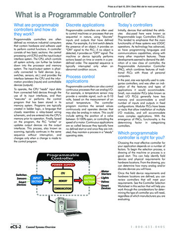
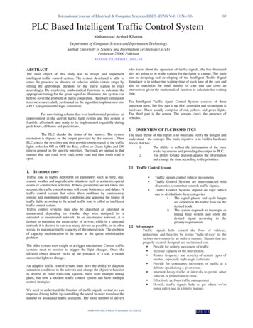
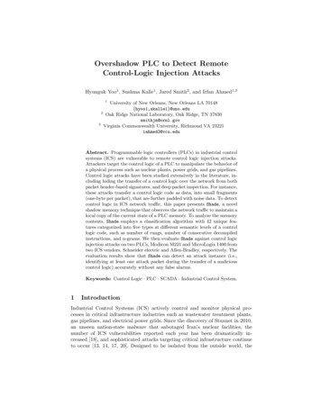
Overshadow PLC to Detect Remote Control-Logic Injection Attacks5PLC protocol headerWrite requestmessageShadowMemoryAddr: xlen: npayloadmirroredb b payloadx-bxx nx n bscan areaFig. 1. Shadow memory scanning33.1Shadow Memory-based Control Logic DetectionShade - a Shadow Memory ApproachGenerally, shadow memory refers to a technique to store information on memory(e.g., whether each byte of memory is safe to access), which is utilized in mostmemory debuggers [6, 9]. In this paper, however, we present shadow memory asa mirrored space of the protocol address space of a PLC. We define the protocoladdress space of a PLC as the range of space that can be addressed for payloaddata through a PLC protocol. For example, if the write request message formatof a PLC protocol has a fixed 2-byte address field that specifies the byte offsetof data to be written, the address space of the PLC protocol will be 64KB.The proposed approach referred to as Shade maintains shadow memory ofeach PLC and detects control logic code by scanning the shadow memory ratherthan the individual packet payloads. Briefly speaking, Shade works as follows:when a write request packet to a PLC is identified in an ICS network traffic,its payload data is reflected in the shadow memory. Shade uses packet-headervalues to map the data at a correct memory location of the shadow memoryand excludes any excess data (such as noise) that resides in a packet payloadbut is not written to the PLC memory. Note that attacker can exploit protocolspecifications to include noise data in a packet payload but does not write thenoise to PLC memory to avoid any risk of crashing the PLC. In Fragmentationand Noise Padding, attacker manipulates header values to filter noise data whenthe packet arrives at the PLC. After mapping a payload to shadow memory,Shade scans the shadow memory to determine whether or not the control logiccode resides in the memory. Even though each attack packet of the Fragmentationand Noise Padding attack contains a tiny size of code fragment with large noise,it will eventually composes a detectable size of code chunk in the shadow memory,thus making the proposed detection method effective.Figure 1 depicts the mirroring and scanning of shadow memory. When a writerequest packet is identified, its payload is mirrored to shadow memory accordingto the packet’s address and length fields. Then, we scan the surrounding spaceincluding the area where the payload is mirrored. We call the area scanned foreach write request packet the scan area. The range of the scan area is determinedby the payload size, the address of a write request packet, and the scan boundaryparameter b. With the address x and the payload length n, the lower bound of thescan area is defined by M AX(0, x b) and the upper bound is M IN (m, x n b),where m is the highest address of shadow memory.
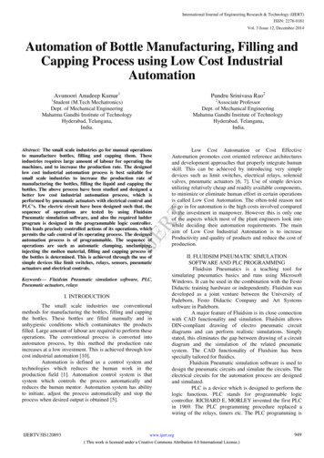
6Yoo et al.Instead of scanning the whole memory, we propose to scan a small chunkof relevant shadow memory which is updated recently. This approach has twoadvantages: 1) Avoid overhead, and 2) Reduce false alarms.Avoiding overhead. Scan of a small memory chunk avoids significant performance overhead. As we will show in Section 6, the overhead of shadow memoryscanning is 31.92% for the Schneider Electric’s M221 PLC with a boundaryparameter of 236 and 701 bytes of scan range in average. If we perform a fullscanning for the M221 PLC, of which the shadow memory size is around 64KB,the overhead will be unfeasible for a real-world deployment.Reduce false alarms. Worse, full-scanning more often produces false positives.If a non-code packet (e.g., a packet containing PLC variable data or configurationinformation) is misclassified as a code packet, all the following non-code packetswill be misclassified as well unless the mirrored payload data of the initiallymisclassified packet is removed from the shadow memory. However, clearing acertain area of shadow memory makes the shadow memory inconsistent with theactual state of a PLC, which could lead to failure of detecting attack packetscontaining fragmented code later.With partial-scanning, the scan boundary parameter b is a trade-off factor.Increasing b would raise the true positive rate (increase sensitivity) but also raisethe false positive rate and performance overhead, and vice-versa. Assume that nis the minimum size of the code fragment that can be detected by a classificationalgorithm C, and k is the maximum payload size, then n must be smaller thank if the classification algorithm C has high sensitivity for detecting logic code ina packet payload.With shadow memory, if a code chunk in the shadow memory is larger thanor equal to n, setting b with k ensures that the classification algorithm C candetect it. Let’s assume that (n 1) bytes of code in shadow memory from addressx to (x n 1), and one-byte of attacker’s code fragment is being written toshadow memory. If the one-byte code is written at the address (x 1) or (x n),then the size of code chunk will be n bytes which can be detected. Note that theattacker can write different parts of a code in a random sequence, which maydelay the detection. However, the consecutive code size will end up exceedingn-bytes of code chunk in the scan area and is detected by Shade.3.2 Feature Extraction with Different Semantic LevelsIn the training phase, Shade extracts 42 different features 1 from the scan areaof shadow memory, then it selects only the best features for training a classifier.Figure 2 highlights the different features with varying semantic levels studied inthis paper. N-gram or entropy does not require any syntax or semantic knowledgeof the underlying data. On the other hand, features such as the number of theidentified opcodes, the number of the rungs, and the number of successfullydecompiled bytes require knowledge about the format and semantics of the data.Decompilation of Control Logic Code. The feature #dec represents thelongest length of a byte sequence which is successfully decompiled. Decompilation starts from each byte position in the scan area, recording the length of a
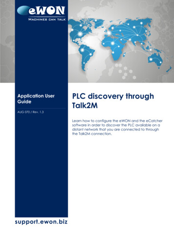
Overshadow PLC to Detect Remote Control-Logic Injection Attacks7Table 1. Extracted riptionThe maximum length of decompiled byte sequenceThe number of the identified opcodesThe number of the identified rungsThe number of the n-grams that are present in a bloom filter (1 n 20)The longest continuous match of n-grams that are present in a bloom filter (1 n 20)The byte entropy of scan eN-gramLowRungEntropyFig. 2. Varying level of semantic knowledge on control logic codedecompiled byte sequence for each position. Then, the longest length is selectedfor the #dec feature.Several studies [1, 3] utilize a disassembler to detect x86 machine code innetwork traffic. Our decompilation approach is in some ways similar to thosestudies. Decompilation of control logic code has a unique characteristic comparedto decompilation of a binary used in common IT systems. When compiling highlevel language code (e.g., C/C , Java) to low-level code (e.g., machine code,bytecode), finding the original structure of the high-level language code from thelow-level code is non-trivial due to compiler optimizations. On the other hand,compilation of control logic code is performed in a manner that it is completelyreversible, i.e., decompilation of logic code recovers the exact source code. Thisinteresting design feature of control logic compilers makes it possible for theengineering software to show the original source code to PLC programmers orICS operators when the control logic is retrieved from a PLC.In our experience (with two engineering software, RSLogix and So-machinebasic of two different vendors, Allen-Bradley and Schneider Electric on twoPLCs, MicroLogix 1400 and M221), we find substantial one-to-one mappingsbetween the high-level language code of two PLC languages (i.e., Ladder Logic,and Instruction List) and their (compiled) low-level code. This key discoveryallows Shade to utilize a substitution table for decompilation. The extent of decompilation can differ between the engineering software. In some cases, decompilation of control logic code not only requires code blocks but also configurationblocks. For example, operands of instructions in code blocks may only be offsetsfrom base addresses, with the base addresses stored in configuration blocks. Ifconfiguration block is not available, the full-decompilation is impossible. In thesecases, Shade performs partial-decompilations.Figures 3(a) shows an example of a full-decompilation for the Modicon M221PLC. Each high-level language code is always mapped to the same low-levelrepresentation. For example, a Ladder Logic instruction XIC I0.1 (examine ifinput 1 is closed) is always mapped to (or compiled to) its low-level representation 0x7c1c which is an RX630 machine instruction [26].Partial Decompilation of Control Logic Code. On the other hand, afull-decompilation of the MicroLogix 1400 logic code requires additional information from a configuration block as well as code blocks [24]. Since an at-
8Yoo et al.: The bytes that can’t be decompiled withoutconfiguration blocksOTE M1XIC I0.1 AND XIC I0.8 (end of rung)XIC M307Rung start7c 1c 23 04 7c 8c fc e6 72 00 00 f6 73 26 00fc ea 72 3e 00OTE M498 (end of rung)decompiled toRung 0: XIC I0.1 AND XIC I0.8 OTE M1Rung 1: XIC M307 OTE M498(a) Full Decompilation (M221)000a000100040003Rung size XIC8ddabecc9a4ff74f200D160300 e4 0000 58 0100 e4 0000FileNo.WordBitOffset OffsetXIO00 01 bc 4f 00 00 e8 000a 00 96 04 ce 4f 00 000a 04 ce 4f 0e 00 bc 00XIC TONFile No. (timer)OTEdecompiled toRung 0: XIC I1:[bc4f]/0 AND XIO T4:[da4f]/DN TON T4:[ce4f]/0Rung 1: XIC T4:[ce4f]/TT OTE B3:[cc4f]/3(b) Partial Decompilation (MicroLogix 1400)Fig. 3. Examples of full and partial decompilation of control logictacker does not necessarily send configuration blocks to a PLC for controllogic injection, we should not assume that Shade can obtain the configuration blocks for decompilation. Figure 3(b) shows an example describing howShade performs a partial-decompilation for the MicroLogix 1400 PLC. Thereare two rungs (Rung 0 and Rung 1), each of which starts with the rung startsignature 0x0000 in low-level code. In Rung 1, Shade decompiles 0xe400 toXIC since the opcodes of Ladder Logic instructions of MicroLogix 1400 arealways mapped to the same low-level code [24]. The system also knows theoperand type of the XIC instruction is the timer object based on its file number (0x04). However, since control logic can have multiple timer objects, Shadedoes not know the timer object that corresponds to the XIC instruction. Theengineering software of the MicroLogix 1400 PLC calculates the exact operandby (W ord of f set Base address)/Size of object where the base addresses ofeach object type is stored in the configuration block.Shade leaves the low-level codes of those operands but counts the numberof decompiled bytes as if the corresponding bytes are decompiled when they arebetween decompiled byte sequences. In the above example, the 2-byte hex valueshighlighted in bold are the operands that can not be decompiled without theconfiguration block. But Shade counts the number of decompiled bytes as 54(the total size of Rung 0 and Rung 1), even though parts of operands are notactually decompiled. Importantly, the purpose of decompilation in Shade is notrecovering the source code, rather counting the number of decompiled bytes.Opcode & Rung Identification. Control logic code consists of one or morerungs and a rung consists of one or more instructions. Typically, a rung has input(e.g., Examine-if-closed:XIC, Examine if open:XIO) and output (e.g., Outputenergize:OTE, Output Latch:OTL, Timer-on-delay:TON) instructions where alogical expression of the inputs is evaluated and the state of the outputs arechanged based on the evaluation result in each PLC scan cycle.To count the number of opcodes, Shade finds all occurrences of opcodes inthe scan area, utilizing a table containing the mapping of opcodes between highlevel code and low-level code. Unlike decompilation, the opcode identificationdoes not utilize other semantics of logic code (e.g., rung structures). The rungsof control logic code are identified based on the knowledge of rung structures. Inthe case of MicroLogix 1400, rungs explicitly start with a signature (0x0000),followed by a field specifying the size of rung. On the other hand, the logic code
Overshadow PLC to Detect Remote Control-Logic Injection Attacks9of the Modicon M221 PLC can be separated into rungs in a different way. Wewill discuss this in detail later in Section 4.N-gram Bloom filter & Entropy. A common method in natural languageprocessing, N-gram analysis extracts features from data without any semanticknowledge or the format of data. This method has been employed in a varietyof applications, including packet payload inspection [2, 4]. Two primary approaches allow the construction an n-gram feature space from a packet payload:1) counting the frequency of each n-gram, 2) counting the n-gram membershipin a pre-defined n-gram setCounting the n-gram frequency. In this approach, payload data is embeddedin a vector space of 256n dimension where n is the size of n-gram. This approachsuffers when n is greater than 1, resulting in a sparse matrix being used fortraining a classifier. This is due to the large vector space compared to the typicalpayload sizes of PLC protocols2 .Counting the n-gram membership in a pre-defined n-gram set. The secondapproach counts the number of n-grams that present or absent in a pre-definedn-gram set. For example, Anagram [4] stores all the unique n-grams of the normalpacket payload in a bloom filter in the training phase, then counts the numberof the n-grams of a testing packet payload that are absent in the bloom filter,to score the abnormality of each packet. Fortunately, the feature space of datain this approach is simply one-dimensional regardless of the size of the n-gram,which allows a higher order n-gram to be used. Generally, a high order n-gram (n 1) is more precise than a 1-gram to detect anomalous packets. This approachalso provides more resistance against mimicry attacks [4].Building off its advantages, Shade employs the latter approach to extracttwo different types of n-gram features (i.e., #Ngram, LNgram). Before traininga classifier, Shade stores in bloom filters all the unique n-grams of normal writerequest message payload containing logic code, for each n-gram size (1 n 20). Then, Shade extracts two different types of n-gram features utilizing thebloom filters: 1) the number of n-grams present in the corresponding n-grambloom filter, 2) the maximum number of consecutive n-grams in the bloom filter.For the entropy feature, Shade calculates the Shannon Entropy of the bytevalue of the payload data.3.3 Feature Selection & ClassificationIn the training phase, we evaluate each feature individually using a one-dimensionalGaussian Naive Bayes classifier [21] to select the best features for generatingclassification models. We employ two classic, explainable machine learning algorithms: 1) Gaussian Naive Bayes and 2) Support Vector Machine (SVM). Withthese algorithms, we then generate classification models and compare the detection performance of each. As we will show in Section 6, neither algorithmperforms significantly better than the other. Critically, however, the use (ornon-use) of shadow memory contributed significantly to the success of attackdetection within the ICS environment.2The maximum payload sizes are 236 bytes and 80 bytes for the Modicon M221 PLCand the MicroLogix 1400 PLC, respectively
104Yoo et al.ImplementationWe implement Shade for two different vendors’ PLCs, Schneider Electric Modicon M221 and Allen Bradley MicroLogix 1400. To demonstrate the effectivenessof Shade against both Data Execution, and Fragmentation and Noise Paddingattacks, we evaluate and compare both Shade and traditional deep packet inspection (DPI). Specifically, Shade extracts features from the scan area of shadowmemory while the DPI extracts them from the packet payload. To allow easyreproducibility, we leverage Python using the open-source Scapy packet manipulation library.4.1 Shade implementation for the M221 PLCM221 Opcode & Rung Identification. To identify opcodes in the M221logic code, we developed a table which maps the opcodes of Instruction Listto its low-level code. For the rung identification, we utilize the following rule ofrung structure applied to the M221 logic code. We separate rungs in two cases: 1)after an output instruction (e.g., ST %Q0.0 to energize coil 0) directly followedby an input instruction (e.g., LD %I0.0 to examine if input 0 is closed), 2) afterthe signature, 0x7f1a11, which represents the end of block.Full-Decompilation of M221 Logic Code. Since all the necessary information to recover the original source code is contained in the code block of the M221control logic, Shade can perform a full-decompilation. Along with a substitutiontable which maps Instruction List code to its low-level code, Shade employs theknowledge of the code’s block structure.The M221 logic code contains three types of blocks: function blocks, comparison blocks, and operation blocks. The M221 PLC uses pre-defined functionblocks such as TON(Timer On-Delay) and CTU(Counter up). A function blockstarts with the signature 0x7f1a10. The comparison blocks provide relationaloperations (e.g., , ), while the operation blocks provide arithmetic an
Overshadow PLC to Detect Remote Control-Logic Injection Attacks Hyunguk Yoo 1, Sushma Kalle , Jared Smith2, and Irfan Ahmed;3 1 University of New Orleans, New Orleans LA 70148 fhyoo1,skalle1g@uno.edu 2 Oak Ridge National Laboratory, Oak Ridge, TN 37830 smithjm@ornl.gov 3 Virginia Commonwealth University, Richmond VA 23221 iahmed3@vcu.edu Abstract. Programmable logic controllers (PLCs) in .