Transcription
INSTALLATION INSTRUCTIONSFOR INDUCED DRAFT GAS FURNACES80PS UPFLOW/HORIZONTAL SERIES80LS DOWNFLOW SERIESUpflow ModelsModel EDR**80PS10NDR**80PS12EDR**80PS15EDR**Input 5Downflow ModelsModel 80LS10ECR**80LS10EDR**80LS12EDR**80LS15EDR**Input 0150,000Tons343355.555U.L. recognized fuel gas and CO (carbon monoxide) detectors are recommended inall applications, and their installation should be in accordance with themanufacturer’s recommendations and/or local laws, rules, regulations, or customs.92-24161-61-00
Before beginning any troubleshooting procedure, complete the following installation checklist. A furnace malfunction issometimes caused by an improper installation. By completing this checklist, the problem may be found and corrected. Makecopies of the checklist and complete one for every Low Profile Furnace service call for your records.INSTALLATION CHECKLIST(Refer to this manual for specifics.)GAS SUPPLYAdequate pipe sizeNo gas leaksProper supply and manifold gas pressure (check with an accurate U-tube manometer with the furnace and all other gasappliances operating.)ELECTRICALCorrect thermostat and subbaseThermostat modelSubbase modelCorrect thermostat mode and settingCorrect line supply voltageCorrect power supply polarity is required with electronic ignitionCorrect furnace ground to electrical panelDC microamp (μA) flame signal (hot surface ignition units)Correct control voltageMeasure and set heat anticipator amperageAir conditioning low voltage wires connected to terminals “Y” “C” - not with wire nutsVENTINGCorrect vent pipe diameter and length (according to CSA tables)Vent connection sizeCorrect venting material (according to CSA tables)Correct lining for masonry chimneysAdequate clearance from combustiblesProper negative pressure reading in the ventVent pipe secured to induced draft blower housingCOMBUSTION AIRProper source of combustion airCorrect combustion air opening sizeOptional attic combustion air pullNon-attic combustion air pullFURNACE INSTALLATIONAdequate clearance from combustiblesAdequate clearance for serviceProper air temperature rise (See furnace rating plate)External static pressureinches w.c.Correct filter(s)Correct cooling coil or accessories (if equipped)Adequate supply and return air ductingAir ducts sealed to prevent leakage2Return Air Duct SizeSupply Air Duct Size
Important: All manufacturer productsmeet current Federal OSHA Guidelinesfor safety. California Proposition 65warnings are required for certainproducts, which are not covered by theOSHA standards.CONTENTSCalifornia's Proposition 65 requireswarnings for products sold in Californiathat contain, or produce, any of over600 listed chemicals known to the Stateof California to cause cancer or birthdefects such as fiberglass insulation,lead in brass, and combustion productsfrom natural gas.General Information .5All “new equipment” shipped for sale inCalifornia will have labels stating thatthe product contains and/or producesProposition 65 chemicals. Although wehave not changed our processes,having the same label on all ourproducts facilitates manufacturing andshipping. We cannot always know“when, or if” products will be sold in theCalifornia market.Installation Check List .2Safety Information .4Location Requirements and Considerations .6Combustion and Ventilation Air.11Vent Pipe Installation .15Gas Supply and Piping .18Electrical Wiring .22Thermostat .22Accessories.23Furnace Twinning .23High Altitude Installations.24You may receive inquiries fromcustomers about chemicals found in, orproduced by, some of our heating andair-conditioning equipment, or found innatural gas used with some of ourproducts. Listed below are thosechemicals and substances commonlyassociated with similar equipment inour industry and other manufacturers.Start-Up Procedure .27 Troubleshooting .35Glass Wool (Fiberglass) InsulationCarbon Monoxide (CO)FormaldehydeBenzeneMore details are available at theWebsites for OSHA (OccupationalSafety and Health Administration), atwww.osha.gov and the State ofCalifornia's OEHHA (Office ofEnvironmental Health HazardAssessment), at www.oehha.org.Consumer education is important sincethe chemicals and substances on thelist are found in our daily lives. Mostconsumers are aware that productspresent safety and health risks, whenimproperly used, handled andmaintained.Air Flow .29Blower Performance Data .30Safety Features.31Maintenance .32Wiring Diagram .36IMPORTANT: TO INSURE PROPER INSTALLATION AND OPERATION OFTHIS PRODUCT, COMPLETELY READ ALL INSTRUCTIONS PRIOR TOATTEMPTING TO ASSEMBLE, INSTALL, OPERATE, MAINTAIN OR REPAIRTHIS PRODUCT. UPON UNPACKING OF THE FURNACE, INSPECT ALLPARTS FOR DAMAGE PRIOR TO INSTALLATION AND START-UP.3
SAFETY INFORMATION!WARNINGUSE ONLY WITH TYPE OF GASAPPROVED FOR THIS FURNACE.REFER TO THE FURNACE RATINGPLATE.!WARNINGINSTALL THIS FURNACE ONLY INA LOCATION AND POSITION ASSPECIFIED IN THE LOCATIONREQUIREMENTS ANDCONSIDERATIONS SECTION OFTHESE INSTRUCTIONS.!WARNINGPROVIDE ADEQUATECOMBUSTION AND VENTILATIONAIR TO THE FURNACE SPACE ASSPECIFIED IN THE VENTINGSECTION OF THESEINSTRUCTIONS.! WARNINGCOMBUSTION PRODUCTS MUSTBE DISCHARGED OUTDOORS.CONNECT THIS FURNACE TO ANAPPROVED VENT SYSTEM ONLY,AS SPECIFIED IN VENT PIPEINSTALLATION SECTION OFTHESE INSTRUCTIONS.! WARNINGTHE MANUFACTURER IS NOTRESPONSIBLE FOR EQUIPMENTTHAT IS MISMATCHED ORIMPROPERLY INSTALLED.!WARNINGNEVER TEST FOR GAS LEAKSWITH AN OPEN FLAME. USE ACOMMERCIALLY AVAILABLESOAP SOLUTION MADESPECIFICALLY FOR THEDETECTION OF LEAKS TO CHECKALL CONNECTIONS, ASSPECIFIED IN GAS SUPPLY ANDPIPING SECTION OF THESEINSTRUCTIONS.4!WARNINGALWAYS INSTALL FURNACE TOOPERATE WITHIN THEFURNACE'S INTENDEDTEMPERATURE-RISE RANGEWITH A DUCT SYSTEM WHICHHAS AN EXTERNAL STATICPRESSURE WITHIN THEALLOWABLE RANGE, ASSPECIFIED IN DUCTING SECTIONOF THESE INSTRUCTIONS. SEEALSO FURNACE RATING PLATE.!WARNINGWHEN A FURNACE IS INSTALLEDSO THAT SUPPLY DUCTS CARRYAIR CIRCULATED BY THEFURNACE TO AREAS OUTSIDETHE SPACE CONTAINING THEFURNACE, THE RETURN AIRSHALL ALSO BE HANDLED BYDUCT(S) SEALED TO THEFURNACE CASING ANDTERMINATING OUTSIDE THESPACE CONTAINING THEFURNACE.!WARNINGWHEN THIS FURNACE ISINSTALLED IN A RESIDENTIALGARAGE, IT MUST BE INSTALLEDSO THE BURNERS AND IGNITIONSOURCE ARE LOCATED NO LESSTHAN 18 INCHES ABOVE THEFLOOR. THIS IS TO REDUCE THERISK OF IGNITING FLAMMABLEVAPORS WHICH MAYBE PRESENT IN A GARAGE.ALSO, THE FURNACE MUST BELOCATED OR PROTECTED TOAVOID PHYSICAL DAMAGE BYVEHICLES. FAILURE TO FOLLOWTHESE WARNINGS CAN CAUSE AFIRE OR EXPLOSION, RESULTINGIN PROPERTY DAMAGE,PERSONAL INJURY OR DEATH.!WARNINGUSE OF THIS FURNACE ISALLOWED DURINGCONSTRUCTION IF THEFOLLOWING TEMPORARYINSTALLATION REQUIREMENTSARE MET. INSTALLATION MUSTCOMPLY WITH ALLINSTALLATION INSTRUCTIONSINCLUDING: PROPER VENT INSTALLATION; FURNACE OPERATING UNDERTHERMOSTATIC CONTROL; RETURN AIR DUCT SEALED TOTHE FURNACE; AIR FILTERS IN PLACE; SET FURNACE INPUT RATEAND TEMPERATURE RISE PERRATING PLATE MARKING; MEANS FOR PROVIDINGOUTDOOR AIR REQUIRED FORCOMBUSTION; RETURN AIR TEMPERATUREMAINTAINED BETWEEN 55 F(13 C) AND 80 F (27 C); AND CLEAN FURNACE, DUCT WORKAND COMPONENTS UPONSUBSTANTIAL COMPLETION OFTHE CONSTRUCTIONPROCESS, AND VERIFYFURNACE OPERATINGCONDITIONS INCLUDINGIGNITION, INPUT RATE,TEMPERATURE RISE ANDVENTING, ACCORDING TO THEINSTRUCTIONS.
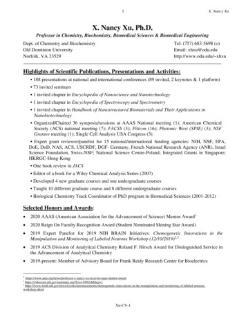
GENERAL INFORMATIONThe 80% gas furnaces are designcertified by CSA for use with natural andpropane gases as follows:As a Category I furnace, it may bevented vertically with type B-1 ventpipe and also may be commonvented as described in theseinstructions.This furnace should be installed inaccordance with the American NationalStandard Z223.1 - latest edition bookletentitled “National Fuel Gas Code”(NFPA 54) (in Canada, CSA B149.1 and.2 Installation Codes for gas burningappliances), and the requirements orcodes of the local utility or otherauthority having jurisdiction includinglocal plumbing or waste water codes.The National Appliance EnergyConservation Act (NAECA) of 1987states that any gas furnacemanufactured after January 1, 1992,must have a minimum Annual FuelUtilization Efficiency (AFUE) of 78%.The higher the AFUE percentage themore usable heat energy the consumergets for every dollar of fuel purchased.This is similar to the EPA's minimum gasmileage requirement for automobiles. Itgives the consumer a relatively easyway to make direct efficiencycomparisons between different furnacebrands and styles.A high AFUE value, which translates intoa low operating cost, is not the onlyconcern that consumers have. They alsowant a furnace with a reasonableinstalled cost. They want a furnace thatprovides them with comfort – their mainconcern. And they expect a furnace withexceptional reliability and longevity.Gas furnace manufacturers are alwaysstriving to provide consumers with thebest furnace value. The Low ProfileFurnace addresses all those consumerneeds. It gives exceptional efficiencywith a low installation cost. It delivers thecomfort the customer wants along withthe reliability they expect.The key to all these customer benefits isthe furnace's heat exchanger. Thematerials used to construct the furnacein general and the heat exchanger inparticular make it a rugged, long lastingunit. The unique heat exchanger designprovides the customer with a furnaceonly 34 inches high. This gives theconsumer a unit easily installed inalmost every location that accepts allcustomary accessories.With the introduction of higher efficiencyfurnaces, special attention must be paidto the venting system. Only listedventing systems may be used as statedin the installation instructions and theNational Fuel Gas Code, ANSI Z223.1(NFPA 54), or the Canadian CAN/CGAB149.1 and B149.2 Installation Codesfor Gas Burning Appliances. Sincefurnace technology and ventingrequirements are changing, awarenessof local, state, and federal codes andindustry changes is imperative.NOTE: Always perform a proper heatloss calculation before specifying thefurnace size. This ensures that thefurnace is sized to adequately,economically, heat the building andprovide the correct airflow for yourapplication.IMPORTANT: PROPER APPLICATION,INSTALLATION AND MAINTENANCEOF THIS FURNACE IS A MUST IFCONSUMERS ARE TO RECEIVE THEFULL BENEFITS FOR WHICH THEYHAVE PAID.Additional helpful publications availablefrom the “National Fire ProtectionAssociation” are: NFPA-90A –Installation of Air Conditioning andVentilating Systems 1985 or latestedition. NFPA-90B – Warm Air Heatingand Air Conditioning Systems 1984.These publications are available from:National Fire Protection Association,Inc.Batterymarch ParkQuincy, MA 02269CSA-INTERNATIONAL178 Rexdale Blvd.Etobicoke (Toronto), OntarioCanada M9W, 1R3FIGURE 1MIGRATION OF DANGEROUS SUBSTANCES, FUMES, AND ODORS INTO LIVING SPACESIMPORTANT INFORMATIONABOUT EFFICIENCY ANDINDOOR AIR QUALITYCentral cooling and heating equipmentis only as efficient as the duct systemthat carries the cooled or heated air. Tomaintain efficiency, comfort and goodindoor air quality, it is important to havethe proper balance between the airbeing supplied to each room and the airreturning to the cooling and heatingequipment.Proper balance and sealing of the ductsystem improves the efficiency of theheating and air conditioning systemand improves the indoor air quality ofthe home by reducing the amount ofairborne pollutants that enter homesfrom spaces where the ductwork and /or equipment is located. Themanufacturer and the U.S.Environmental Protection Agency’sEnergy Star Program recommend thatcentral duct systems be checked by aqualified contractor for proper balanceand sealing.!WARNINGDUCT LEAKS CAN CREATE ANUNBALANCED SYSTEM AND DRAWPOLLUTANTS SUCH AS DIRT,DUST, FUMES AND ODORS INTOTHE HOME CAUSING PROPERTYDAMAGE. FUMES AND ODORSFROM TOXIC, VOLATILE ORFLAMMABLE CHEMICALS, AS WELLAS AUTOMOBILE EXHAUST ANDCARBON MONOXIDE (CO), CAN BEDRAWN INTO THE LIVING SPACETHROUGH LEAKING DUCTS ANDUNBALANCED DUCT SYSTEMSCAUSING PERSONAL INJURY ORDEATH (SEE FIGURE 1). IF AIR-MOVING EQUIPMENT ORDUCTWORK IS LOCATED INGARAGES OR OFF-GARAGESTORAGE AREAS - ALL JOINTS,SEAMS, AND OPENINGS IN THEEQUIPMENT AND DUCT MUST BESEALED TO LIMIT THEMIGRATION OF TOXIC FUMESAND ODORS INCLUDING CARBONMONOXIDE FROM MIGRATINGINTO THE LIVING SPACE.5
IF AIR-MOVING EQUIPMENT ORDUCTWORK IS LOCATED INSPACES CONTAINING FUELBURNING APPLIANCES SUCH ASWATER HEATERS OR BOILERS ALL JOINTS, SEAMS, ANDOPENINGS IN THE EQUIPMENTAND DUCT MUST ALSO BESEALED TO PREVENTDEPRESSURIZATION OF THESPACE AND POSSIBLEMIGRATION OF COMBUSTIONBYPRODUCTS INCLUDINGCARBON MONOXIDE INTO THELIVING SPACE.NOTICEIMPROPER INSTALLATION, ORINSTALLATION NOT MADE INACCORDANCE WITH THEUNDERWRITERS LABORATORY(UL) CERTIFICATION OR THESEINSTRUCTIONS, CAN RESULT INUNSATISFACTORY OPERATIONAND/OR DANGEROUS CONDITIONS AND ARE NOT COVERED BYTHE UNIT WARRANTY.NOTICEIN COMPLIANCE WITHRECOGNIZED CODES, IT ISRECOMMENDED THAT ANAUXILIARY DRAIN PAN BEINSTALLED UNDER ALLEVAPORATOR COILS OR UNITSCONTAINING EVAPORATOR COILSTHAT ARE LOCATED IN ANY AREAOF A STRUCTURE WHEREDAMAGE TO THE BUILDING ORBUILDING CONTENTS MAY OCCURAS A RESULT OF AN OVERFLOW OFTHE COIL DRAIN PAN OR ASTOPPAGE IN THE PRIMARYCONDENSATE DRAIN PIPING. SEEACCESSORIES SECTION OF THESEINSTRUCTIONS FOR AUXILIARYHORIZONTAL OVERFLOW PANINFORMATION (MODEL RXBM).RECEIVINGImmediately upon receipt, all cartonsand contents should be inspected fortransit damage. Units with damagedcartons should be opened immediately.If damage is found, it should be notedon the delivery papers, and a damageclaim filed with the last carrier. After unit has been delivered to jobsite, remove carton taking care not todamage unit. Check the unit rating plate for unitsize, electric heat, coil, voltage,phase, etc. to be sure equipmentmatches what is required for the jobspecification. Read the entire instructions beforestarting the installation. Some building codes require extracabinet insulation and gasketingwhen unit is installed in atticapplications. If installed in an unconditioned space,apply caulking around the powerwires, control wires, refrigerant tubingand condensate line where they enter the cabinet. Seal the power wires onthe inside where they exit conduitopening. Caulking is required toprevent air leakage into andcondensate from forming inside theunit, control box, and on electricalcontrols.Install the unit in such a way as toallow necessary access to thecoil/filter rack and blower/controlcompartment.Install the unit in a level position toensure proper condensate drainage.Make sure unit is level in bothdirections within 1/8”.Install the unit in accordance withany local code which may apply andthe national codes. Latest editionsare available from: “National FireProtection Association, Inc.,Batterysmarch Park, Quincy, MA02269.” These publications are:ANSI/NFPA No. 70-(Latest Edition)National Electrical Code.NFPA90A Installation of AirConditioning and VentilatingSystems.NFPA90B Installation of warm airheating and air conditioning systems.The equipment has been evaluatedin accordance with the Code ofFederal Regulations, Chapter XX,Part 3280.LOCATION REQUIREMENTS AND CONSIDERATIONSGENERAL INFORMATION1. NOTE: This furnace is shipped withheat exchanger support bracketsinstalled under the back of the heatexchanger. These may be removedbefore installation, but it is notrequired.LOCATION! WARNINGTHIS FURNACE IS NOT APPROVEDFOR INSTALLATION IN A MOBILEHOME. DO NOT INSTALL THISFURNACE IN A MOBILE HOME.INSTALLATION IN A MOBILE HOMECOULD CAUSE FIRE, PROPERTYDAMAGE, PERSONAL INJURY ORDEATH.2. IMPORTANT: This furnace is notapproved or recommended forinstallation on its back, with accessdoors facing upwards.3. This furnace is suitable forinstallation in buildings constructedon-site. This heating unit should becentralized with respect to the heatdistribution system as much aspracticable.4. NOTE: These furnaces areapproved for installation in attics, as6well as alcoves, utility rooms,closets and crawlspaces.5. IMPORTANT: Support this unit wheninstalled. For attic or crawl spaceinstallation, horizontal furnaces maybe installed on combustible woodflooring or by using support brackets.See Figure 2.6. IMPORTANT: If installing in a utilityroom, be sure the door is wideenough to:a. allow the largest part of thefurnace to pass; orb. allow any other appliance (suchas a water heater) to pass.FIGURE 2HORIZONTAL FURNACE INSTALLED W/SUPPORT BRACKETSEXHAUSTVENTNOTE: Do not block furnaceaccess with support rods. Maintainclearances recommended in Figure 2.Allow enough space for proper servicemaintenance or replacement of the heatexchanger and blower assembly.ST-A0799-01
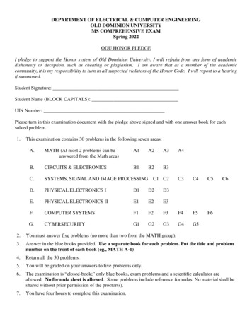
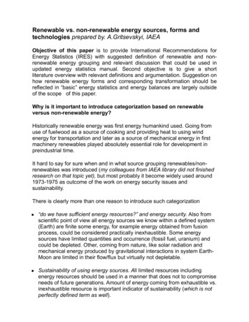
F265/8GAS CONNECTION2613/16CSUPPLYAIR111/2143/81124 /32ERETURNAIR10010012515034.5 & 555/3275503&43Tons2311/32241/2BA2311/32241/214 /819 /322134/32/4319157/8157/81123/8271611/32171/212 /816 /323105/8C17 /21227/32B11114AFRONTInputkBtu1518 0002411/32111/2RIGHT SIDE14 /83ALTERNATEGAS ➂Vent150 lbs.140 lbs.120 lbs.115 lbs.105 lbs.85 lbs.Ship.Wgts.23/8 DIA./8 DIA.715/8 DIA.265/8720247/16281/16➀ May require 3” to 4” or 3” or 5” adapter.➁ May be 0” with type B vent.➂ May be 1” with type B vent.000000BackREDUCED CLEARANCE (IN.)CLEARANCE TO COMBUSTIBLE MATERIAL (INCHES)UPFLOW/HORIZONTAL MODELSSIGHTGLASS1923 /321711/4AIRFLOWIMPORTANT: This furnace is not approved or recommended forinstallation on its back, with access doors facing upwards.LEFT SIDEOPTIONAL RETURN AIR CUTOUT(EITHER SIDE) FOR USE WITHEXTERNAL SIDE FILTER FRAMELOW VOLTAGE241/2BOTTOM1915/32UPFLOW/HORIZONTAL DIMENSIONSELECTRICAL CONNECTION25.406TOPFIGURE 37
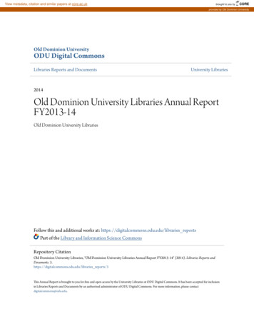
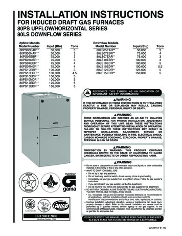
8265/8GAS CONNECTION26 /1613ELECTRIC CONNECTIONLOW 2125513 /819 /32211005 & 5.5121/8271611/32171/21003233/8155/8155/8712 /816 /3217 /2753&4111103/81227/32114503CTonsBAInputkBtuNOTE: IN DOWNFLOW CONFIGURATION, OPTIONAL AIR CUTOUT IS NOT PERMITTED.241/2TOP16 5/816 5/820 1/823 5/823 5/8➀➀➀➀➀63/1613 ��6➂6➂6➂6➂6➂Vent150 lbs.140 lbs.120 lbs.115 lbs.105 lbs.85 lbs.Ship.Wgts.201/8247/16265/8281/16/85➀ May require 3” to 4” or 3” or 5” adapter.➁ May be 0” with type B vent.➂ May be 1” with type B vent.000000BackREDUCED CLEARANCE (IN.)15/8 DIA./8 DIA.7/8 DIA.70003➁3➁4➁RightSideCLEARANCE TO COMBUSTIBLE MATERIAL (INCHES)DOWNFLOW MODELSDOWNFLOW DIMENSIONSFIGURE 4
CLEARANCE –ACCESSIBILITYThe design of forced air furnaces withinput ratings as listed in the tables onthe following pages are certified byCSA for the clearances to combustiblematerials shown in inches.See name/rating plate and clearancelabel for specific model number andclearance information.Service clearance of at least 24 inchesis recommended in front of all furnaces.ACCESSIBILITY CLEARANCES,WHERE GREATER, MUST TAKEPRECEDENCE OVER FIREPROTECTION CLEARANCES.! WARNINGUPFLOW AND HORIZONTALFURNACES MUST NOT BEINSTALLED DIRECTLY ONCARPETING, TILE OR OTHERCOMBUSTIBLE MATERIAL OTHERTHAN WOOD FLOORING.INSTALLATION ON ACOMBUSTIBLE MATERIAL CANRESULT IN FIRE CAUSINGPROPERTY DAMAGE, SEVEREPERSONAL INJURY OR DEATH.A gas-fired furnace for installation in aresidential garage must be installed sothat the burner(s) and the ignitionsource are located not less than 18”above the floor and the furnace islocated or protected to avoid physicaldamage by vehicles.!WARNINGDOWNFLOW UNIT DESIGN ISCERTIFIED FOR INSTALLATION ONNON-COMBUSTIBLE FLOOR. ASPECIAL COMBUSTIBLE FLOORSUB-BASE IS REQUIRED WHENINSTALLING ON A COMBUSTIBLEFLOOR. FAILURE TO INSTALL THESUB-BASE MAY RESULT IN FIRE,PROPERTY DAMAGE, PERSONALINJURY OR DEATH. THIS SPECIALBASE IS OFFERED AS ANACCESSORY FROM THE FACTORY.SEE THE CLEARANCE LABELLOCATED INSIDE THE FURNACEFOR THE APPROPRIATE MODELNUMBER.THE SPECIAL BASE IS NOTREQUIRED WHEN THE FURNACE ISINSTALLED ON TOP OF AN AIRCONDITIONING PLENUM.DUCTINGTABLE 1FURNACEWIDTHBASEPLATE D21RXGB-D24BASEPLATE SIZE115/8” x 239/16”151/8” x 239/16”185/8” x 239/16”255/8” x 239/16”SITE SELECTION1. Select a site in the building near thecenter of the proposed, or existing,duct system.2. Give consideration to the vent systempiping when selecting the furnacelocation. Be sure the venting systemcan travel from the furnace to thetermination with minimal length andelbows.3. Locate the furnace near the existinggas piping. Or, if running a new gasline, locate the furnace to minimizethe length and elbows in the gaspiping.4. Locate the furnace to maintain properclearance to combustibles as shownin Figures 3 and 4.!CAUTIONWHEN COILS ARE USED WITH AIRHANDLERS OR FURNACES ANDINSTALLED ABOVE A FINISHEDCEILING OR LIVING AREA, IT ISRECOMMENDED THAT ANAUXILIARY SHEET METALCONDENSATE DRAIN PAN BEFABRICATED AND INSTALLEDUNDER ENTIRE UNIT. FAILURE TODO SO CAN RESULT IN PROPERTYDAMAGE. RUN CONDENSATE TO ALOCATION WHERE IT ISNOTICEABLE.!WARNINGCOMBUSTIBLE MATERIAL MUSTNOT BE PLACED ON OR AGAINSTTHE FURNACE JACKET OR WITHINTHE SPECIFIED CLEARANCES OFTHE VENT PIPE. THE AREA AROUNDTHE FURNACE MUST BE KEPTCLEAR AND FREE OF ALLCOMBUSTIBLE MATERIALSINCLUDING GASOLINE AND OTHERFLAMMABLE VAPORS AND LIQUIDS.PLACEMENT OF COMBUSTIBLEMATERIALS ON, AGAINST ORAROUND THE FURNACE JACKETCAN CAUSE AN EXPLOSION ORFIRE RESULTING IN PROPERTYDAMAGE, PERSONAL INJURY ORDEATH. THE FURNACE OWNERSHOULD BE CAUTIONED THAT THEFURNACE AREA MUST NOT BEUSED AS A BROOM CLOSET ORFOR ANY OTHER STORAGEPURPOSES.Proper air flow is required for thecorrect operation of this furnace. Toolittle air flow can cause erraticoperation and can damage the heatexchanger. The duct system mustcarry the correct amount of air forheating and cooling. Position the unitminimize long runs or runs with manyturns and elbows.Size the ducts according to acceptableindustry standards and methods. Thetotal static pressure drop (includingevaporator coil, if used) of the entiresystem should not exceed 0.5” w.c. Besure to have adequate space for unitfilter. NOTE: Airflow external staticpressure measurements do not includefilter or coil.IMPORTANT: Some high efficiencyfilters have a greater than normalresistance to air flow. This canadversely affect furnace operation. BESURE TO CHECK AIR FLOW if usingany filter other than the factoryprovided filter.NOTE: DO NOT take return air frombathrooms, kitchens, furnace rooms,garages, utility or laundry rooms, orcold areas.IMPORTANT: When using outside air,design and adjust the system tomaintain a return air temperatureabove 50 F during the heating season.!WARNINGNEVER ALLOW PRODUCTS OFCOMBUSTION OR THE FLUEPRODUCTS TO ENTER THERETURN AIR DUCTWORK, OR THECIRCULATING AIR SUPPLY. ALLRETURN DUCTWORK MUST BEADEQUATELY SEALED ANDSECURED TO THE FURNACE WITHSHEET METAL SCREWS, ANDJOINTS TAPED. WHEN A FURNACEIS MOUNTED ON A PLATFORM,WITH RETURN THROUGH THEBOTTOM, IT MUST BE SEALEDAIRTIGHT BETWEEN THE FURNACEAND THE RETURN AIR PLENUM.THE RETURN AIR PLENUM MUSTBE PERMANENTLY ENCLOSED.NEVER USE A DOOR AS A PART OFTHE RETURN AIR PLENUM. THEFLOOR OR PLATFORM MUSTPROVIDE SOUND PHYSICALSUPPORT OF THE FURNACE,WITHOUT SAGGING, CRACKS,GAPS, ETC., AROUND THE BASEAS TO PROVIDE A SEAL BETWEENTHE SUPPORT AND THE BASE.9
FAILURE TO PREVENT PRODUCTSOF COMBUSTION FROM BEINGCIRCULATED INTO THE LIVINGSPACE CAN CREATE POTENTIALLYHAZARDOUS CONDITIONS,INCLUDING CARBON MONOXIDEPOISONING THAT COULD RESULTIN PERSONAL INJURY OR DEATH.DO NOT, UNDER ANYCIRCUMSTANCES, CONNECTRETURN OR SUPPLY DUCTWORKTO OR FROM ANY OTHER HEATPRODUCING DEVICE SUCH AS AFIREPLACE INSERT, STOVE, ETC.DOING SO MAY RESULT IN FIRE,CARBON MONOXIDE POISONING,EXPLOSION, PERSONAL INJURYOR PROPERTY DAMAGE.!WARNINGBLOWER AND BURNERS MUSTNEVER BE OPERATED WITHOUTTHE BLOWER DOOR IN PLACE.THIS IS TO PREVENT DRAWINGGAS FUMES (WHICH COULDCONTAIN HAZARDOUS CARBONMONOXIDE) INTO THE HOME THATCOULD RESULT IN PERSONALINJURY OR DEATH.UPFLOW UNITS1. Set furnace in place and connect thereturn duct or return air cabinet tounit. Make the connection air-tight toprevent entraining combustiongases from any adjacent fuelburning appliances. Unit return airmay be connected on the sides orbottom of the return aircompartment.a. Openings in the side must be cutout the full width of the knockoutson the unit. If using side return air,THE BOTTOM base plate mustbe installed.NOTE: Where the maximumairflow is 1800 CFM or more, bothsides or the bottom must be usedfor return air.b. If using bottom return air, placefurnace over return air plenum andseal furnace bottom to return airplenum.10!WARNINGA SOLID METAL BASE PLATE, (SEETABLE 1) MUST BE IN PLACEWHEN THE FURNACE ISINSTALLED WITH SIDE AIRRETURN DUCTS. FAILURE TOINSTALL A BASE PLATE COULDCAUSE PRODUCTS OFCOMBUSTION TO BE CIRCULATEDINTO THE LIVING SPACE ANDCREATE POTENTIALLYHAZARDOUS CONDITIONS,INCLUDING CARBON MONOXIDEPOISONING OR DEATH.2. If summer air conditioning is desired,position the indoor coil on the supplyair side of the furnace. Insure that noair can bypass this coil.3. Connect the supply air plenum to thefurnace plenum opening.DOWNFLOW UNITS!WARNINGTHE DOWNFLOW FURNACEDESIGN IS CERTIFIED FORINSTALLATION ON A NONCOMBUSTIBLE FLOOR. IFINSTALLED ON A COMBUSTIBLEFLOOR, USE THE SPECIAL BASESPECIFIED ON THE FURNACECLEARANCE LABEL. FAILURE TOINSTALL THE SPECIAL BASE MAYRESULT IN FIRE, PROPERTYDAMAGE, PERSONAL INJURY ORDEATH. THIS SPECIAL BASE ISSHIPPED FROM THE FACTORY ASAN ACCESSORY.1. Position the unit over the supply airplenum and connect.a. If installing on a combustible floorand not using an evaporatorcoil box, install the specialcombustible floor base. SeeFigure 5.FIGURE 5COMBUSTIBLE FLOOR BASEb. If summer air conditioning isdesired, position the indoor coil onthe bottom of the unit. Insure thatno air can bypass this coil.2. Connect the return air ducting to thereturn air opening at the top of theunit. Make the connection air tight toprevent entraining combustiongases from an adjacent fuel-burningappliance.HORIZONTAL UNITS1. Unit can be mounted left or rightside airflow configuration.2. Position the unit on adequatesupports or by using supportbrackets (see Figure 2) and connectsupply plenum.3. If summer air conditioning is desired,position the indoor coil on the supplyair side of the unit. Insure that no aircan bypass this coil.4. Secure the four angle bracketsshipped with the unit to the return airopening. See Figure 6. Connect thereturn air ducting to the return airopening at the top of the unit. Makethe connection air tight to prevententraining combustion gases froman adjacent fuel-burning appliance.NOTE: Do not block furnace accesswith support rods. Maintain clearancesrecommended in Figure 3. Allowenough space for proper servicemaintenance or replacement of theheat exchanger and blower assembly.
FIGURE 6HORIZONTAL RETURN AIR DUCT(LEFT-HAND AIRFLOW POSITION SHOWN)AIRFLOWCommercial buildingsBuildings with indoor poolsFurnaces installed in laundry roomsFurnaces in hobby or craft roomsFurnaces installed near chemicalstorage areas.Exposure to the following substancesin the combustion air supply may alsorequire OUTDOOR AIR forcombustion:RETURNREAR VIEWFOUR ANGLE BRACKETS ARE SHIPPED WITH EACHUNIT THAT CAN BE INSTALLED HORIZONTALLY. THESEBRACKETS MAY BE USED TO SECURE THE RETURNAIR DUCT TO A HORIZONTAL UNIT.COMBUSTION AND VENTILATION AIRIMPORTANT: This is not a direct vent furnace. Review venting instructionsbefore installing.!WARNINGTHIS FURNACE AND ANY OTHERFUEL-BURNING APPLIANCE MUSTBE PROVIDED WITH ENOUGHFRESH AIR FOR PROPERCOMBUSTION AND VENTILATIONOF THE FLUE GASES. MOSTHOMES WILL REQUIRE THATOUTSIDE AIR BE SUPPLIED INTOTHE FURNACE AREA. FAILURE TODO SO CAN CAUSE DEATH FROMCARBON MONOXIDE POISONING.Adequate facilities for providing air forcombustion and ventilation must beprovided in accordance with section5.3, Air for Combustion andVentilation, of the National Fuel GasCode, ANSI, Z223.1 latest edition orCSA B149.1 and .2 o
furnaces, special attention must be paid to the venting system. Only listed venting systems may be used as stated in the installation instructions and the National Fuel Gas Code, ANSI Z223.1 (NFPA 54), or the Canadian CAN/CGA B149.1 and B149.2 Installation Codes for Gas Burning Appliances. Since furnace technology and venting