Transcription
STAINLESSLITE PLUSHEAT PUMP DUOUNVENTED MAINS PRESSUREHOT WATER STORAGEINSTRUCTION MANUALDESIGN, INSTALLATION & SERVICINGONE NAME. EVERY SOLUTION.GLEDHILL.NETGPL011-IU-Iss03-01/22
These instructions should be read in conjunction with the installation/servicinginstructions issued by the manufacturer of the heat source being used.Any installation must be in accordance with the relevant requirements of the GasSafety Regulations, Building Regulations, I.E.E. Wiring Regulations and the Water FittingRegulations (England and Wales) or Water Byelaws (Scotland). It should be read inaccordance with the relevant recommendations of the following:BS 6798; BS EN 12828, BS EN 12831, BS EN 14336; BS 5546;BS 5440:1; BS 5440:2; CP 331:3BS EN 806-1 to 5, BS EN 8558:2011: BS EN 1458-1:2011 and BS 7593:2006StainlessLite Plus HP DUO is covered by Section G3 of the Building Regulations(England and Wales) Technical Standard P3 (Scotland) and Building RegulationP5 (Northern Ireland). Compliance can be achieved via a Competent Person SelfCertification Scheme or notificaton of installation to the Local Authority BuildingControl Department.It must be installed by a competent person as defined by the relevant regulations.Manufacturers notes must NOT be taken as over-riding statutory obligations.This appliance is not intended for use by persons (including children) with reducedphysical, sensory or mental capabilities, or lack of experience and knowledge unlessthey have been given supervision or instruction concerning use of the appliance bya person responsible for their safety. Children should be supervised at all times toensure they do not play with the appliance.This information is provided to assist generally in the selection of equipment.Responsibility for selection and specification of our equipment must however remainthat of our customer and any experts or consultants concerned with the installation(s).Please note: that we do not therefore accept any responsibility for matters ofdesign selection or specification, for the effectiveness of an installation or systemcontaining one of our products unless specifically requested to do so in writing.All goods are sold subject to our Conditions of Sale which are set out at the rear of thisspecification. In the interest of continuously improving the StainlessLite Plus range,Gledhill Building Products Limited reserve the right to modify the product without notice,and in these circumstances this booklet, which is accurate at the time of printing, shouldbe disregarded. An updated set of Instructions will be produced and supplied with newappliances and will be made available for other appliances on request.StainlessLite Plus is produced under an ISO 9001:2008 Quality ManagementSystem approved by BSI.Benchmark places responsibilities on both manufacturers and installers. The purpose is toensure that customers are provided with the correct equipment for their needs, that it isinstalled, commissioned and serviced in accordance with the manufacturers instructionsby competent persons and that it meets the requirements of the appropriate BuildingRegulations. The Benchmark Checklist can be used to demonstrate compliance withBuilding Regulations and should be provided to the customer for future reference.Installers are required to carry out installation, commissioning and servicing workin accordance with the Benchmark Code of Practice which is available from theHeating and Hot Water Industry Council who manage and promote the Scheme.Visit www.centralheating.co.uk for more information.For further information on the HWA Charter Statement, please refer to the HWA websitehotwater.org.uk.Page 2SectionPageDESIGNDescriptionTechnical InformationSystem USER INSTRUCTIONS23SERVICING AND MAINTENANCEServicing and MaintenanceFault FindingShort Parts List242527APPENDIXAppendix AAppendix B2829Notes30Terms & Conditions32Benchmark ChecklistBenchmark Service Record3435
DESIGNManufacturer: Gledhill Building Products LtdMaintenanceMaximum inlet pressure toPressure reducing valve 12 barOperating pressure (PRV setting)3 barExpansion vessel charge pressure3 barExpansion relief valve setting4.5 barOpening pressure of P & T Relief Valve6 barOpening temperature of P & T Relief Valve89-96 CEnergy cut-out thermostat setting82 CMax. working pressure - Heat pump heat exchanger3 barMax. working pressure - Solar heat exchanger6 barImmersion heater rating3kW, 240V ACModifications should not be made to thisproduct. Replacement par ts, includingimmersion heaters, should be purchased fromGledhill Building Products Limited, or agentsapproved by them. Unvented hot water storagevessels need regular routine checks, andthese are detailed below. It is for this reasonthat this manual must always be left with theStainlessLite Plus HP DUO.All cylinders are manufactured in accordance with the requirements of BS EN 12897The tundish must be positioned so that it is visible to the occupant and is away fromelectrical devices.Components supplied with StainlessLite Plus HP DUO: Cold water inlet PRV combination valve/expansion relief Lift up pressure and temperature relief valve Control thermostat Energy cut-out thermostat Energy cut-out motorised valve (indirects only) Tundish 3kW Immersion heater including control and cut out thermostats Drain elbow and 90 degree elbow, (no elbow on the duo product) Expansion vessel/mounting bracket Technical/user product literature Thermistor cable clampIn any situation where the volume of heated pipework (eg. secondary circulationpipes or manifold pipework for multiple units) exceeds 10 litres, then anadditional expansion vessel must be fitted to accommodate the extra expansionvolume.Handling Before InstallationStainlessLite Plus HP DUO must be handled with care and stored the correct wayup in a dry place. Any manual handling/lifting operations will need to comply withthe requirements of the Manual Handling Operations Regulations issued by the H.S.E.The appliance can be moved using a sack truck on the rear face although care shouldbe taken and the route should be even. In apartment buildings containing a numberof storeys we would recommend that the appliances are moved vertically in a mechanicallift. If it is proposed to use a crane, expert advice should be obtained regarding theneed for slings, lifting beams etc.A specific manual handling assessment is shown in Appendix B at the rear of thismanual.The EnvironmentIt is essential that these checks be carried outat the time of boiler maintenance by a qualifiedinstaller:1. Manually open the relief valves in turn, andcheck that water is discharged from thevalves and runs freely through the tundishand out at the discharge point. Ensure thatthe valves re-seat satisfactorily. (Note - thewater may be very hot).2. It is important to check that the dischargepipework is carrying the water awayadequately. Check for blockages etc. if it isnot.3. Isolate the cold supply to the cylinder.Remove the inlet control group valve.Inspect the guaze filter on the inlet side ofthe valve and remove the debris.4. Check the charge pressure in the expansionvessel and repressurise if required5. Re-fill the system and ensure that all reliefvalves have re-seated.6. The Benchmark Service Record should beupdated at each service.7. Check the water pressure downstream of thecombination valve is 3 bar in static condition.8. Check and if necessary, descale the heatexchanger in hard water areas ie. above200ppm (mg/l).Note:The cylinder is factory fitted with a lift uptemperature & pressure relief valve that mustnot be used for any other purpose or removed.The cylinder is factory fitted with immersionheaters with thermal cut outs. Immersionswithout thermal cut outs must not be fitted.This product has been manufactured using many recyclable materials, including theapproved HCFC/CFC free polyurethane foam insulation. At the end of its useful life, itshould be disposed of at a Local Authority Recycling Centre, to maximise the productsfull environmental benefits.Page 3DESCRIPTION
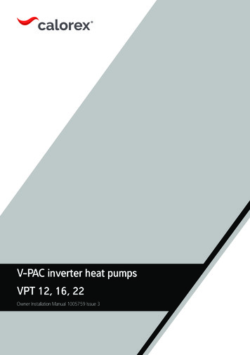
DESIGNTable 1StainlessLite Plus HP SOL ModelProduct Stock CodeHP180INDSOL HP210INDSOL HP250INDSOL HP300INDSOL HP400SEnergy efficiency classwattskWh/24hlitreslitreslitreskgbarbar barminHeat lossCapacity - total volumeVolume heated by IHDedicated solar volumeWeight - empty/fullPressure regulating valve settingExpansion relief valve settingTemperature setting (P&T valve)Pressure setting (P&T valve)Expansion vessel size (volume)Expansion vessel initial charge pressureHeightDiameter22mm secondary return22mm compression cold feedP & T valve22mm solar return - bottom coil22mm solar flow - bottom coil28mm primary return - top coil28mm primary flow - top coilDual CT & OHT pocket - 1Dual CT & OHT pocket - 2Solar sensor pocket - 1Solar sensor pocket - 23kW immersion heater heightSurface area of solar heater coilSolar coil pressure loss 1Primary heat exchanger surface areaPrimary heat exchanger thermal rating 1Primary heat exchanger pressure loss 1Heat up time from 15 C to 60 C 2ABCDEFGHIJKLMN1. Measured at 0.25 l/s primary flow 0434.20.01948C872.0939327013061/46134.59562 x 01.270.312.9147.20.027492. Measured at 0.25 l/s primary flow rate and at 82 C flow temperature15 37,525 DESCRIPTIONFMGDNHJKLCIEANOTESPage 4 35 101. Not all models - seetable 1.2. Recovery times basedon Primary Coil/I.H. duty(ie. assumes the heatpump / solar output isadequate).3. All connectionsare supplied withcompression fittingsfor direct connection tocopper pipework.
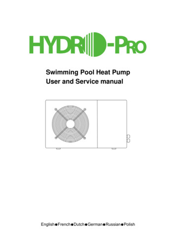
DESIGNTable 2StainlessLite Plus HP ModelProduct Stock CodeEnergy efficiency classHeat lossCapacity - total volumeVolume heated by IHWeight - empty/fullPressure regulating valve settingExpansion relief valve settingTemperature setting (P&T valve)Pressure setting (P&T valve)Expansion vessel size (volume)Expansion vessel initial charge pressureHeightDiameterHot SupplyP & T valve22mm secondary return28mm primary flowHP control thermostat28mm primary returnCold feed3kW immersion heaterDual control / Overheat thermostatPrimary heat exchanger surface areaPrimary heat exchanger capacityPrimary heat exchanger thermal rating 1Primary heat exchanger pressure loss 1Heat up time from 15 C to 50 C 2V40ABCDEFGHIwattskWh/24hlitreslitreskgbarbar 2.58.532.8 (17.8)0.0417.62 (22.56)270 1411245516275220220516310.632.0 (17.5)0.03217.70 (22.17)272 3531270600300220220600310.636.0 (18.0)0.03222.01 (27.34)373 5621290682320220220682310.637.4 (19.0)0.03222.97 (35.05)406 (317)C872.0939337262/46234.59562 x 24320306302080178415771660668330285245668414.139.9 (24.7)0.0730.94 (37.48)603 (444)1. Measured at 0.25 (0.42) l/s primary flow rate2. Measured at 0.25 (0.42) l/s primary flow rate and at 80 (55) C flow temperature, tested to BS EN 12897, figures in brackets show figures forHWA 002:2020 heat pump test resultsNOTES1. Recovery times base on Primary Coil/I.H. duty (ie. assumes the heat pump output is adequate).NOTES 25 35 Page 523 151. Not all models - seetable 2.2. Recovery times basedon Primary Coil/I.H. duty(ie. assumes the heatpump / solar output isadequate).3. All connectionsare supplied withcompression fittingsfor direct connection tocopper pipework.TECHNICAL INFORMATION
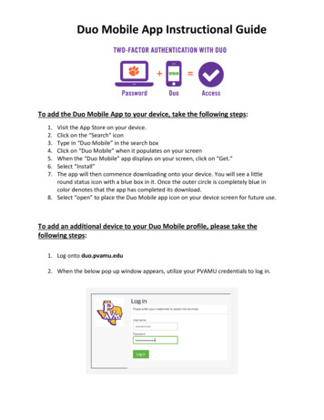
DESIGNTable 3StainlessLite Plus HP Slimline ModelProduct Stock 110.639.3 (20.7)0.01815.75 (21.81)291 3730015856746742203.0110.635.2 (19.9)0.01818.78 (23.68)307 (222)Energy efficiency classHeat lossCapacity - total volumeVolume heated by IHDedicated solar volumeWeight - empty/fullPressure regulating valve settingExpansion relief valve settingTemperature setting (P&T valve)Pressure setting (P&T valve)Expansion vessel size (volume)Expansion vessel initial charge pressureHeightDiameter22mm secondary return22mm compression cold feedP & T valve28mm primary return28mm primary flowHP control thermostatDual CT & OHT pocket3kW immersion heater heightPrimary heat exchanger surface areaPrimary heat exchanger capacityPrimary heat exchanger thermal rating 1Primary heat exchanger pressure loss 1Heat up time from 15 C to 60 C ar itres1. Measured at 0.25 (0.42) l/s primary flow rate2. Measured at 0.25 (0.42) l/s primary flow rate and at 80 (55) C flow temperature, tested to BS EN 12897, figures in brackets show figures forHWA 002:2020 heat pump test results.NOTES 35 TECHNICAL INFORMATIONPage 623 15 1. Not all models - seetable 3.2. Recovery times basedon Primary Coil/I.H.duty (ie. assumes theheat pump output isadequate).3. All connectionsare supplied withcompression fittingsfor direct connection tocopper pipework.
DESIGNTable 4DuoProduct Stock CodeSL Plus CYL/BUF 200/70LPLUHP200DUOSL Plus CYL/BUF r 571235119014401127495265220230310.632.0 (17.5)0.03215.74 03717521330133015101170560310240230310.637.4 (19.0)0.03222.97 (35.05)litres272 (228)406 (317)Energy efficiency classHeat lossCapacity - Cylinder /BufferVolume heated by IHWeight - empty/fullPressure regulating valve settingExpansion relief valve settingTemperature setting (P&T valve)Pressure setting (P&T valve)Expansion vessel size (volume)Expansion vessel initial charge pressureHeightDiameterBuffer ventBuffer connectionsT&P relief valveHot supplyHeat pump flowSecondary returnControl thermostat (x2)Heat pump returnImmersion heaterCold feedPrimary heat exchanger surface area 1Primary heat exchanger capacityPrimary heat exchanger thermal rating 1Primary heat exchanger pressure loss 1Heat up time from 15 C to 50 C 2ABCDEFGHJKV401. Measured at 0.25 (0.42) l/s primary flow rate2. Measured at 0.25 (0.42) l/s primary flow rate and at 80 (55) C flow temperature, tested to BS EN 12897, figures in brackets show figures forHWA 002:2020 heat pump test resultsNOTES1. Recovery times base on Primary Coil/I.H. duty (ie. assumes the heat pump output is adequate).Buffer CH Flow 60 Secondary Return 57.5 Hot Supply 52.5 Buffer CH Return 40 Cold Feed 25 Buffer Inspection Port 20 Buffer HP Flow 35 Cylinder HP Flow & Return 35 Thermistor pocket with clampBuffer HP Return 15 T & P Relief Valve 7.5 Buffer Stat PocketCylinder Stat PocketImmersion HeaterTECHNICAL INFORMATIONPage 7
DESIGNTable 5Duo Pre-PlumbedProduct Stock CodeEnergy efficiency classHeat lossCapacity cylinder/bufferWeight - empty/fullPressure regulating valve settingExpansion relief valve settingTemperature setting (P&T valve)Pressure setting (P&T valve)Expansion vessel size (volume)Expansion vessel initial charge pressureHeightDiameterBuffer ventBuffer connectionsT&P relief valveHot supplyTundishSecondary returnControl thermostat (x2)Cylinder Coil returnImmersion heaterCold feedPrimary heat exchanger surface area 1Primary heat exchanger capacityPrimary heat exchanger thermal rating 1Primary heat exchanger pressure loss 1Heat up time from 15 C to 50 C 2V40ABCDEFGHJKwattskWh/24hrlitreskgbarbar minlitresSL Plus CYL/BUF 200/70L PPPLUHP200DUOPPSL Plus CYL/BUF 300/70L 55020001657111011906901127963495220390310.632.0 (17.5)0.03215.74 (27.34)272 521205133082511701000560240433310.637.4 (19.0)0.03222.97 (35.05)406 (317)1. Measured at 0.25 (0.42) l/s primary flow rate2. Measured at 0.25 (0.42) l/s primary flow rate and at 80 (55) C flow temperature, tested to BS EN 12897, figures in brackets show figures forHWA 002:2020 heat pump test results.NOTES1. Recovery times base on Primary Coil/I.H. duty (ie. assumes the heat pump output is adequate).Buffer CH Flow 60 Secondary Return 57.5 Hot Supply 52.5 Buffer CH Return 40 Cold Feed 25 Buffer Inspection Port 20 Buffer HP Flow 35 Cylinder HP Flow & Return 35 Thermistor pocket with clampBuffer HP Return 15 T & P Relief Valve 7.5 Buffer Stat PocketCylinder Stat PocketImmersion HeaterPage 8TECHNICAL INFORMATION
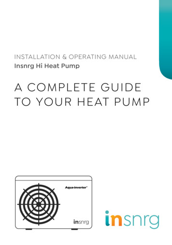
DESIGN1283699741151210Page 9StainlessLite Plus HP SOLBasic Appliance1. Hot water draw off (22mm compression)2. Lift up temperature & pressure relief valve95 /6 bar3. Hot water secondary return 22mm(not fitted to smaller sizes, see table 1)4. Immersion heater 1¾” BSP 3kW5. Cold feed (22mm compression)6. Solar thermostat pocket (22mm)7. Primary return (28mm)8. Primary flow (28mm)9. Dual control/Overheat stat & heat pumpthermostat pocket10. Solar coil return to panel collector (22mmcompression)11. Solar coil flow from panel (22mm compression)12. Solar thermostat pocketPart G3 loose components supplied in aseparate box’A. Combination inlet group incorporatingpressure reducing valve, strainer, check valve,balance cold take off point, expansion reliefvalve and expansion vessel connection points.B. Potable expansion vessels c/w integral wallbracketC. TundishD. Drain elbowE. Compression fittingsF. Dual control thermostat and combinedoverheat thermostat (x2)G. Two port (28mm) zone valve forprimary circuitSYSTEM DESIGN
DESIGNStainlessLite Plus HPBasic Appliance1. Hot water draw off (22mm) compression2. Lift up temperature & pressure relief valve95 /6 bar3. Hot water secondary return (22mmcompression, not fitted to smaller sizes,see table 2)4. Primary flow (28mm plain pipe)5. HP control thermostat6. Primary return (28mm plain pipe)7. Cold feed (22mm compression)8. Immersion heater 1¾” BSP 3kW9. Dual control/Overheat statPart G3 loose components supplied in aseparate box’A. Combination inlet group incorporatingpressure reducing valve, strainer, check valve,balance cold take off point, expansion reliefvalve and expansion vessel connection points.B. Potable expansion vessels c/w integral wallbracketC. TundishD. Drain elbowE. Compression fittingsF. Dual control thermostat and combinedoverheat thermostatG. Two port (28mm) zone valve forprimary circuitH. Thermistor cable clampSYSTEM DESIGNPage 10
DESIGNStainlessLite Plus HP SlimlineBasic Appliance1. Hot water draw off (22mm compression)2. Lift up temperature & pressure relief valve95 /6 bar3. Hot water secondar y return (22mmcompression, 210 litre model only)4. Immersion heater 1¾” BSP 3kW5. Cold feed (22mm compression)6. Primary return (28mm)7. Primary flow (28mm)8. Dual control/Overheat stat9. HP control thermostatPart G3 loose components supplied in aseparate box’A. Combination inlet group incorporatingpressure reducing valve, strainer, check valve,balance cold take off point, expansion reliefvalve and expansion vessel connection points.B. Potable expansion vessels c/w integral wallbracketC. TundishD. Drain elbowE. Compression fittingsF. Dual control thermostat and combinedoverheat thermostatG. Two port (28mm) zone valve forprimary circuitH. Thermistor cable clampPage 11SYSTEM DESIGN
DESIGNGledhill Duo CylinderBasic Appliance1. Buffer vent / AAV (½” female)2. CH flow (1” compression)3. CH return (1” compression)4. Inspection port (1¾” female)5. Buffer sensor pocket (22mm dual pocket)6. Buffer HP return (1” compression)7. HP flow (1” compression)8. T&P relief valve (½” female)9. Hot supply (¾” compression)10. Secondary return (¾” compression)11. Control thermostat (22mm dual pocket)Thermistor pocket with clamp12. HP return (28mm plain pipe)13. Immersion heater (1¾” female)14. Cold feed (22mm plain pipe)15. Three port motorised valvePart G3 loose components supplied in aseparate box’A. Combination inlet group incorporatingpressure reducing valve, strainer, check valve,balance cold take off point, expansion reliefvalve and expansion vessel connection points.B. Potable expansion vessels c/w integralbracketC. TundishD. Drain elbowE. Compression fittingsD. Dual control thermostat and combinedoverheat thermostatSYSTEM DESIGNPage 12
DESIGNGledhill Duo Pre-Plumb CylinderBasic Appliance1. Buffer vent / AAV (½” female)2. CH flow (1” compression)3. CH return (1” compression)4. Inspection port (1¾” female)5. Buffer sensor pocket (22mm dual pocket)6. Hot supply (¾” compression)7. Cold feed (¾” compression)8. Secondary return (¾” compression)9. HP flow (1” compression)10. Tundish (22mm compression)11. Control thermostat (22mm dual pocket)Thermistor pocket with clamp12. HP return (1” compression)13. Immersion heater (1¾” female)14. Three port motorised valve15. Combination inlet group incorporatingpressure reducing valve, strainer, check valve,balance cold take off point, expansion reliefvalve and expansion vessel connection points16. Auto bypass17. System pressure gauge18. Filling loopPart G3 loose components supplied in aseparate box’A. Potable expansion vessels c/w integralbracketPage 13SYSTEM DESIGN
StainlessLite Plus, HP and DUO are a range of unvented hot water storage cylinders,manufactured in the latest high quality duplex stainless steel. They are designed toprovide mains pressure hot water and are supplied as a package which complies withSection G3 of the Building Regulations. The appliance is extremely well insulated usinghigh density HCFC free foam insulation with an ozone depleting potential (ODP) ofzero and a global warming potential (GWP) of 2. It is fitted with all necessary safetydevices and supplied with all the necessary control devices to make installation onsite as easy as possible.StainlessLite Plus Heat Pump (HP) SOL models:The StainlessLite Plus HP SOL is an unvented hot water storage cylinder fitted withtwo high efficiency internal primary heat exchangers especially designed for usewith heat pump systems. These two heat exchangers must be connected in parallelto the heat pump circuit when a solar thermal system is not installed, as shown in theschematic on page 16. When both heat pump and solar thermal systems are installed,the top heat exchanger is connected to the heat pump circuit and the bottom heatexchanger is connected to the solar circuit a shown in figure 2.All StainlessLite Plus HP SOL models are fitted with 3kW (230Vac, 50Hz) immersionheater for raising the temperature of the stored water to above 60 C after the heatpump heating cycle if necessary. During commissioning the actual temperaturethat the cylinder reaches when the thermostat(s) operate should be tested andadjusted so that it achieves a minimum of 60 C in order to comply with the Legionellapasteurisation requirements. The technical details of the StainlessLite Plus HP modelsare listed in table 1.Gledhill DuoThe Gledhill Duo is a range of unvented hot water storage cylinders, manufacturedin the latest high quality duplex stainless steel. They are designed to provide mainspressure hot water and are supplied as a package which complies with Section G3 ofthe Building Regulations. The appliance is extremely well insulated using high densityHCFC free foam insulation with an ozone depleting potential (ODP) of zero and a globalwarming potential (GWP) of 1. It is fitted with all necessary safety devices and suppliedwith all the necessary control devices to make installation on site as easy as possible.The Duo product is an unvented cylinder and buffer tank combined in one case. Ithas been specifically designed to work with a heat pump source of heat.The 70 litre buffer tank lowers the number of times the heat pump needs to switchon and off. This extends the life of the compressor in the heat pump. It also enables aconstant flow rate to be maintained through the heat pump heat exchanged whichpromotes its efficient operation.The buffer is fixed above the 200 or 300 litre hot water cylinder. Both of these hotwater cylinders include a 3m2 highly efficient multi-pass corrugated stainless steelheat exchanger, and an immersion heater for backup and sterilisation purposes. Themulti pass arrangement of the coil enables high flow rates to be passed through itwith low pressure losses. The immersion heater is usually controlled by the heat pumpcontrol system which determines when it needs to run based upon the parametersselected by the commissioning engineer.The product is supplied with; a full divert 3 port valve as the energy cut off and thePTRV which will prevent any overheating of the DHW cylinder; and the usual inletcontrol group and expansion cylinder components required for unvented systems.Page 14StainlessLite Plus Heat Pump (HP) andSlimline models:The StainlessLite Plus HP and Slimline cylindersunvented hot water storage cylinders fitted witha high efficiency coil. The coil has a low pressureloss due to it being a multiple pass coil whichenable high flow rates to be achieved throughit. In addition due to the coil being corrugatedthe heat transfer rate is higher than that ofplain tube coil.The cylinder has been specifically designedfor heat pump applications. It incorporatesan immersion heater at the base of the unitwhich enables pasteurisation of the water. Thisshould be done on a regular basis in line withHWA guidance.The slimline has been designed to enable it tofit into tighter locations.Important notes:1. All StainlessLite Plus HP and Duo models aresuitable for both open vented and sealedprimary systems. Minimum of 5m H 2 Oworking pressure.2. When used with a sealed primary heatingsystem, the heat pump must incorporate itsown over heat thermostat.3. StainlessLite Plus HP and Duo models mustnot be used with uncontrolled heat sourceor steam as the heat source.4. Heat pumps can normally only heat thedomestic hot water to between 45 – 50 C,therefore provision should be made toperiodically heat the cylinder to above 60 Cto prevent growth of legionella.5. The cold supply elbow c/w drain tappingmust be fitted as shown in figures 1 & 2.A flexible hose can then be connected to thedrain tapping and providing the hose runsbelow the lowest level of the cylinder, thenall the water content can be drained out bythe syphonic action.
INSTALLATIONGeneral Design ConsiderationsFor the HP models the cupboard footprint needs to be at least 650mm square for unitsup to 300 litres, 730mm for 400 litre units. For the Duo models the cupboard footprintneeds to be at least 730mm square for all units.The base chosen for the cylinder should be level and capable of supporting the weightof the unit when full of water as shown in General Data. The discharge pipework for thesafety valves must have a minimum fall of 1 : 200 from the unit to a safe discharge point. Allexposed pipework and fittings on the cylinder should be insulated, and the unit shouldNOT be fixed in a location where the contents could freeze.In new systems, pipes should be insulated to comply with building regs, the maximumpermissible heat loss is indicated in the table opposite, and labelled accordingly as follows:i. Primary circulation pipes for domestic hot water circuits should be insulatedthrough their length, subject only to practical constraints imposed by the needto penetrate joists and other structural elements.ii. All pipes connected to hot water storage vessels, including the vent pipe, shouldbe insulated for at least 1 metre from their points of connection to the cylinder (orthey should be insulated up to the point where they become concealed).In replacement systems, whenever a boiler or hot water storage vessel is replaced inan existing system, any pipes that are exposed as part of the work or are otherwiseaccessible should be insulated as recommended for new systems, or to some lesserstandard where practical constraints dictate.The pipe connecting the boiler flow to theappliance must not be less than 22mmcopper or equivalent.Insulation of pipeworkPipe outsidediameterMaximumheat Further guidance on converting heat loss limitsto insulation thickness for specific thermalconductivities is available in TIMSA “HVACguidance for achieving compliance with Part Lof the Building Regulations”.Mains Water SupplyExisting properties with a 15mm supply will besatisfactory provided the local mains pressureis good, but should be confined to singlebathroom properties. For new properties wheresimultaneous demand is required to more thanone bathroom or a bathroom and one or moreen-suites, the communication and service pipeinto the dwelling should be a minimum of 22mm(usually in the form of a 25mm MDPE supply).The optimum performance is achieved if theinlet pressure is 3 bar dynamic. However, theStainlessLite Plus will function with lower inletpressures, but this will reduce the performance.There should be a flow of at least 30 litres perminute or above available into the property.Normally StainlessLite Plus provides well inexcess of 40 litres/min in most conditions. Flowrates for ALL mains pressure systems are subjectto district pressures and system dynamic loss.Particularly on larger properties with morethan one bathroom, the pipe sizes should becalculated in accordance with BS EN 806-3:2006and BS 8558:2011.If two StainlessLite Plus HP cylinders are coupled together
having 4 elbows and length of 7m from the tundish to the point of discharge. From Table 1: Maximum resistance allowed for a straight length of 22mm copper discharge pipe (D2) from a G1/2 temperature relief valve is: 9m subtract the resistance for 4 x 22mm elbows at 0.8m each 3.2m. Therefore the maximum permitted length equates to: 5.8m.