Transcription
V-PAC inverter heat pumpsVPT 12, 16, 22Owner Installation Manual 1005759 Issue 3
OWNER/INSTALLATION MANUALHEALTH AND SAFETY WARNINGThis product contains electrical and rotationalequipment. ONLY competent trained peopleshould work on this device, and must beisolated electrically before removing accesspanels.This appliance can be used by children from8 years and above and persons with reducedphysical, sensory or mental capabilities orlack of experience and knowledge if theyhave been given supervision or instructionconcerning use of the appliance in a safe wayand understand the hazards involved. Childrenshould not play with the appliance. Cleaningand user maintenance shall not be made bychildren without supervision.HEALTH AND SAFETY WARNING21005759 ISSUE 3
CONTENTSHEALTH AND SAFETY WARNING 24.0 USING YOUR HEAT PUMP 191.0 INTRODUCTION 44.1 THE KEY PAD 191.1 FOREWORD 44.2 OPERATING INSTRUCTIONS 201.2 WARNINGS 45.0 TESTING 222.0 ABOUT YOUR HEAT PUMP 85.1 HEAT PUMP MALFUNCTION 232.1 TRANSPORTATION 85.2 PROTECTION CODES 242.2 ACCESSORIES 85.3 FAULT CODES 252.3 FEATURES 96.0 MAINTENANCE 262.4 OPERATING CONDITIONS AND RANGE 97.0 TROUBLE SHOOTING COMMON FAULTS 262.5 OPERATING MODES 98.0 DATA SHEET 273.0 INSTALLATION 109.0 DIMENSIONS 283.1 POSITIONING AND AIRFLOW 1010.0 WINTERISATION PROCEDURE 293.2 REFRIGERANT TYPE AND INSTALLEDLOCATION 1310.1 START UP PROCEDURE AFTERWINTERISATION 293.3 POOL WATER CIRCUIT 1411.0 WARRANTY CONDITIONS 303.4 PLUMBING 1512.0 DECLARATION OF CONFORMITY 313.5 INITIAL CHECKS 153.6 ELECTROLYTIC CORROSION IN SWIMMINGPOOLS 163.7 ELECTRIC WIRING AND SUPPLY 163.8 CONNECTING THE HEAT PUMP TO THEPOWER SUPPLY 173.9 POOL PUMP OVERRIDETERMINALS P1/P2 181005759 ISSUE 33
OWNER/INSTALLATION MANUAL1.0 INTRODUCTION1.1 FOREWORDThank you for choosing this product, which is designedfor quiet and energy efficient operation. It is the idealway to heat your pool in an environmentally friendlyway.This guide provides information needed to install andoperate the product effectively. Please ensure youread this manual and use the correct installation andoperating procedures.This manual is intended for installers and users.Read the entire manual before using the heatpump. Awareness of the correct operatingprocedure for the machine and any safety devicesis important, to avoid damage or injury.The appliance can be used by children aged from 8years and above and persons with reduced, physical,sensory or mental capabilities or lack of experienceand knowledge if they have been given supervisionor instruction concerning use of the appliance in a safeway and understand the hazards involved. Childrenshall not play with the appliance. Cleaning and usermaintenance shall not be made by children withoutsupervision.1.2 WARNINGSImportant safety information is contained in this manualand marked on the heat pump.Please read and follow all safety advice.The refrigerant used in this heat pump is R32.This refrigerant is environmentally friendly, butsafety instructions must be strictly adhered to.The WARNING sign denotes a hazard. It callsattention to a procedure or practice, which if notadhered to could result in injury. Warning signsand procedures must be complied with.If a refrigerant leak is suspected stop using theheat pump and contact Dantherm Group UKservice.service.department@dantherm.comTake the following precautions in order to avoidany danger:REFRIGERANT SAFETY:This heat pump contains R32 refrigerant. Workon the refrigeration system, repair and disposalmust be carried out by appropriately qualified andregistered engineers.Repair, service and disposal must be carried out in theEU by F-Gas registered engineers.Completely de-gas the refrigerant before any brazingis performed. Brazing can only be carried out bytechnicians trained to EU 517/2014.Risk assessments must be carried out beforemaintenance or repairs are started.Appropriate safety measures and risk assessmentsmust be taken before work commences.Do not attempt to work on the equipment byyourself.Consult the qualified engineer undertaking the work toestablish all requirements before work commences.41005759 ISSUE 3
ACTIONS TO AVOID (OPERATION ANDHANDLING):Do not use or store combustible gas or liquids near theheat pump.Be especially careful when handling the heat pump,not to cause any damage that may result in leakage ofthe cooling circuit.Check if there are any local regulations, whichyou must comply to, when installing or storingthe heat pump.Do not use means to accelerate the defrosting processor to clean, other than those recommended by themanufacturer.Be aware that refrigerants may not contain anodour.Do not pierce or burn.IN CASE OF FIRE:Toxic fumes may occur in the event of fire. You mustleave the room as quickly as possible in the event offire.LOCATION REQUIREMENTS:The heat pump contains R32 refrigerant so thefollowing location requirements must be fulfilled:The heat pump must be kept away from sources of fireor naked flames.The heat pump must be installed, operated andstored where the floor area is larger than the minimumrequirement., see section 3.2.The heat pump shall be stored in a room withoutcontinuously operating ignition sources (for example:open flames, an operating gas appliance or anoperating electric heater).Keep the ventilation openings clear of obstructionduring operation.1005759 ISSUE 35
OWNER/INSTALLATION MANUALInstallation must be carried out by competent people,in accordance with this manual.INSTALLATION:Read the instructions before installation, use andmaintenance.If R32 gas leaks during the installation process, stop theinstallation immediately and call the service centre.If a repair is required, please contact the nearest aftersales service centre.To avoid over heating or over cooling of pool watercheck and set the temperature on the control panel.The heating performance can be improved byinsulating the flow and return pipework.It is recommended that a cover is used on theswimming pool to reduce heat losses.AIRFLOW:HEAT PUMP MALFUNCTION:WARNING: Isolate heat pump electrically and wait3 minutes before removing panels or entering heatpump.Refer to the user check list in section 6.2 and the errorcodes listed in section 6.3 before initiating a service call.Do not attempt to interfere with any internal controlsettings as these have been factory calibrated andsealed.Any sign of abnormal operation such as water drippingshould be reported immediately to the installer. Ifin doubt or if advice is required contact the Servicesupport team on telephone 44(0)1621 856611(option 4).MAINTENANCE:Isolate the power supply of the heat pump and wait 3minutes before cleaning examination or repair.The heat pump must have access to adequate airflow.See section 3.1.Please clean this machine with household detergentsor clean water. NEVER use petroleum spirit, thinners orany similar fuel.Do not place obstructions that will block air flow nearthe inlet or outlet.Check bolts, cables and connections regularly.ELECTRICAL SAFETY:Mains power isolator should be out of reach of children.After a power cut, when the power supply is restored,the heat pump may start up without warning.Electric storms can damage electronic equipment.Ideally the heat pump should be switched off at themains.6DISPOSAL:Repair, service and disposal of redundant heat pumpsmust be completed by authorised technicians. It isillegal to allow refrigerant gases to escape to air.Do not attempt to work on the equipment by yourself.Improper operation may cause danger.1005759 ISSUE 3
Do not use means toaccelerate the defrostingprocess or to clean, other thanthose recommended by themanufacturer.The heat pump must be keptaway from sources of fire ornaked flames.The appliance shall be storedin a room without continuouslyoperating ignition sources(for example: open flames, anoperating gas appliance or anoperating electric heater.The heat pump must beinstalled in well ventilatedarea. Closed areas are notpermitted.Do not piece or burn.Be aware that refrigerantsmay not contain an odour.Appliance shall be installed,operated and stored in aroom with a floor area largerthan Xm2, where X is the“minimum area” shown insection 3.2 and section 8.0.1005759 ISSUE 3Repair and disposal mustbe carried out by F-Gasregistered engineers.Completely de-gas therefrigerant before any brazingis performed. Brazing can onlybe carried out by technicianstrained to EU 517/2014.7
OWNER/INSTALLATION MANUAL2.0 ABOUT YOUR HEAT PUMP2.1 TRANSPORTATIONAlways keep the heat pump upright.Do not lift the heat pump by the water inlet oroutlet connections.(If this is done the titanium heat exchanger inside theheat pump could be damaged).X2.2 ACCESSORIESThese accessories are provided with the heat pump.Water union connectors:2 x 1 ½, 2 x 50mmDrainage kit4 x rubber mounts81005759 ISSUE 3
2.3 FEATURES Stepless DC inverter compressor EEV Technology (Electronic Equalisation Valve) Quick hot gas defrosting with 4-way valve High-efficiency twisted titanium heat exchanger High pressure and low pressure protection Soft start and wide voltage application Stable inverter control system2.4 OPERATING CONDITIONS AND RANGEAir temperature operating range:V-PAC (VPT X models): -5-43 C.Water temperature setting range:Heating: 18 C-40 CCooling: 12 C-30 C2.5 OPERATING MODESThe heat pump has three modes: Powerful mode,Silent mode, and Smart mode.ModePowerfulModesPowerful modeSilentSilent modeSmartSmart mode1005759 ISSUE 3CharacteristicsHeating Capacity 100%Fastest heating, ideal for initial pool heat up.Heating Capacity 50%Quiet operation, ideal for night time operation.Heating capacity from 25% to 100%Intelligent optimization ideal for day to day operation.9
OWNER/INSTALLATION MANUAL3.0 INSTALLATIONInstallation must only be attempted by competentpersonnel.3.1 POSITIONING AND AIRFLOWAirflow - general principlesThe heat pump must be positioned in a wellventilated area. Minimum distances between the heatpump and any obstructions are shown below. The heat pump must be fixed by M10 bolts to aconcrete base or mounting brackets. These must besolid and fixed securely. Brackets must be corrosionproof.The heat pump absorbs energy from the air drawnthrough it. To function effectively the heat pump musthave access to the fresh air it needs. Air must not recirculate. The air leaving the heatpump must not be sucked back into the inlet.reduced.Important installation beinstruction Do not block inlet or outlet grilles. Air must not be restricted. The air volume must not The minimum required distances shown belowmust be provided to minimise the risk of airrecirculation or restriction and reduction inperformance. Further examples are shown on thefollowing page.3000mm500mm500mm500mm101005759 ISSUE 3
Wall 300cm 50cmWall 50cm 50cm 50cm 50cmTypical inside or plant roominstallation.(Not recommended for long ductruns).Typical outside installation.The plant room must notbe used as an occupiedspace.Required free areas to provide air flow to and from heatpumps when installed in an enclosed area or whererequired to pass air through a wall etc. Ensure holesthrough walls are sealed to avoid the outlet air enteringcavities and to avoid the possibility of recirculation.Free area is the available area through which air canpass through a grille or louvres.1005759 ISSUE 3Minimum free areas m2ModelDischarge areaVPT 120.188VPT 160.188VPT 220.22011
OWNER/INSTALLATION MANUAL 350 cmTo comply with safety regulations regarding electricalinstallations in wet areas the heat pump must beinstalled at least 350cm away from the edge of thepool or spa.Swimming pool or spa121005759 ISSUE 3
3.2 REFRIGERANT TYPE AND INSTALLEDLOCATIONThis heat pump contains R32, which is anenvironmentally friendly refrigerant with a GWP(Global Warming Potential) of 675. R32 has the safetyin use classification of A2L, being low toxicity andlower flammability. In practical terms it is very difficultto ignite an A2L refrigerant, but this classificationrequires a risk assessment to be undertaken for thepossibility of refrigerant being released by accident intoan area connected to the heat pump, considering theapplication, location of components, and the installedrefrigerant charge. This installation guidance can formthe framework for such a risk assessment for theinstallation.ModelAll flammable refrigerants will not ignite if theconcentration level in a room stays below their lowerflammability limit (LFL). European standard EN378defines requirements to remain far below the lowerflammable limit in case of accidental leakage. Bychoosing the location as dictated by EN378-1:2016the probability of forming a flammable atmospherecan be eliminated. Please refer to the minimumarea for each product and the interpretation belowregarding locations of heat pump and swimming pool.This information is provided as a guide only and doesnot supersede the regulations or health and rantchargeR32 kg0.80.81.7Minimum aream²5.45.424.6Notes*Assumed worst case for access category: a - general access and locationclass: I - mechanical equipment in occupied space; both as defined in line withEN378-1 2016 section 5.1 table 4 and section 5.3*Minimum Area is calculated in line with section C.2 on EN378-1 2016(calculation C.2).INTERPRETATIONPlease refer to the installation situations below for howto apply the minimum area stated above.Pool inside and heat pump outside:The pool hall must exceed the minimum arearequirement shown above.Pool outside and heat pump outside:Automatically meets the minimum area requirementbecause outside space is unlimited.Pool inside and heat pump inside a plant room,isolated from the pool hall:The pool hall must exceed the minimum arearequirement shown above.Pool outside and heat pump inside a plant room:Automatically meets the minimum area requirementbecause the room must open to the outside for heatpump airflow and the outside space is unlimited.Pool inside and heat pump inside a plant room,ventilated to the pool hall:The pool hall and plant room combined must exceedthe minimum area requirement shown above.1005759 ISSUE 313
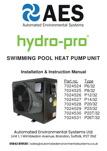
OWNER/INSTALLATION MANUAL3.3 POOL WATER CIRCUITPoolAux heater(If fitted)Non returnvalveSanitiser orchemical dosingdevice,(If fitted)Anti return loopto be incorporated,minimum height100mm aboveheat pumpoutlet port(If sanitiser fitted)100mmCalorexHeat pumpCondensatewater towasteTo wasteforwinterisingdrain downTo wasteSpare portBypassfor winterisingvalveflushing(adjusted olation valveBreakable couplingThree way valve141005759 ISSUE 3
3.4 PLUMBINGIMPORTANTBefore installing the heat pump ensure theblanking disks are removed from the pool waterin/out connections. These should drop out whenthe adaptors are unscrewed.Supported pipework1. Ensure that bypass is installed and set to achievethe recommended flow rates stated in the datasheet.2. Ensure that the condensate drain kit supplied isfixed and is drained to a drain or soak-away.3.5 INITIAL CHECKSWateroutWaterinStart the filtration pump before the heat pump isturned on and turn off the heat pump before thefiltration pump. It is recommended to turn off the heatpump prior to backwashing.Before starting the heat pump, please check forany leakage of water; and check/set the requiredtemperature on the controller, and then turn on.3. Inlet and outlet pipework must be supported toavoid excessive strain on the connections.4. Water quality must be maintained. See warrantyconditions.In order to protect the components, the heat pumpincorporates time delays. When starting heating/coolingthe fan will run for one minute before the compressorstarts. The heat pump runs for a minimum of 5minutes. When the heat pump stops heating/cooling,or is turned off by the user, the fan will continue to runfor one minute.After starting up, check for any error codes or abnormalnoise from the heat pump.1005759 ISSUE 315
OWNER/INSTALLATION MANUAL3.6 ELECTROLYTIC CORROSION IN SWIMMINGPOOLSElectrolytic corrosion will occur when dissimilar metalsthat are in contact with each other create a potentialdifference between themselves. Sometimes separatedby a conductive substance known as an electrolyte, thedissimilar metals will create a small voltage (potentialdifference) that allows the ions of one material to passto the other.Just like a battery, ions will pass from the most positivematerial to the more negative material.Anything more than 0.3 volts can cause the mostpositive material to degrade.A swimming pool with its associated equipmentcan create this effect. The pool water being an idealelectrolyte and components of the filtration circuit,heating system, steps, lights etc providing the dissimilarmetals needed to complete the circuit.Whilst these small voltages are rarely a safety threat,they can create premature failure through corrosion.Not dissimilar to corrosion through oxidation, electrolyticcorrosion can cause complete failure of a metallicmaterial in a very short period of time.In order to prevent this type of corrosion all metalliccomponents in contact with swimming pool watershould be bonded together using 10mm² bondingcable. This includes non-electrical items such as metalfilters, pump strainer boxes, heat exchangers, stepsand handrails. It is highly recommended that bondingbe retrofitted to existing pools, which may not beprotected by this system.163.7 ELECTRIC WIRING AND SUPPLYAll electrical work to be carried out in accordance withl.E.E.regulations, latest issue, or local codes of practiceas applicable. .The machine should be installed in accordance withEMC2004/108/EC.Always isolate the main ower supply before removingmachine covers.The machine power supply must incorporate thefollowing. Fuses or motor type circuit breakers (aMFuse / MCB type C) to specified rating (see datasheet).When using a fuse, H.R.C. fuses are recommended. Anisolator which disconnects all poles must be must fittedwithin 2m and in line of sight of the heat pump. Theisolator must have a minimum of 3mm air gap whenturned off.All units must be correctly earthed/grounded and itsown separate type F RCD earth leakage trip installedwhich protects the machine only.The following limits of operation must not be exceeded.Failure to provide the necessary voltages will invalidatethe warranty. This voltage must be available at the heatpump whilst running. The voltage must not drop belowthe above figures when starting the compressor.MinimumMaximum207V253VVoltageSingle phase machinesCycle frequency (50Hz) 47.5Hz52.5Hz1005759 ISSUE 3
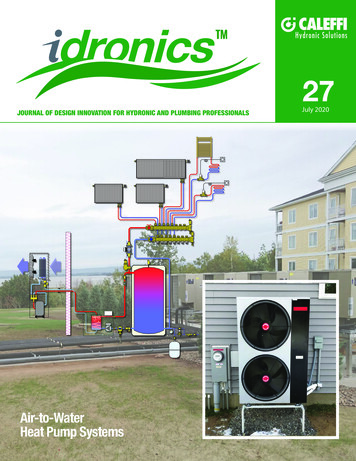
3.8 CONNECTING THE HEAT PUMP TO THE POWERSUPPLYCable Entry pointPosition of terminalsSingle phaseTerminals in Heat Pump Electrics enclosurePowerterminalsPumpterminalsL NP1 P2Cable clampSupplycordSecure cablesusing cable clampsand feed throughcable entry points inmachineIsolator whichdisconnects all polesfitted within 2m and in lineof sight of the heat pumpIsolator whichdisconnects all polesfitted within 2m and in lineof sight of the heat pumpFuse/MCBRCD/CircuitBreakerLNDistribution boxEarthed PowerSupply 230V 50Hz1005759 ISSUE 317
OWNER/INSTALLATION MANUAL3.9 POOL PUMP OVERRIDETERMINALS P1/P2For installations where the pool filter pump runscontinuously, these terminals do not need to be used.For installations where a timeclock controls the poolfilter pump, and the same pump provides water flowto the heat pump, the heat pump can override “pumpoff” periods to ensure the pool is heated/cooled. Toactivate this setting please speak to your installer.This feature operates by over-riding the timeclockwhenever the controller measures a water temperaturethat needs heating/cooling. If the pool does not needheating/cooling the filter pump will be turned off untilthe controller next measures a water temperaturethat needs heating/cooling. If the pool needs heating/cooling the heat pump will continue to run the filterpump and heat/cool the pool.When installed in parallel with the timeclock, the poolfilter pump will run when:This feature will reduce the pool filter pump run time tominimise pump energy usage.a) a period of “pump on” has been set on the timeclock for filtration purposes.b) a period of “pump off” has been set in the timeclock and the heat pump runs the pool filter pump fortemperature sampling and if the pool subsequentlyrequires heating/cooling.Terminals inheat pumpP1Customer’s external pump/filter time clockSeparate supplyLNEFuseLRelayP2230V coilPool pumpstarterNLSingle phasewater pump18N1005759 ISSUE 3
4.0 USING YOUR HEAT PUMP4.1 THE KEY PADModeDownUp88.88LED displayHeating indicator lightM Powerful SmartHEATCOOLTimer on indicator lightTimer off indicator lightCooling indicator lightPowerSilentSilent mode indicator lightSmart mode indicator lightPowerful mode indicator lightNote: When the heat pump is powered off, the displayshows the time.18.05MPowerful1005759 ISSUE 3 Smart HEATCOOLSilent19
OWNER/INSTALLATION MANUAL4.2 OPERATING INSTRUCTIONSIMPORTANTRemember that at startup there is a 1 minute time delay before the heat pump startsa. Power on.e. DefrostingPressto power the unit on or off. Note. a shortpress will return the controller to main menu.1. Automatic defrosting. When machine is defrostingthe heating indicator lamp flashes; after defrosting theflashing stops.b. Temperature setting.Press p and q to display and adjust the settemperature. Pressto save settings and return tomain screen.c. Mode SelectionPress M to enter mode.PowerfulPowerful mode indicator lamp lit.SmartSmart mode indicator lamp litSilentSilent mode indicator lamp litd. Heat mode selection2. Forced Defrosting. When machine is heating andthe compressor has been running continuously for 10minutes. Press p and q together for 5 seconds. theheating mode lamp flashes and defrost starts. Whendefrosting is exited the display returns to normal.f. Clock SettingTurn the heat pump off via the. Press M toenter the clock settings. Press M and the hourflashes. Using the p and q set the hour. Press Magain to make the minutes flash and use the p andq to set. Press the M once more to return to themain display. Press theto turn the heat pumpsback on.Press M to switch between heating and cooling.Heating Heating indicator lamp lit and H on display.Cooling Cooling indicator lamp lit and C on display.201005759 ISSUE 3
g. Timer SettingPress and hold thefor 5 seconds to enter timermenu. It will now show the ‘timer on’ time. Press Mand the hour flashes. Use p and q to set the hour.Press M again and the minutes flash. Use the pand q to adjust these. Press M again to and it willnow show the ‘timer off’ time. Adjust these in thesame way as the ‘timer on’. Once complete press Mto save the setting.h. Cancel timerThere are two ways to cancel the timer settings.1. Both the timer on and timer off are set to the sametime.2. When in the interface for timer settings press andhold for 5 seconds theto cancel each timeindividually. Note. must cancel ‘Timer off’ before ‘timeron’.1005759 ISSUE 321
OWNER/INSTALLATION MANUAL5.0 TESTINGInspect heat pump before use Check that the fan, air inlets and outlets are notobstructed. It is prohibited to install refrigeration pipe orcomponents in corrosive environment. Check that the electric wiring conforms to theelectric wiring diagram and that the machine isearthed. Double check that the main power switch is off. Check the temperature setting.a. Machine diagnostics.b. Factory resetTo aid machine diagnosis the heat pump can report onsome conditions. These are shown in the table below.To access these readings press and hold the Silentfor 5 seconds, and use the p and q to scroll through.The first number that is flashing is the parameter code.Pressto return to main menu.Press and hold the Silentandtogether for 5seconds. this enters the customer parameter menu.Press and hold the Silentandtogether for 5seconds again and the reset is done. The buzzer willsound twice and all parameter values will change backto their default values.QUERY CODEMEANINGRANGE1Water inlet temperature-20 99 C2Water outlet temperature-20 99 C3Ambient temperature-20 99 C4Compressor exhaust gas temperature0 125 C5Compressor suction gas temperature-20 99 C6Evaporator coil temperature-20 99 C7Condenser coil temperature-20 99 C8 to 1422Ignored1005759 ISSUE 3
5.1 HEAT PUMP MALFUNCTIONWARNING: Isolate heat pump electrically, andwait 3 minutes before removing panels orentering heat pump. Refer to the user check list in section 5.2 and theerror codes listed in section 5.3 before initiating aservice call. Do not attempt to interfere with any internalcontrol settings as these have been factorycalibrated and sealed.FaultHeat pump doesn’t runFan running but with insufficientheatingDisplay normal, but no heating Any sign of abnormal operation such as waterdripping should be reported immediately tothe installer. If in doubt or if advice is requiredcontact the Service support team on telephone 44(0)1621 856611 (option 4).ReasonSolutionNo powerWait until the power is restoredPower is switched offSwitch on the powerFuse has blownCheck and change the fuseThe breaker is offCheck and turn on the breakerEvaporator blockedRemove the obstructionsAir outlet blockedRemove the obstructions3 minutes start delayWait for the delay timer to time outSet temperature too lowSet desired heating temperature3 minutes start delayWait for the delay timer to time outInaccurate switch action.Stop the machine, and cut off the power supply immediately, thenThe fuse blows frequently orcontact your dealerleakage circuit breaker tripsfrequentlyIf above solutions don’t work, please contact your installer with detailed information and your model number.Don’t try to repair it yourself.1005759 ISSUE 323
OWNER/INSTALLATION MANUAL5.2 PROTECTION CODESThese codes indicate machine stopping due to externalcircumstances. These are not faults with the heatpump.NO.DisplayReasonSolution1Er 03No water flow through the heat pump.Check water circuit and pool pump.2Er 04Frost protection. The heat pump runs in heating modefor a short time when in standby mode to preventfrost build up. This does not replace winterisation.Heat pump will resume standbyonce process is completed.3Er 21Ambient temperature is out of range, either lowerthan -5 C or higher than 43 C.If outside, wait for ambientconditions to improve (winterisationmay be required). If installed ina sheltered place, check for airrecirculation.4Er 27The temperature difference between inlet and outletwater is more than 10 CCheck water flow and pool pump.241005759 ISSUE 3
5.3 FAULT CODESWhen the heat pump displays any of these faultcodes please contact your installer for advice.DisplayDescription of fault codeEr 05High pressure alarmEr 06Low pressure alarmEr 09Controller communication failureEr 10Inverter module communication errorEr 12High exhaust gas temperature alarmEr 15Water inlet temperature sensor failureEr 16Evaporator coil temperature sensor failureEr 18Exhaust gas temperature sensor failureEr 19DC fan motor errorEr 20Inverter module abnormal error protectionEr 23Low outlet water temperature protection under cooling modeEr 29Compressor suction gas temperature alarmEr 32Hight outlet water temperature protection under heat modeEr 35Compressor high current protectionEr 42Condenser coil temperature sensor failure1005759 ISSUE 325
OWNER/INSTALLATION MANUAL6.0 MAINTENANCE7.0 TROUBLE SHOOTING COMMON FAULTSIsolate the powersupply of theheat pump andwait 3 Minutesbefore cleaning,examination orrepair.Cover the heat pump body when not in use.Requirements for service personnelPlease clean this heat pump with householddetergents or clean water, NEVER use petroleum spirit,thinners or any similar fuel.Any person who is involved with working on orbreaking into a refrigerant circuit should hold a currentvalid certificate from an industry-accredited assessmentauthority, F-Gas registered.Check bolts, cables and connections regularly.Repair, service and disposal of redundant heat pumpsmust be completed by authorised technicians. It isillegal to allow refrigerant gases to escape to air.Do not attempt to work on the equipment byyourself.Do not attempt to work on the equipment by yourself.Improper operation may cause danger.261005759 ISSUE 3
8.0 DATA SHEETMODELUNITSVPT 12ALXVPT 16ALXVPT PERFORMANCE - Air 27 C Water 27 C RH 80%Heating capacityCOP RangeAverage COP at 50% SpeedPERFORMANCE - Air 15 C Water 26 C RH 70%Heating capacitykWCOP RangeAverage
2 0 ABOUT YOUR HEAT PUMP 2 1 TRANSPORTATION Always keep the heat pump upright. Do not lift the heat pump by the water inlet or outlet connections. (If this is done the titanium heat exchanger inside the heat pump could be damaged). 2 2 ACCESSORIES These accessories are provided with the heat pump. Water union connectors: 2 x 1 ½, 2 x 50mm


![Welcome [s3-ap-southeast-2.amazonaws ]](/img/28/wmi5140-user-manual.jpg)