Transcription
Swimming Pool Heat PumpUser and Service manualEnglish French Dutch German Russian Polish
INDEX FOR DIFFERENT LANGUAGESEnglish manual . 1 27Manuel français . . .28 54Nederlandse handleiding . 55 81Bedienungsanleitung Deutsch .82 108инструкцию на русском .109 135Polskiej firmy . .136 162
HYDRO-PRO Swimming Pool Heat PumpUser and Service imensionInstallation and connectionAccessoriesElectrical WiringDisplay Controller OperationRunning data settingTroubleshootingExploded DiagramMaintenanceWarranty and returnsThank you for using HYDRO-PRO swimming pool heat pump for your pool heating, it will heat your poolwater and keep the constant temperature when the air ambient temperature is at -5 to 43 ATTENTION: This manual includes all the necessary information with the use and theinstallation of your heat pump.The installator must read the manual and attentively follow the instructions in implementation andmaintenance.The installator is responsible for the installation of the product and should follow all the instructions of themanufacturer and the regulations in application. Incorrect installation against the manual implies theexclusion of the entire guarantee.The manufacturer declines any responsibility for the damage caused with the people, objects and of theerrors due to the installation that disobey the manual guidline. Any use that is without conformity at theorigin of its manufacturing will be regarded as dangerous.WARNING: Please always empty the water in heat pump during winter time or when the ambienttemperature drops below 0 , or else the Titanium exchanger will be damaged because of being frozen, insuch case, your warranty will be lost.WARNING: Please always cut the power supply if you want to open the cabinet to reach inside the heatpump, because there is high voltage electricity inside.WARNING: Please well keep the display controller in a dry area, or well close the insulation cover toprotect the display controller from being damaged by humidility.-1-
1. Specifications1.1 Technical data Hydro-Pro heat pumpsUnit 0120140A4,14,779,111,4156,67,7Maximum currentA4,95,68,41113,7188,410COP at A27/W27W/W5,85,96,266,15,95,95,8COP at A15/W26W/W44,24,44,44,34,24,24,2Power supplyV/Ph/HzPart numberHeating capacityA27/W27Heating capacityA15/W26Cooling capacityA35/W27Power inputMaximumvolume(goodinsulation)Running currentModel2222T7008321 lectronicCondenserCompressorquantityCompressor typeTitanium heat exchanger1RotaryScrollRefrigerantR410aFan quantity1Fan power inputWFan speedRPM688080120200400400400830 870Air FlowHorizontalVerticalNoise level (10m)dB(A)3940404344474750Noise level (1m)dB(A)4849495253565659Water connectionmmNominal ure 1000*360*620 01120*380*660 1165*430*995885*740*1050Kg36/38Net dimensionsShippingdimensionsNet/gross weight5044/4749/52* Above data are subjects to modification without notice.-2-63/67100/110125/135 125/135150/160
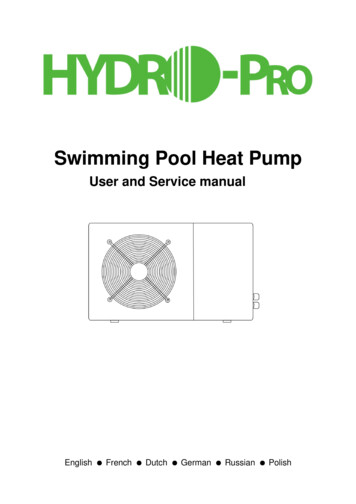
2. 0560G83838383H470520590820Unit : mmModel Hydro Pro 22, 22T, 26T-3-
3. Installation and connection3.1 NotesThe factory supplies only the heat pump. All other components, including a bypass if necessary, must beprovided by the user or the installer.Attention:Please observe the following rules when installing the heat pump:1. Any addition of chemicals must take place in the piping located downstream from the heat pump.2. Install a bypass if the water flow from the swimming pool pump is more than 20% greater than theallowable flow through the heat exchanger of the heat pump.3. Install the heat pump above the water level of the swimming pool.4. Always place the heat pump on a solid foundation and use the included rubber mounts to avoidvibration and noise.5. Always hold the heat pump upright. If the unit has been held at an angle, wait at least 24 hoursbefore starting the heat pump.3.2 Heat pump locationThe unit will work properly in any desired location as long as the following three items are present:1. Fresh air–2. Electricity–3. Swimming pool filtersThe unit may be installed in virtually any outdoor location as long as the specified minimum distances toother objects are maintained (see drawing below). Please consult your installer for installation with anindoor pool. Installation in a windy location does not present any problem at all, unlike the situation with agas heater (including pilot flame problems).ATTENTION: Never install the unit in a closed room with a limited air volume in which the air expelled fromthe unit will be reused, or close to shrubbery that could block the air inlet. Such locations impair thecontinuous supply of fresh air, resulting in reduced efficiency and possibly preventing sufficient heat output.See the drawing below for minimum dimensions.-4-
3.3 Distance from your swimming poolThe heat pump is normally installed within a perimeter area extending 7.5 m from the swimming pool. Thegreater the distance from the pool, the greater the heat loss in the pipes. As the pipes are mostlyunderground, the heat loss is low for distances up to 30 m (15 m from and to the pump; 30 m in total)unless the ground is wet or the groundwater level is high. A rough estimate of the heat loss per 30 m is0.6 kWh (2,000 BTU) for every 5 ºC difference between the water temperature in the pool and thetemperature of the soil surrounding the pipe. This increases the operating time by 3% to 5%.3.4 Check-valve installationNote: If automatic dosing equipment for chlorine and acidity (pH) is used, it is essential to protect the heatpump against excessively high chemical concentrations which may corrode the heat exchanger. For thisreason, equipment of this sort must always be fitted in the piping on the downstream side of the heatpump, and it is recommended to install a check-valve to prevent reverse flow in the absence of watercirculation.Damage to the heat pump caused by failure to observe this instruction is not covered by the warranty.-5-
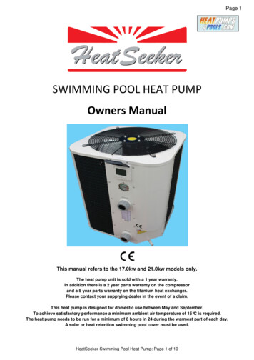
3.5 Typical arrangementNote: This arrangement is only an illustrative example.3.6 Adjusting the bypassUse the following procedure to adjust thebypass: fully open all three valves slowly close valve 1 until thewater pressure is increased byTo poolFrom poolapproximately 100 to 200 g Close valve 3 approximatelyhalf-way to adjust the gaspressure in the cooling system OutInIf the display shows "ON" orerror code EE3, close step bystep the valve 2, to increasewater flow and stop when thecode disappear.Heat PumpOptimal operation of the heat pump occurs when the cooling gas pressure is 22 2 bar.This pressure can be read on the pressure gauge next to the control heat pump panel. Under theseconditions the water flow through the unit is also optimal.Note: Operation without a bypass or with improper bypass adjustment may result in sub-optimalheat pump operation and possibly damage to the heat pump, which renders the warranty null andvoid.-6-
3.7 Electrical connectionNote: Although the heat pump is electrically isolated from the rest of the swimming pool system,this only prevents the flow of electrical current to or from the water in the pool. Earthing is stillrequired for protection against short-circuits inside the unit. Always provide a good earthconnection.Before connecting the unit, verify that the supply voltage matches the operating voltage of the heat pump.It is recommended to connect the heat pump to a circuit with its own fuse or circuit breaker (slow type;curve D) and to use adequate wiring (see table below).For horizontal models (Hydro Pro7, 10, 13 and 18): remove the panel to the right of the fan opening.(Hydro Pro 5: remove the top panel).For vertical models (Hydro-Pro22, 22T and 26T): remove the corner panel with the electronic control panel.Connect the electrical wires to the terminal block marked ‘ POWER SUPPLY ’.A second terminal block marked ‘WATER PUMP ’ is located next to the first one. The filter pump (max. 5 A /240 V) can be connected to the second terminal block here. This allows the filter pump operation to becontrolled by the heat pump.Note: In the case of three-phase models, swapping two phases may cause the electric motors to run in thereverse direction, which can lead to damage. For this reason, the unit has a built-in protective device thatbreaks the circuit if the connection is not correct. If the red LED above this safety device lights up, youmust swap the connections of two of the phase wires.ModelHYDRO PRO7HYDRO PRO10HYDRO PRO13HYDRO PRO18HYDRO PRO22HYDRO PRO22THYDRO PRO26TVoltage (V)220–240220–240220–240220–240220–2403x 3803x 380Fuse orcircuitbreaker (A)16162025322020-7-Rated current (A)Wire diameter mm2(with max. 15 m length)6.69.212.116.520.97.98.92x 1.5 1.52x 2.5 2.52x 2.5 2.52x 6 62x 6 64x 2.5 2.54x 2.5 2.5
3.8 Initial operationNote: In order to heat the water in the pool (or hot tub), the filter pump must be running to cause thewater to circulate through the heat pump. The heat pump will not start up if the water is notcirculating.After all connections have been made and checked, carry out the following procedure:1. Switch on the filter pump. Check for leaks and verify that water is flowing from and to the swimmingpool.2. Connect power to the heat pump and press the On/Off buttonon the electronic control panel. Theunit will start up after the time delay expires (see below).3. After a few minutes, check whether the air blowing out of the unit is cooler.4. When turn off the filter pump , the unit should also turn off automatically , if not, then adjust the flowswitch.5. Allow the heat pump and the filter pump to run 24 hours a day until the desired water temperature isreached. The heat pump will stop running at this point. After this, it will restart automatically (as long asthe filter pump is running) whenever the swimming pool water temperature drops 2 degree below theset temperature.Depending on the initial temperature of the water in the swimming pool and the air temperature, it may takeseveral days to heat the water to the desired temperature. A good swimming pool cover can dramaticallyreduce the required length of time.Water Flow Switch:It is equipped with a flow switch for protecting the HP unit running with adequate water flow rate .It will turnon when the pool pump runs and shut it off when the pump shuts off. If the pool water level higher than 1m above or below the heat pump’s automatic adjustment knob, your dealer may need to adjust its initialstartup.Time delay - The heat pump has a built-in 3-minute start-up delay to protect the circuitry and avoidexcessive contact wear. The unit will restart automatically after this time delay expires. Even a brief powerinterruption will trigger this time delay and prevent the unit from restarting immediately. Additional powerinterruptions during this delay period do not affect the 3-minute duration of the delay.3.9 CondensationThe air drawn into the heat pump is strongly cooled by the operation of the heat pump for heating the poolwater, which may cause condensation on the fins of the evaporator. The amount of condensation may beas much as several litres per hour at high relative humidity. This is sometimes mistakenly regarded as awater leak.-8-
4. Accessories4.1 Accessories listAnti-vibration base, 4 pcs10M Signal wire, 1 pcDraining jet, 2 pcsWaterproof box, 1 pcWater connection assembly, 2 sets4.2 Accessories InstallationAnti-vibration bases1. Take out 4 Anti-vibrationbases2. Put them one by one on thebottom of machine like thepicture.Draining jet1. Install the draining jet underthe bottom panel2. Connect with a water pipe todrain out the water.Note: Lift the heat pump toinstall the jet. Never overturn theheat pump, it could damage thecompressor.-9-
Water Inlet & outlet junction1. Use the pipe tape to connectthe water Inlet & outlet junctiononto the heat pump2. Install the two joints like thepicture shows3. Screw them onto the waterInlet & outlet junction10M Signal wiring1. Take one side of the 10MSignal wire, to connect with thecontroller.2. The other side needs to bepulled through the hole, like thethird picture shows.3. Then connect to the PC boardinside the machine : the brownone --- first joint; the blue one --second joint; the yellow one --third joint.Cable wiring1. Connect the power supplywire through the white hole likethe picture shows.2. Fix the other side on jointsinside the electric box.- 10 -
Water pump wiring1. Connect the water pump wirethrough the white hole marked2. Fix the other side on jointsinside the electric box.5. Electrical Wiring5.1 SWIMMING POOL HEAT PUMP WIRING DIADRAHydro Pro 5/7/10- 11 -
5.2 SWIMMING POOL HEAT PUMP WIRING DIADRAHydro Pro 13- 12 -
5.3 SWIMMING POOL HEAT PUMP WIRING DIADRAHydro Pro 18/22- 13 -
5.4 SWIMMING POOL HEAT PUMP WIRING DIADRAHydro Pro 22T/26TNOTE:(1)Above electrical wiring diagram only for your reference, please subject machine posted the wiringdiagram.(2)The swimming pool heat pump must be connected ground wire well, although the unit heat exchanger iselectrically isolated from the rest of the unit .Grounding the unit is still required to protect you against shortcircuits inside the unit .Bonding is also required.Disconnect: A disconnect means (circuit breaker, fused or un-fused switch) should be located within sightof and readily accessible from the unit .This is common practice on commercial and residential heat pumps.It prevents remotely-energizing unattended equipment and permits turning off power at the unit while theunit is being serviced.- 14 -
5.5 Installation of the display deporteePhoto (1)Photo (2)Photo (3)- Disassembling of and degrafage control board of the connector (photo1)- Installation of the provided cable (photo 2)- To pass the cable by the press pack (photo 3) and to connect the sons directly6. Display Controller Operation6.1 The buttons of LED wire controllerWhen the heat pump is running, the LED display shows the inlet water temperature.When the heat pump is standby, the LED display shows the real time.6.2 Start or stop the heat pump.Pressto start the heat pump unit, the LED display shows the desired water temperature for 5 seconds,then shows the inlet water temperature.Pressto stop the heat pump unit.6.3 Choose heating or cooling mode:- 15 -
Pressuntil “heat” or “Cool” light is on.6.4 Setting the real timeOn standby or running mode, long presshour/minute.Then press theWhen setting the time,for 10 seconds, then pressorto adjustagain to store the new data.andcannot work.6.5 Water temperature setting:On standby or running mode, pressandto adjust the desired water temperatureNote : the heat pump can running only if the water circle/filtration system is running.6.6 Automatic start/stop the heat pumpTo set the time to start the unitPressto set the time to start the unit, then pressorto adjust the time (set the time fororto adjust the time (set the time forstart5 minutes after the water pump).again to store the new data.PressTo set the time to stop the unitPressto set the time to stop running, then pressstop5 minutes before the water pump).Pressagain to store the new data.6.7 Concell the automatic start/stopTo concell the automatic starter, then press,PressTo concell the automatic starterPress,then presslight off and the automatic start is off.,light off and the automatic stop is off.- 16 -
Note : If the water filtration system is stop before the heat pump, the unit will shut down (securitycondition) and the code EE3 or ON advertise on the controller.It is important to program the heat pump link the time program of the water filtration system.For restart the heat pump, turn off and turn on the electrical power supply to restart the unit.7. Running data setting7.1 How to check the parametersOn standby or running mode, long pressfor 10 seconds, then pressparameters (from 0 to H, see operation parameter table).orto check the7.2 How to adjust the parameters (Can only adjust on standby mode)for 10 seconds, press1) Long pressparameter table) you want to adjust.again to select the data (from 0 to L, see operation2) Then pressorto adjust the parameter, press3) Then pressorselect the other datas you want to adjust, repeat above operation.- 17 -again to store the new data.
Please kindly noted:A) Press “MODE” to choose mode (Mode only be changed for “1” or “2” setting of parameter 6)B) Mode can be changed while runningC) Auxiliary electrical heating is not applicable to these modes.7.3 How to know the current status- 18 -
- 19 -
Parameter01MeaningTo set the entering water temp.under cooling modeTo set the entering water temp.under heating modeRangeDefaultRemarks8-35 28 Adjustable15-40 28 Adjustable2Entry into defrosting time period30-90MIN40MINAdjustable3Terms of Entry defrosting function-30 to0 -7 Adjustable45Terms of Exit defrosting2 to 30 13 Adjustable1 to 12MIN12MINAdjustable0-31(Heat and Cool)Adjustable0-11(auto)AdjustableSuperheat for heating target-15 -15 3 AdjustableSuperheat for cooling target-15 -15 -2 Adjustable18-9470AdjustableTime of Exit defrostingMode: 0 Cool 1 Heat and Cool 26Heat and cool auxiliary elec.Heating 3 Heat789ABCDEFGHLMode selection of Electronicexpansion valveManual adjustment steps ofelectronic expansion valveInlet water temperature-9-99 Exact testing by valueOutlet water temperature-9-99 Exact testing by value-9-99 Exact testing by valueGas return temperature-9-99 Exact testing by valueAmbient temperature-9-99 Exact testing by value-9-99 Exact testing by valueN*5Exact testing by valueCondenser temperature underheating modeCondenser temperature underCooling modeActual steps of electronicexpansion valveEntering water temperaturecalibration-9.9-9.9 0 AdjustableRemarks:(1) When HP stop running in 30 seconds, water pump will shut off automatically(2) LED wire controller can operate the water pump after connected additional cable to the pump device inthe position of “PUMP” terminal accurately.(3) It is necessary to put an extra 3-phase transfer device for 3 phase water pump.- 20 -
8. Troubleshooting8.1 Error code display on LED wire controllerMalfunctionInlet water temperatureError codePP1sensor failureOutlet water temperaturePP2The sensor in open or shortCheck or change the sensorThe sensor in open or shortCheck or change the sensorcircuitPP3failureGas return sensor failureSolutioncircuitsensor failureHeating condenser sensorReasonThe sensor in open or shortCheck or change the sensorcircuitPP4The sensor in open or shortCheck or change the sensorcircuitAmbient temperaturePP5sensor failureTemperature differenceThe sensor in open or shortCheck or change the sensorcircuitWater flow volume notCheck the water flow volume orbetween water inlet andenough ,water pressurewater jammed or notoutlet is too muchdifference is too lowCooling outlet waterPP6PP7temperature is too lowFirst grade antifreezePP7protection in WinterWaterflowvolumeisnotCheck the water flow or waterenoughsystem is jammed or notAmbient temperature or waterWaterinlet temperature is too Second grade antifreezePP7protection in WinterCooling condenser sensorPP8failureHigh pressure protectionAmbient temperature or waterHeat pump will start heating forinlet temperature is too lowsecond grade antifreezeThe sensor in open or shortCheck or change the sensorcircuitEE11. Refrigerant is too much2. Air flow is not enough1. Discharge redundantrefrigerant from HP gassystem2. Clean the air exchangerLow pressure protectionEE21. Refrigerant is not enough1. Check if there is any gas2. Water flow is not enoughleakage ,re-fill the refrigerant3. Filter jammed or capillaryjammedFlow switch closedEE3 or "ON"2. Clean the air exchanger3. Replace the filter or capillaryLow water flow, wrong flowCheck if the water flow is enoughdirection, or flow switch failure.and flow in right direction, or elsethe flow switch could be failed.Power supply connectionsEE4Wrong connection or lack ofCheck the connection of powerconnectioncableWater flow volume is notCheck the water flow rate ,ortemperature differenceenough ,water pressurewater system is jammed or notmalfunctiondifference is too lowwrong (for 3 phase unit)Inlet and outlet waterCommunication failureEE5EE8Wire connection is not good- 21 -Check the wire connection
8.2 Other Malfunctions and Solutions (No display on LED wire controller)MalfunctionsObservingLED wire controllerno display.No power supplyLED wire controller.Heat pump under standbydisplays the actual time.statusSolutionCheck cable and circuitbreaker if it is connectedStartup heat pump to run.1. Verify water temperatureHeat pump isnot runningReasons1. Water temperature issetting.LED wire controllerreaching to setting value, HP under2. Startup heat pump afterdisplays the actualconstant temperature status.a few minutes.water temperature.2. Heat pump just starts to run.3. LED wire controller3. Under defrosting.should display"Defrosting".1. Adjust the mode toproper running2. Replace the defect LEDWatertemperature iscooling whenHP runs underheating modeLED wire controllerdisplays actual watertemperature and no errorcode displays.wire controller, and then1. Choose the wrong mode.check the status after2. Figures show defects.changing the running3. Controller defect.mode, verifying the waterinlet and outlettemperature.3. Replace or repair theheat pump unit1. Check the cableconnections between themotor and fan, ifnecessary, it should beShort runningLED displays actual water1. Fan NO running.replaced.temperature, no error code2. Air ventilation is not enough.2. Check the location ofdisplays.3. Refrigerant is not enough.heat pump unit, andeliminate all obstacles tomake good air ventilation.3 Replace or repair theheat pump unit.1. No action.water stainsWater stains on heat pump1. Concreting.2. Check the titanium heatunit.2. Water leakage.exchanger carefully if it isany defect.1. Check the location ofheat pump unit, andToo much iceToo much ice oneliminate all obstacles toon evaporatorevaporator.make good air ventilation.2. Replace or repair theheat pump unit.- 22 -
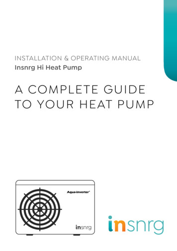
9. Exploded Diagram and Maintenance9. 1 Exploded DiagramModel 5 kw- 23 -
Part NameNO1Front grill2Front panel3Fan blade4Fan motor5ERP codePart NameNOERP code28Pipes temperature sensor collet11190000429Pipes temperature sensor11190000411360001730Back grill1114005331Ambient temperature sensor112200141Fan motor bracket111013003032Ambient temperature sensor clip1137150016maintain board111021003133Top cover7Base tray111016010234Compressor wiring clip1101000388Compressor11010003835Water flow switch1121000219Temperature sensor of water-in11220013336isolation panel111011002710Titanium heat exchanger11390007737controller box11Panel on the side111002102938Cable fixing clamp-up12Drainage hole plug11370007739Cable fixing clamp-down13Suction valve11250001940Terminal blocks14Cable joints11400018441controller box cover15Pressure guage11080000142PC board16Controller11220014943Capacitance clamp17Waterproof box11371200144Capacitance11130001418Panel on the side111002102945Transformator11220006419Water inlet/outlet bolt11400001546Fan motor capacitance11130000220Suction pipe111799166247Pillar111007004321Exhaust pipe111799166248Grill on the side111009001922Pipe (4 way valve to evaporator)1117991662494 way valve23Pipe (4 way valve to heat exchanger)111799166250Pipe (heat exchanger to capillary)111799164424Water inlet/outlet screw cap11390005251Liquid separator111799164425Capillary111799166252low pressure protection switch11210000326Collection pipes111799166253high pressure protection 1831110220010112600001Z1Z08Y31310. Maintenance(1) You should check the water supply system regularly to avoid the air entering the system and occurrenceof low water flow, because it would reduce the performance and reliability of HP unit.(2) Clean your pools and filtration system regularly to avoid the damage of the unit as a result of the dirty ofclogged filter.(3) You should discharge the water from bottom of water pump if HP unit will stop running for a long time(specially during the winter season).(4) In another way, you should check the unit is water fully before the unit start to run again.(5) After the unit is conditioned for the winter season, he is preconize to cover the heat pump with specialwinter heat pump.(6) When the unit is running, there is all the time a little water discharge under the unit.- 24 -
11. Warranty and returns11.1 WarrantyLIMITED WARRANTYThank you for purchasing a heat pump from us.This warranty covers manufacturing and material defects in all components for a period of two years after thedate of purchase.This warranty is limited to the original purchaser in the retail sector. It is not transferable, and it is not applicableto products that have been removed from their original installation location. The liability of the manufacturer islimited to the repair or replacement of defective components and does not include the cost of labour forremoving and replacing the defective component(s), the cost of transporting component(s) from or to the factory,or costs associated with other materials necessary for carrying out repairs. This warranty does not cover anydefects attributable to the following causes:1.Installation, operation or maintenance of the product other than in accordance with the guidelines and/orinstructions in the Installation and Operation Manual supplied with the product.2.Faulty or deficient work performed on the product by an installer.3.Failure to maintain the correct chemical balance in the swimming pool [pH between 7.0 and 7.8; totalalkalinity (TA) between 80 and 150 ppm; free chlorine concentration between 0.5 and 1.2 mg/l; totaldissolved solids (TDS) less than 1,200 ppm; maximum salt concentration 8 g/l].4.Improper use, modification, accident, fire, flood, lighting strike, rodents, insects, negligence, neglect, orforce majeure.5.Deposits, freezing, or other conditions that impair proper water flow through the product.6.Operating the product with a flow rate outside the published minimum and maximum specifications.7.Use of components or accessories not designed or made for this product.8.Chemical contamination of the air used by the product or improper use of decontaminating chemicals,such as the addition of decontaminating chemicals through the skimmer or in the pipes or lines located upstreamof the heat pump and the cleaning hose.9.Overheating, improper electrical connections, improper power supply, secondary damage attributable todefective O-rings, diatomaceous filters or filter cartridges, or damage caused by putting the pump into operationin the absence of sufficient water.LIMITATIONS ON LIABILITYThis is the sole warranty provided by the manufacturer. Nobody is authorised to grant other warranties in ourname.THIS WARRANTY REPLACES ALL OTHER EXPLICITLY GRANTED OR IMPLICITWARRANTIES, INCLUDING BUT NOT LIMITED TO ANY FORM OF IMPLICIT WARRANTY OFSUITABILITY FOR A PARTICULAR PURPOSE OR FITNESS FOR SALE. WE EXPLICITLYDISAVOW ANY LIABILITY FOR INDIRECT, INCIDENTAL OR CONSEQUENTIAL LOSS ORDAMAGE OF A PUNITIVE NATURE RESULTING FROM THE VIOLATION OF AN EXPLICITLYGRANTED OR IMPLICIT WARRANTY.This warranty gives you specific legal rights, which may vary depending on the country.WARRANTY CLAIMSTo ensure prompt handling of your warranty claim, please contact your dealer and provide the followinginformation to the dealer: proof of purchase, model number, serial number and date of installation. The installerwill contact the factory to obtain instructions regarding the procedure for making warranty claims and to find outthe location of the closest service centre.All returned components must be marked with a RMA number so that it can be determined whether they arecovered by the warranty.- 25 -
11.2 RMA request formCompany:Street Phone:Fax:E-mail:Contact:Date:Reserved for internal useRMA no.:Assigned by:Reason for return:Date:Copy of customer invoice included?RMA request accompanied by other documents?Description of the documents:Model no.:Serial number:Problem:Invoice no.:Invoice date:Warranty repair policy1.Shipping costs for returned products must be paid in advance. All shipping costs associated with a return shipment are borne byyou.2.Products may be sent back to us only after prior approval by the company. Return shipments for which approval has not been givenby the company will be sent back, with all shipping costs to be borne by you.3.We will replace or repair the products and return them to you free of charge using the shipping service of your choice.4.If you choose express shipment (by a shipping service selected by you), you are responsible for paying the shipping costs.Return procedure1.Before requesting an RMA number from us, please check whether you have properly observed the installation and use instructionsin the manual.2.Contact our RMA department by phone and ask for an RMA request form.3.Ensure that all fields of the RMA request form are fully completed.4.In the case of returns during the warranty period, please include the customer copy of your original sales invoice.5.Send the RMA request form, the sales invoice and any
allowable flow through the heat exchanger of the heat pump. 3. Install the heat pump above the water level of the swimming pool. 4. Always place the heat pump on a solid foundation and use the included rubber mounts to avoid vibration and noise. 5. Always hold the heat pump upright. If the unit has been held at an angle, wait at least 24 hours