Transcription
Design, Generation and Tooth ContactAnalysis (TCA) of Asymmetric FaceGear Drive With Modified GeometryFaydor L. Litvin and Alfonso FuentesUniversity of Illinois at Chicago, Chicago, IllinoisJ. Matthew HawkinsRolls-Royce, Allison Engine Company, Indianapolis, IndianaRobert F. HandschuhU.S. Army Research Laboratory, Glenn Research Center, Cleveland, OhioJanuary 2001
The NASA STI Program Office.in ProfileSince its founding, NASA has been dedicated tothe advancement of aeronautics and spacescience. The NASA Scientific and TechnicalInformation (STI) Program Office plays a key partin helping NASA maintain this important role. The NASA STI Program Office is operated byLangley Research Center, the Lead Center forNASA's scientific and technical information. TheNASA STIProgram Office provides access to theNASA STIDatabase, the largest collection ofaeronautical and space science STI in the world.The Program Office is also NASA's institutionalmechanism for disseminating the results of itsresearch and development activities. These resultsare published by NASA in the NASA STI ReportSeries, which includes the following report types: SPECIAL PUBLICATION. Scientific,technical, or historical information fromNASA programs, projects, and missions,often concerned with subjects havingsubstantial public interest. TECHNICAL TRANSLATION. Englishlanguage translations of foreign scientificand technical material pertinent to NASA'smission. TECHNICAL PUBLICATION. Reports ofcompleted research or a major significantphase of research that present the results ofNASA programs and include extensive dataor theoretical analysis. Includes compilationsof significant scientific and technical data andinformation deemed to be of continuingreference value. NASA's counterpart of peerreviewed formal professional papers buthas less stringent limitations on manuscriptlength and extent of graphic presentations.CONFERENCE PUBLICATION. Collectedpapers from scientific and technicalconferences, symposia, seminars, or othermeetings sponsored or cosponsored byNASA.Specialized services that complement the STIProgram Office's diverse offerings includecreating custom thesauri, building customizeddata bases, organizing and publishing researchresults., even providing videos.For more information about the NASA STIProgram Office, see the following:, Access the NASA STI Program Home Pageat http:llwww.sti.nasa.gov TECHNICAL MEMORANDUM. Scientificand technical findings that are preliminary orof specialized interest, e.g., quick releasereports, working papers, and bibliographiesthat contain minimal annotation. Does notcontain extensive analysis.E-mail your question via the Internet tohelp@sti.nasa.gov Fax your question to the NASA AccessHelp Desk at 301-621-0134 Telephone the NASA Access Help Desk at301--621-0390CONTRACTOR REPORT.Scientific andtechnical findings by NASA-sponsoredcontractors and grantees. Write to:NASA Access Help DeskNASA Center for AeroSpace Information7121 Standard DriveHanover, MD 21076,.
NASA/TMm2001-2106143 1176014539259r:.RESEARCHLABORATORYU.S. ARMYi.1Design, Generation and Tooth ContactAnalysis (TCA) of Asymmetric FaceGear Drive With Modified GeometryFaydor L. Litvin and Alfonso FuentesUniversity of Illinois at Chicago, Chicago, IllinoisJ. Matthew HawkinsRolls-Royce, Allison Engine Company, Indianapolis, IndianaRobert F. HandschuhU.S. Army Research Laboratory, Glenn Research Center, Cleveland, OhioNational Aeronautics andSpace AdministrationGlenn Research Center4January 2001ARL-TR-2373
AcknowledgmentsThe authors express their deep gratitude to the Army Research Office and members of UIC-IndustryConsortium for the financial support of the performed research.Gear Research aAvailable fromNASA Center for Aerospace Information7121 Standard DriveHanover, MD 21076Price Code: A03National Technical Information Service5285 Port Royal RoadSpringfield, VA 22100Price Code: A03Available electronically at http: / / gltrs.grc.nasa.gov/GLTRS
DESIGN GENERATION AND TOOTH CONTACT ANALYSIS (TCA) OFASYMMETRIC FACE GEAR DRIVE WITH MODIFIED GEOMETRYFaydor L. Litvin, Alfonso FuentesGear Research CenterDepartment of Mechanical EngineeringUniversity of Illinois at ChicagoChicago, Illinois J. Matthew HawkinsRolls-Royce, Allison Engine Co.Indianapolis, IndianaRobert F. HandschuhU.S. Army Research LaboratoryNational Aeronautics and Space AdministrationGlenn Research CenterCleveland, OhioSUMMARYA new type of face gear drive for application in transmissions, particularly in helicopters, has been developed.The new geometry differs from the existing geometry by application of asymmetric profiles and double-crownedpinion of the face gear mesh. The paper describes the computerized design, simulation of meshing and contact, andstress analysis by finite element method. Special purpose computer codes have been developed to conduct the analysis. The analysis of this new type of face gear is illustrated with a numerical example.NOMENCLATURE,ai (i r,q)parabola coefficient of driving (i r) and coast (i q) sides of parabolic rack-cutter profile (fig. 13)aptparabola coefficient applied for tool plunging (figs. 4 and 14)C1set of functions with continuous derivatives up to the first order at leastEcurrent value of shortest distance between the axes of the pinion and the grinding disk (fig. 4)E0nominal value of E (fig. 4)fequation of meshingL i (i 1,2)inner (i 1) and outer (i 2) limiting dimensions of the face gear (fig. 12)Ioparameter of translation measured along axis :k (fig"4)la,lcdistances Iaaot[ andMji,Ljimatrices 4 4 and 3x3 for transformation from S i to Sj of point coordinates and projectionsof vectorsNASA/TM--2001-210614[aco,[,respectively (figs. 5 and 7)1
N i (i s, 1,2)number of teeth of the shaper (i s), pinion (i 1), and face-gear (i 2)ni (i t. D)surface unit normals of the imaginary shaper rack-cutter surface (i t), shaper tooth surface (i s),parabolic rack-cutter surface (i r), pinion tooth surface (i 1), face-gear surface (i 2), andgrinding disk surface (i D)Pdiametral pitchp(0)candidate to contact pointpcircular pitchra, rp, rb(i)radii of addendum, pitch, and base circles for driving (i d) and coast (i c) sides (figs. 3 and 8)Scoordinate systems (k t, b)width of space of the tooth (k 0 and the blank (k b) of the generating imaginary rack-cutter(fig. 5)TTorque (fig. 27)ud, 0dShaper rack-cutter surface parametersur, OrPinion parabolic rack-cutter surface parameterswk(k t,b)Width of the space of the tooth (k t) and the blank (k b) of the being generated gearx/ ,Yk,zAxes of coordinate system Ski (i d,c)pressure angles for asymmetric face-gear drive for driving (i d) and coast (i c) sides (figs. 3,5,and 7)7shaft angle (fig. 16)tmcomplementary shaft angle (figs. 9, 10 and 12)AEchange of shortest distance between the pinion and the face-gear axes (fig. 16)Aqaxial displacement of face gear (fig. 17)Aychange of shaft angle (fig. 17)0Dsurface parameter of the grinding disk'tratio of tooth thicknesses of the imaginary asymmetric rack-cutterrangle applied for orientation of the pinion space in coordinate system S1sangle applied for orientation of the shaper space in coordinate system Ss (fig. 8)Y I(1)profile crowned pinion tooth surfaceY I(2)double-crowned pinion tooth surfaceNASA/TM--2001-210614,2
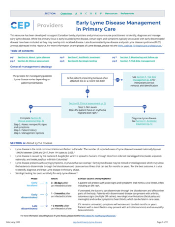
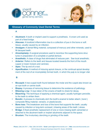
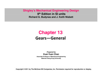
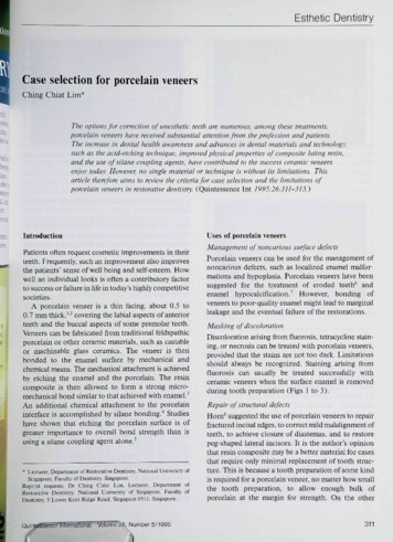
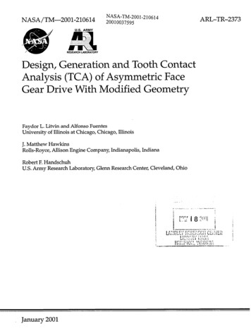
Xdgrinding disk surfaceErpinion parabolic rack-cutter surfaceEtshaper rack-cutter surfacei(i s, 2)angles of rotation of the shaper (i s) and the face gear (i 2) performed in the process ofgeneration of the face gear (fig. 10)Usangle of rotation of the face-gear shaper performed in the process of generation (fig. 5)1. INTRODUCTIONFace gear drives have found an important application in helicopter transmissions. Such gear drives, if speciallydesigned, enable to split the torque as shown in figure 1. The technology of face gear drives, in comparison withspiral bevel gears, is more simple. However, face gear drives require hardening of gear tooth surfaces (with following grinding) to obtain tooth strength that is equivalent to the same criteria of spiral bevel gears.The existing design of face gear drives is based on application of a conventional involute spur pinion being incontact with the conjugated face-gear (fig. 2). Errors of misalignment of such a gear drive may cause edge contactand even separation of tooth surfaces. Therefore, for the purpose of localization of bearing contact, the face gear isgenerated by an involute shaper with increased number Ns of teeth, where Ns - N 1 1 to 3 (N1is the pinion toothnumber).Investigation of face-gear drives was the subject of research accomplished by representatives of the Universityof Illinois at Chicago, Boeing, NASA Glenn Research Center and Lucas Western (refs. 8 to 10).The purpose of this paper is to develop a modified geometry of face-gear drives with reduced stresses andlow transmission errors. Two versions of modified geometry have been investigated and compared by analysis ofstresses and simulation of meshing and contact.Rotorshaftoutput-7/r- SungearNOTAR TMoutput.-nItCombining //%X",.Face-gears" //\Engineinput-Figure1. 2001-2106143
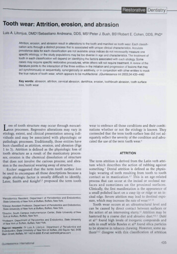
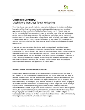
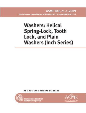
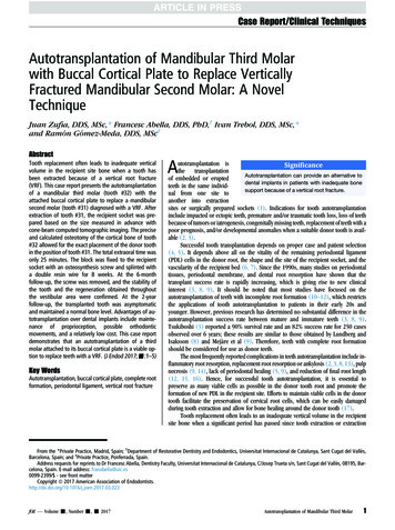
Figure2.--Face-geardrivewithspurpinion.The modification of geometry considered in the paper is based on the following principles:(l) The pinion is provided by tooth profiles that slightly deviate from conventional involute profiles, whereinthe shaper is provided by conventional involute profiles.(2) Profile deviation of the pinion we call profile crowning. It will be shown below (see section 5) that pinionprofile crowning provides a predesigned parabolic function of transmission errors. Such a function is able to absorbalmost linear discontinuous functions of transmission errors (caused by misalignment) (ref. 7) that are the source ofvibration and noise.(3) The pinion is designed with asymmetric profiles, larger pressure angle is provided for the driving side. Profiles of the shaper are asymmetric involute profiles (fig. 3).(4) The localization of the bearing contact of face gear drive is obtained by crowning of pinion tooth surfacein longitudinal direction. This can be achieved by plunging of the tool (disk or grinding worm) that generates thepinion (fig. 4).(5) We call the pinion double crowned, if it is crowned in profile and longitudinal directions. We remind thatthe purpose of profile crowning is predesign of a parabolic function of transmission errors, wherein longitudinalcrowning is required for localization of bearing contact.The contents of the paper cover: (1) Development of geometry of the pinion, shaper, and face-gear; (2) Simulation of meshing and contact of the pinion and gear; (3) Stress analysis of face gear drive.2. IMAGINARY RACK-CUTTERSThe concept of imaginary rack-cutters is applied for determination of geometry of spur pinion of the driveand the shaper that generates the face gear. We consider two approaches applied for profile crowning, describedas follows.Approach 1A common imaginary rack-cutter is applied for generation of asymmetric profiles of the pinion and the shaper(fig. 5(a)). The asymmetry of profiles means that pressure angle ctdfor the driving side is larger than the pressureangle c for the coast side. Parameters ud and uc determine the locations of current points M and N of profiles. Theprofiles of the rack-cutter are represented in coordinate system St (fig. 5(a)). During the process for generation, therack-cutter and the pinion (shaper) perform related motions (fig. 5(b)).NASA/TM--2001-2106144
XdQ XcS. aaOFigure3.wlllustrationof asymmetricinvoluteprofiles.Yk, Y2Y2,YkYdYa//,ItIEo- aplEZa 01Xkx1ZlFigure 4.reGeneration of pinion by plungingdisk.NASA/TM 2001-2106145,g
OtSb(a)StYtYs1 xt(b)Figure 5.mFor derivation of shaper and shaper rack-cutter tooth surfaces.Profile crowning of the pinion with respect to the shaper is achieved since the number Ns of teeth of the shaperis increased with respect to the number N 1of teeth of the pinion. The spur pinion and the face-gear generated bythe shaper are in point contact and therefore the bearing contact is localized. Longitudinal crowning of the pinion,obtained as shown in figure 4, is usually not provided. The pinion and shaper generated by the common rack-cutterare in internal tangency as shown in figure 6.There are two disadvantages of this approach:(1) High precision of manufacturing and assembly is required to avoid separation of tooth surfaces and edgecontact. The gear drive is especially sensitive to change A7 of shaft angle in the cases, wherein the axes are stillintersected or become crossed.NASA/TM--2001-2106146
Yl' Ya Pitchcircles .'"atxIFigure6.mTangencyof pinionandshapertoothprofiles.(2) The dimensions of instantaneous contact ellipse are controlled by difference (Ns -NI) only. Longitudinalpinion crowning accomplished as shown in figure 4 is not applied.The imaginary rack-cutter of asymmetric involute pinion or shaper is designed as nonstandard one (ref. 6), andits parameters st and sbare related by the coefficient;Lt st(1)Sb't is all assigned input parameter. Rolling of the pitch line with respect to the pitch circle of the being generated gear in the process of generation is provided. Therefore, we have thatwherest wb(2)Sb Wt(3)where wk(k t,b) is the width of space of the tooth and the blank of the being generated gear. It is easy to be verifiedthatSt Wt Sb Wb ----p where p and P are the circular and diametral pitches. Therefore,t PNASA/TM--2001-2106147t -P(4)
stprSb 1 ' t (1 Zt)------(6)Drawnings of figure 5 yield thatsb -cos O d-(7)cos cwhere 1d IQ'Q-- t[and 1c IQ--- tl.Radii of base circles of driving and coast side profiles are of different magnitude, since different pressure anglesfor both sides of profiles are assigned. Radii of base circles and operating pitch circles (centrodes) are related by theequationNrb(i) rp cos t i -cos t i(i d, c)(8)where rp is the radius of the respective centrode (of the pinion or the shaper), N is the respective number of teeth(of the pinion or the shaper), P is the diametral pitch, and cti is the pressure angle of the side considered.Henceforth we shall consider four base circles: two for the driving and coast sides of the pinion and two forthe respective sides of the shaper. There are two values ctd and c c of the pressure angles, for the driving side andcoast sides, and czd (respectively, ctc) is the same for the pinion and the shaper. The pair of base circles of the pinion(respectively, of the shaper) have a common center.Approach 2This approach is based on following considerations:(1) Two different imaginary rack-cutter are applied for generation of the shaper and the spur pinion (fig. 7).(2) The shaper rack-cutter is provided with asymmetric straight-line profiles and therefore it will generateasymmetric involute shaper profiles. The geometry of the straight-line profile rack-cutter has been discussed above.(3) The pinion rack-cutter is provided with parabolic profiles, asymmetric as well, that slightly deviate fromstraight-line profiles of the shaper (see section 5). This enables, as shown below, to obtain a predesigned parabolicfunction of transmission errors that can absorb linear functions of transmission errors caused by misalignment(ref. 7).(4) In addition to profile crowning, longitudinal crowning is provided by tool plunging in the process of generadon of the pinion (fig. 4).Shaperrack-cutter--\. ,--- Pinionrack-cutter--Driveside-- /,-- Coastside//Figure7. Shaper and pinionrack-cutters.NASA/TM--2001-2106148/
3. GEOMETRY OF FACE-GEAR TOOTH SURFACESThe face-gear tooth surfaces Y-'2are generated by asymmetric involute shaper. The shaper is generated by anasymmetric rack-cutter shown in figure 5. The derivation of face-gear tooth surfaces is based on consideration oftwo following enveloping processes applied in following sequence:(1) The shaper tooth surfaces Es are determined as envelopes to rack cutter surfaces shown in figure 5.(2) Then, the sought-for tooth surfaces of the face-gear are determined as envelopes to shaper tooth surfaces.Derivation of Shaper Tooth SurfaceFigure 5(a) shows the shaper rack-cutter profiles. Figure 5(b) is the schematic of generation of shaper toothsurface by the rack cutter.The derivations below correspond to generation of driving tooth surface. Plane Yt 0 and cylinder of radius rsare the axodes in the process for generation (fig. 5(b)). Parameters ud and 0d are the rack-cutter surface parameterswherein udis measured from point Qd, and 0d (not shown in fig. 5(a)) is measured from Qdin the direction that isparallel to axis :rRack-cutter surface Et is represented in coordinate system St by the following vector function rt(Ud,Od)ttd sintx d -l d cos t dq ]ud cOSa d ld sin a d]Ol 1,9,Here: d is the pressure angle of driving profile; Id dOt.The rack-cutter surface unit normal is represented in asnt [c0sad-sint d0 ]T(10)During the process of shaper generation, the rack-cutter and the shaper perform related translational and rotational motions as shown in figure 5(b). Axis I-I is the instantaneous axis of rotation.The shaper tooth surface Es is represented as followsrs (Ud,Od, s) Mst (IVs)rt(Ud,Od)fst (Ud' IPrs) Ud - I srssin a d 0(I I)(12)where,00 s)Mst [ -sin(Vsc S(Vss)0c S(Vssin(Vs0 s)s)1000 rs(COS(lgrs (sin(gtss s) lgssin(Vss)- 1Igsc S(Vs s))] s))](13)Angle s is a fixed angle introduced to relate orientation of coordinate system Ss with the shaper space as shownin figure 8.NASA/TM--2001-2106149
YsCoast sider tto shaperspace.Equation (11) represents in Ss the family of rack-cutter surfaces. Equation (12) is the equation of meshing ofshaper rack-cutter and shaper, that may be derived as represented in reference 7.Equations (11) and (12), considered simultaneously, represent shaper surface Es by three related parameters.Taking into account that equations (11) and (12) are linear with respect to parameters ud and 0d, it is easy eliminateone of them and represent surface Es in terms of two parameters.Derivations similar to discussed above enable to derive the coast side surface of shaper.Derivation of Face-Gear Tooth Surface E2: Surface Z2 is the envelope to the family of shaper tooth surfacesrepresented in coordinate system S2. Generation of Y2 by the shaper is represented schematically in figure 9. Theshaper and the face-gear perform rotations about axes zs and -'2related as 21 s NJN 2.We apply for derivation of E2coordinate systems shown in figure 10. Here: (1) movable coordinate systemsSs and S2 are rigidly connected to the shaper and face-gear, respectively; (2) fixed coordinate system Smis rigidlyconnected to the housing of the generating equipment, and Sp is an auxiliary fixed coordinate system.The shaper tooth surface Es, after transformations of equations (11) and (12), is represented in coordinate system Ss by the following vector equation-X s (Ud, lts (Ud ))"rs (ud,0d, Ilts(ud)) rs (ud, 0d) ys(Ud,q/s(Ud))od(14)1Here:xs (ud, qls (ud)) (ud sin a d - ld cos a d) cos(q/s s) (ud cos ad Id sin a d)sin( s s) rs(sin(q/s s) - q/s c s(q/s s)NASA/TM--2001-21061410(15)
Face-gearYmr-- Shaperw(S)Os,Omw(2)zs3'mz2Figure9,---Schematicof generationof face-gear.ys(Ud,Vs(Ud)) (UdCOStXd ld sin tXd)c s(Igs s) (ud sin a d -- ld cos ad)sin(V/s s) rs(c s(q/s s) q/s sin(q/s s))(16)Parameter s can be replaced by ual(rs sin COd).The unit normal to shaper tooth surface ns( s(Ud)) is represented asSurface 2 of the face-gear is determined as the envelope to family of shaper surfaces Es by the followingequationsr2(Ud,Od, s) M2s( s)rs(Ud,Od)"f2s (Ud,Od,( s) rs costXd(1--m2s cos 7m)- m2sOdsin /m COS(O d-I- s(18)"4- s -- s ) 0(19)Equation (18) represents in S2 the family of surfaces Es. Equation (19) is the equation of meshing. Matrix M2sdescribes the coordinate transformation from Ss to S2and is represented asNASA/TMm2001-21061411
YmYsXsxm(a)Os' Omxm, XpIz,0 2/" -I-Zp,Z2(b)Figure lO.---Coordinate systems applied for generation of face-gear tooth surface 2.(a) Illustrationof rotation of shaper. (b) Illustrationof rotation of face-gear.cosCscos 2- sin s cos#2sin 7msin 2 07, cosy msin ssin@ cosy mcOStssin@- cos s sin 2sin s sin 2M2s sin Ymcos 2 0 cosYmsin#s cos#2 cosy mcos#s cos 2-siny msin#s-siny mcOStscosy m00001(20)The unit normal to the face-gear surface Y-'2is represented in S2 asnE(Ud,Od,O s) L2s( )s,Od)ns(U d)(21),iThe 3 3 matrix L2s in equation (21) and in similar derivations is a submatrix of the 4x4 matrix M2s. It isobtained by elimination of the last row and column of M2s. Elements of matrix L2s represent the direction cosinesformed by respective axes of coordinate systems S2 and Ss (ref. 7).NASA/TM 2001-21061412
4. AVOIDANCE OF UNDERCUTTING AND POINTING The structure of the tooth of symmetric face-gear is shown in figure 11. The tooth surface is covered with contact lines L2s between the face-gear and shaper surfaces. The fillet surface is generated by the edge of the addendumof the shaper. Line L* is the line of tangency of the contact lines L2s with the fillet surface.Dimension of L I and L 2(fig. 12) determine the zones free of undercutting and pointing, respectively. Determination ofL 1and L2is represented in reference 7.For the case of an asymmetric face-gear, undercutting conditions have to be determined for both tooth sides, thedriving one and the coast side of the tooth. Undercutting will ocurr at the side with lower pressure angle. Therefore,undercutting conditions for the coast side of the tooth surface will limit the inner limiting parameter L 1 (fig. 12).Determination of pointing conditions of symmetric face-gear drive, as discussed in reference 7, can be used todetermine limiting outer dimension L2 of the face-gear (fig. 12). For asymmetric face-gear teeth, the location oftooth pointing area may be determined considering the intersection of the driving side and the coast side tooth surfaces at the top land of the tooth. A computer program to the solution of this problem has been developed. Increaseof the pressure angle of the driving side decreases the limiting outer dimension L2 of the face-gear.5. GEOMETRY OF DOUBLE-CROWNED PINION TOOTH SURFACESFormation of double-crowned pinion tooth surface is accomplished as follows:SteW p .--Weconsider as given surface Zr of a parabolic rack-cutter. Surface Zr generates pinion tooth surfaceEl(I) that is deviated in profile direction from a conventional involute tooth surface. This is achieved since pinionrack-cutter profile is a parabola but not a straight line (fig. 13(a)).Ste W p 2.---Consideringas known profile crowned pinion tooth surface El(1),we may determine the cross-sectionprofile of El(l) that coincides with the axial profile of disk surface Zo. Surface ED is a surface of revolution formedby rotation of disk axial profile about the disk axis.Ste W p 3.--Weconsider as known surface Eo of the grinding disk determined in Step 2. The double-crownedpinion tooth surface is generated as the envelope to family of disk surface Eo as follows:The motion of disk with respect to the pinion is performed as combination of: (1) translational motion along theaxis :k, rigidly connected to the pinion, and is parallel to axis :1 of the pinion coordinate system (fig. 14); (2) plunging translational motion accomplished in the direction ofy k axis, along the shortest distance E0 between the axes ofthe pinion and the disk (fig. 4). The plunging motion is executed in accordance to the equationE Eo - aptl2D(22)Contactlines L2sbetweenthefacegearand sharperFilletsurfaceFigure 11. Structure of the tooth of symmetric face-gear.NASA/TM 2001-21061413
Yn\\OragZnV ,1psOs, Om'YmL1L2x2Figure 12.mLimiting dimensions L1 and L2 of face-gear.YF Yl2Yrar'UrQrUr/(a)02I-aquq( r \r u0Qqr)- xr//rp(b)Figure13.mApplied coordinate systems for generation of the profile of the grinding disk.NASA/TM 2001-21061414"Xr
Yk,y 2)YD ID:apl12''1ok ,Zk ZD,Z 2)ODE011Figure14.--For generation of pinion double-crowned surface y 2).Here, 1o determines the translation along the pinion axis; apt is the parabola coefficient of the longitudinalplunging trajectory; E0 and E are the initial and current magnitudes of shortest distance between the axes of rotationof the pinion and grinding disk.The derivation below corresponds to the driving side of the pinion tooth surface. Similar derivations may beaccomplished for determination the coast side of the pinion tooth surface.Pinion Parabolic Rack-Cutter SurfaceFigure 13(a) shows the pinion parabolic rack-cutter profile. Figure 13(b) is the schematic generation of thepinion tooth surface Ell).Plane y r 0 and cylinder of radius rp are the axodes in the process of generation as shown in figure 13. Parameter ur and Or are the parabolic rack-cutter surface parameters, wherein ur is measured from point Qr along thetangent to the parabola at Qr' and Or (not shown in fig. 13(a)) is measured from Qr in the direction that is parallelto axis :r"Parabolic rack-cuttersurface X;r is represented in coordinate system Sr by the following vector function rr(ur,Or)"ur sinO drr (Ur,Or)j'-- Id COSOtd ar u2 COS dur cosotd ld sin cxd - arU2rsin a dOr1(23)where ar is the parabola coefficient of the parabolic rack-cutter profile.The parabolic rack-cutter unit normal nt(Ur)is represented in Sr ascos d - 2arUrsin d ]onr (ur) - sin o d - 2arUr cos ad JNASA/TM--2001-2106141541 4au1(24)
Pinion Profile Crowned Tooth SurfaceDuring the process of pinion generation, the parabolic rack-cutter and the being-generated pinion perform relatedtranslational and rotational motions as shown in figure 13(b).The profile crowned pinion tooth surface Ell) is represented as followsr(1) (tt r , Or, IFr) Mlr (IFr)r,. (ur, Or )2 3J r (ttr, lP'r) Ur - 2arUrld 2at Ur - rpqtr(2arUrCOSa d sin a d)(25) 0(26)whereMlr-cos(I/tr r)-sin( r r)00sin(I/tr r)c s(gtr r)000 rp(sin(q/r r)-q/rCOS(q/,. r))"0 I o(cos(I/tr r) r sin(q/r r))1001(27)Matrix M lr describes the coordinate transformation from Sr to S1.Application of angle r enables the orientationof axis Yl (fig"4) with the pinion space, as it was done for the shaper (fig. 8).Equation (25) represents in S1the family of rack-cutter surfaces Y r"Equation (26) is the equation of meshing ofZr and El(I).Equations (25) and (26), considered simultaneously, determine the profile crowned pinion tooth surfaceEl(I).The unit normal to the profile crowned pinion tooth surface nl(Ur, r) is determined asnl(Ur,lltr) Llr(gtr)nr(Ur)(28)Disk SurfaceThe procedure of derivation of grinding disk surface Zo is as follows:(1) Taking in equation (25) Or 0, we obtain the pinion tooth profile as the cross-section of Ztl) by plane z! 0.Equation (26) is linear with respect to Wrand the cross-section profile may be determined by vector function rl(Ur).(2) We apply for derivation of Y Dthe following coordinate systems: (a) S1that is rigidly connected to pinion (fig.15(a)), and (b) Sathat is a coordinate system related to the grinding disk, where we represent the disk axial profilelocated in plane (Ya'za)"The disk axial profile coincides with pinion cross-section profile and is determined in Sabyvector functionYl, YaYDYa, Xa, XDEoZD(a) L Z1(b)Figure15.mForgenerationof disksurface 'D"NASA/TM--2001-21061416
ra(Ur) Malrl(Ur)(29)where Mal [ ooo]1 00 100-E 00(30)1(3) The disk surface YD is generated by its axial profile wherein coordinate system Sa is rotated about axis x D(fig. 15(b)). Disk surface ED is represented in SD as followsr D(ur, 0D) MDa (0 D)Malr 1(u r)(31)whereM Da (OD) 0cos0D -sin 0osin 0 ocos 0ooo(32)Then, we obtainru(Ur,OD) yn(ur,OD)(33)'X D (Ur, 0 D )"L-o(Ur,Oo)whereXD(Ur,On) rpsin(I//r r ) -rpl r c s(I//'r r) In cos(ad Igr r ) Ursin(ad 1//r r ) (34)ar u2 c s(0 d I]/r r)YD (Ur,OD) COSOD(-E 0 rp cos(Ig r r ) rpVr sin(Vr - r) ID sin(ad I r r) //r cos(ad grr r) -aru2 sin(ad Igr r)):D(Ur, On) sin OD(--E0 rp COS(l//r(35) r) rp trsin(Igr r) IDsin(ad Vr r) Urcos(ad lptr arU2rsin(ad r r))r )-(36) The unit normal to the disk surface nD(u r, OD)is obtained as!n D (ur ,0D) LDa (0D)Laln 1(ur)NASA/TM--2001-21061417(37)
where nl(Ur) is the unit normal to the disk axial profile given byOr1-- k1/grnl(Ur) OrlOUr k 1I(38)and k I is the unit vector of the coordinate system S 1 in the direction of axis -1 given byk 1 [00Double-Crowned1]r(39)Pinion SurfaceWe remind that Zt2) is generated as the envelope to family of disk surfaces ZD wherein the disk performstranslational and plunging motions as shown in figure 4. We apply for derivation of El2) the following coordinatesystems (fig. 14): (1) SD that is rigidly connected to the generating disk; (2) an auxiliary fixed coordinate system Skwherein the motion of disk is represented; (3) coordinate system S 2)where the generated double-crowned piniontooth surface is represented. Then, we obtain(2)ri (Ur,OD,ID) (2)MlkflD(OD,ID) tanOD-IDMkD(ID)rD(Ur,OD)(40)2apl(41)Eo apll1 2]' 0whereMkd and100-ap1121l[!o0oo;Jo]r ,w(2)aVllk [ 00011001Eo0o 01(42)(43)Equation (40) represents the family of disk surfaces Zo. Equation (41) is the equation of meshing of generating2)disk and double crowned pinion tooth surface Zt .The normal to Zt2) is represented in coordinate syste m S t2)asn 2)(Ur, OD,ID) L(12)LkD([D)nD (Ur,OD)NASAfrM--2001-21061418(44)
6. COMPUTERIZED SIMULATION OF MESHING AND CONTACT The purpose of simulation of meshing and contact is investigation of influence of errors of alignment on transmission errors and shift of bearing contact. Simulation of meshing is based on an algorithm that provides continuoustangency of contacting surfaces (ref. 7). The tangency of surfaces is provided by observation of equality of positi
generation of the face gear (fig. 10) Us angle of rotation of the face-gearshaper performed in the process of generation (fig. 5) 1. INTRODUCTION Face gear drives have found an important application in helicopter transmissions. Such gear drives, if specially designed, enable to split the torque as shown in figure 1.