Transcription
NGP SERIES PISTONMETERING PUMPPARTS ANDINSTRUCTION MANUALNGP-6055 ShownJOHN BLUE COMPANYDIVISION OF ADVANCED SYSTEMS TECHNOLOGY, INC.165 Electronics Blvd, Huntsville, AL 35824Telephone: (256) 721-9090 - FAX: (256) 721-9091Toll Free: 1-800-253-2583www.johnblue.comPrinted in U.S.A.12-M-43Rev 12/19
SAFETY PRECAUTIONS Equipment should be operated only by responsible people.A careful operator is the best insurance against an accident.Fill system with WATER first and check output.Check all valves, fittings, hose clamps, etc. for wear / leaks before admitting process fluid to the system.Replace hoses when worn, cracked, or if leaking.WARNING: USE OF THIS PRODUCT FOR ANY PURPOSES OTHER THAN ITS ORIGINAL INTENT, ABUSEOF THE PRODUCT, AND/OR MODIFICATION TO THE ORIGINAL PRODUCT IS STRICTLY PROHIBITED BYCDS-JOHN BLUE COMPANY. JOHN BLUE COMPANY RESERVES THE RIGHT TO DENY WARRANTY ORLIABILITY CLAIMS IN ANY/ALL SITUATIONS INVOLVING MISUSE, ABUSE OR MODIFICATION.THE ORIGINAL INTENT OF THIS PRODUCT DOES NOT INCLUDE USE WHERE THE MAXIMUMALLOWED SPEED, PRESSURE, OR TEMPERATURE IS EXCEEDED, AND IT DOES NOT INCLUDEAPPLICATIONS UTILIZING FLUIDS THAT ARE NOT COMPATIBLE WITH THE PRODUCT’S COMPONENTMATERIALS. DO NOT USE THIS PRODUCT WITH FLAMMABLE OR COMBUSTIBLE FLUIDS SUCH ASGASOLINE, KEROSENE, DIESEL, ETC , AND DO NOT USE IN EXPLOSIVE ATMOSPHERES. FAILURE TOFOLLOW THIS NOTICE MAY RESULT IN SERIOUS INJURY AND/OR PROPERTY DAMAGE AND WILL VOIDTHE PRODUCT WARRANTY. IF IN DOUBT ABOUT YOUR APPLICATION, CONTACT YOUR STOCKINGDEALER OR THE JOHN BLUE TECHNICAL STAFF AT 1-800-253-2583.WARNING: This product can expose you to certain chemicals, which are known to the State of California tocause cancer or birth defects or other reproductive harm. For more information go to: www.P65Warnings.ca.gov.Important Message to Owners / Operators of PumpsEquipped with Lever Actuated Throw Out ClutchesWhen using a pump operated by a lever actuated throw out clutch, the rope must be routed by use of eyeletpulleys such that the rope cannot become entangled with or come in contact with any moving parts of the tractoror the applicator such as PTO shafts, tractor tires, ground drive units, etc. If eyelet pulleys are not found packedin with the pump, please contact your selling agent or John Blue Company (1-800-253-2583) immediately beforeany operations are undertaken.Verification must be made prior to any operation that the rope is clear of any moving parts while not only drivingstraight but when making turns either right or left. Verification must be made prior to any operation that theproperly routed rope contains no loops, which might become entangled with any part of the equipment oroperator.At no time should the rope be attached to any clothing worn by or to any body parts of the operator suchas hands, arms, legs, etc.We fully understand these are normal precautions owners / operators should take prior to and while operatingequipment. However, we wish to remind you that failure to comply with all safety regulations regarding instructingoperators in the use of moving equipment and actual operation of the equipment may lead to serious injury andpossible death.To The OwnerThis manual has been prepared and illustrated to assist you in the maintenance of your JOHN BLUE PUMP.Enter your serial number and the date of the purchase in the space provided below for future reference inservice information or for ordering parts. Because our engineering department is constantly improvingproducts, we reserve the right to make design and specification changes without notice.Model Number: Serial Number: Purchase Date: 2017 John Blue Co.2
TABLE OF CONTENTSSafety Precautions 2Note to the Owner . 2Table of Contents . . 3Pump Specifications . 3Introduction . 4Installation . 5Pump Setting . . .6Initial Start-Up of Pump . . .8Pump Calibration . .8Pump Accuracy . 8Maintenance . . . 9Storage . . 9Service Maintenance . . 10Crankcase Disassembly . . 12Parts List NGP-6050 & NGP-7050 [Single Piston] . . 14Parts List NGP-8050 & NGP-9050 [Double Piston] . . 16Parts List for Double Adjustable Double Piston . . . 18Parts List Optional Clutch . . 19Dimensional Footprints . 22Trouble Shooting . . 23Warranty . . 24PUMP SPECIFICATIONSUniversal SpecificationsOperating Pressure:MAX 120 PSIOperating Speed:MAX 450 RPMRotation:Clockwise or Counter-clockwiseDrive:No. 50 Roller ChainCrankcase Lubrication:SAE 90 Gear OilGrease Zerks:Multipurpose GreaseHLWModel SpecificationsPump Series:NGP-4055 NGP-5055 NGP-6050 NGP-7050 NGP-8050 NGP-9050Output Volume10.220.421.034.242.068.4Max Gal/MinOutput Disp.023.046.047.076.093.152Max Gal/RevRequired H.P.1.102.202.253.004.506.00TheoreticalPhysical 12565105125155Lbs.Crankcase Oil Cap.0.52.50.51.52.55.4PintsInlet/Outlet 0220220220220Optional Flanges 2017 John Blue Co.314x19x13 W x L x H (in.)Female Pipe ThdFlange Size
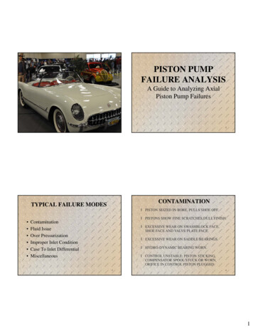
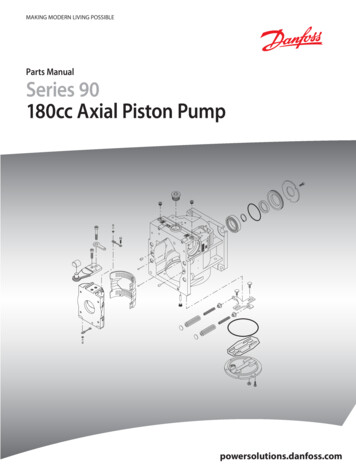
INTRODUCTIONThe NGP series pump is a positive displacement variable stroke metering pump. It is specifically designed toaccurately meter liquid fertilizer solutions. The pump’s construction is of rigid thick walled cast iron cylindersand manifolds for durability and long life. The check valves, piston, and rod are constructed of stainless steel forimproved corrosion resistance. Optionally, the pump may be purchased with stainless cylinders and manifolds.The NGP series pump functions as a positive displacement metering device which operates in direct relation tothe ground speed through a ground drive system (model number DRV-3xxx). The application rate can be set(covered under the “Pump Setting” section) before application begins and the GPA (gallons per acre) applicationwill be accurate regardless of the varying speeds of the drive mechanism.The NGP series pump may also be used with one of our hydraulic drive kits (model number VRH-xxx-xx) toprovide variable rate application when used with one of many different control systems. The pump providesseveral advantages over other types of pumps such as: suction capability from saddle tanks, stable settings thatdo not vary with temperature, and proven durability and longevity.The NGP series pump is designed to control the overall gallons of solution metered over an acre, independentof downstream discharge pressure (120 psi max). The only function of the flow divider or row orifices in a JohnBlue pump system is to divide liquid accurately row to row - not to meter the overall application rate.SprocketDischarge PortOil Fill PlugVent PlugOil Level PlugOptional FlangesShownRear - Not ShownOil Drain PlugRear - Not ShownRod PackingPistonPump SettingHub & PointerDischarge ValvesTop Position(Stiff Spring,Flat Side In)Not VisiblePacking Grease ZerkPistonPackingSuction ValvesBottom Position(Weak Spring,Flat Side Out) 2017 John Blue Co.Valve AccessCoverSuction Port4
INSTALLATIONMOUNTING The NGP pump should be mounted on a rigid base in a horizontal position. The mount position should allow for a straight drive chain and proper tightness. Chain idlers should be installed on the slack side of the drive chain. The supplied rubber washers are installed between the pump and mount. Caution should be exercised on implements with wings or folding members toassure that sufficient area is allowed around the pump and plumbing to notcause contact or binding. Verify that the rear tractor wheel will clear the pump during sharp turns. The oil vent plug should be installed in the oil fill located on top of crankcase.SUCTION PLUMBING An adequately sized 30 mesh strainer should be installed on the suction side of the pump and should bechecked at each tank filling for debris, which could cause suction restriction, starving the pump of flow. The NGP pump does produce suction to pull fluid from the tank; however, it is recommended to mount thepump level or below the tank, if possible, to assure the most effective and quickest prime. Install the process fluid suction line as straight as possible avoiding restrictions from kinks or extremelysharp turns. This will ensure even flow during maximum pump output. Quick connect fittings should be checked and double checked to verify that no leakage is present. Quickconnects, although commonly necessary, quite often can produce a suction leak if installed in a bindallowing air to enter the pump, causing loss of prime and / or reduction in pump output. It is recommended that suction line hoses be double clamped. Again, this is an area that can produce asuction air leak into the pump, even if no drip from the hose is present.DISCHARGE PLUMBING It is not recommended to install a discharge strainer as these could clog with debris causing significantdischarge pressure and possible system damage in positive displacement pump applications. Flow dividers may be installed either directly on top of the discharge port or remote mounted. Orifice applications must pay particular attention for proper orifice sizing for the specifiedapplication rate. WARNING: The flow range of an NGP pump far exceeds the flow curve of asingle orifice operating below 120 psi. For Example: An orifice application at 30 psi dischargepressure for a rate of 20 GPA @ 4 mph will produce 422 psi when the rate is adjusted to50 GPA and ground speed increased to 6 mph. It is recommend that for applications using a double piston pump with two flow dividers, removethe common manifold and plumb each flow divider independently to maximize accuracy. For variable rate and/or low rpm applications, a pulsation dampener for the pumpoutput line may be constructed utilizing a tee in the pump outlet port/line and avertical piece of pipe (16” long x 2” nom. pipe diameter).A dampener kit is available from CDS-John Blue for 1-1/2” ports: 116344-91(Note that for 1” NPT port pumps a reducing nipple will have to be used.) 2017 John Blue Co.5
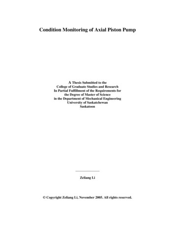
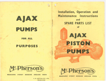
PUMP SETTINGThe NGP pump output is determined by the drive sprocket ratio and the stroke setting. There are two ways tofind the proper setting for your pump:1. Using the online flow rate calculator at www.cds-johnblue.com .The icon is on theright-hand side of the page, and there is a mobile version available here:2. Using the slide chart (115698-91) supplied with the pump – follow the example below:SPROCKETRATIOLOADED RADIUSSTANDARD SPROCKETCOMBINATIONSMAXIMUMGROUNDSPEEDGALLONS PER ACREPUMP SETTINGSWATH WIDTHSPROCKET RATIOStandard Sprocket CombinationsStandard sprocket combinations may be used for equipment with only one chain from the ground or press wheelsprocket to the pump sprocket. For example: an applicator with a 60 tooth drive sprocket on the tire driving a16 tooth driven sprocket on the pump can use the 16 to 60 mark on the slide chart.Non-Standard Sprocket CombinationsIf you are using sprocket combinations with multiple sprockets, such as with a jack shaft, use the followingformula to determine sprocket ratio:Drive Sprocket Sprocket RatioDriven SprocketFor example: an applicator with a 50 tooth on the drive wheel, driving to a 24 tooth on the jack shaft, then a 36tooth on the jack shaft driving up to a 16 tooth pump driven sprocket, would yield a 4.69 drive ratio.50 T (@ Drive Wheel)24 T (@ Driven Shaft)X36 T (@ Drive Shaft)16 T (@ Driven Pump) 5036X2416 4.69 Sprocket RatioSet the sprocket ratio on the slide chart using the 4.69 calculation for the example above. 2017 John Blue Co.6
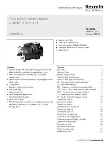
LOADED RADIUSThe measurement for the loaded radius must be from the Manufacturer of the tire or be measured under loadedconditions. The loaded radius tire is always the tire that has the first drive sprocket attached to its hub.Ground Wheel Drive ArrangementMeasure the loaded radius from the center of the hub to the bottom of thetire where it rests on the ground.Press Wheel Drive ArrangementMeasure the loaded radius from the center of the press wheel shaft towhere the wheel rests against the tire. The press wheel must be engagedfor normal operation to give an accurate reading.SWATH WIDTHTo determine the swath width, count the number of outlets and multiply bythe distance (inches) between any two outlets, nozzles, or shanks. Thisassumes that all outlets are equally spaced, if outlets are not evenlyspaced, figure the entire length of the boom or toolbar from end nozzleto end nozzle and allow for coverage beyond the ends.For example, an 11 row boom at 30” would have a swath width of 330”SETTING THE PUMPRead the desired pump setting from the bottom scale on the pump setting chart. Loosen the setting pointer nutand rotate the setting hub until the setting pointer is over the desired setting. The setting wrench will facilitaterotation of the setting hub. Once proper pump setting is achieved, tighten the setting pointer nut.EXAMPLE:An applicator is equipped with a NGP-6050 series pump, 11L x 15” tires, a 60 tooth drive sprocket, and a 16tooth pump driven sprocket. It is desired to apply 33 gallons per acre on a 360” swath. The following steps willdetermine correct pump setting:1. Set loaded radius of tire (13.5”) under the sprocket2SET SWATH WIDTHAT DIAMONDcombination of 16 to 60 in the top window.2. Set the swath width (360”) under the diamond in the middlewindow.3. Read that the pump setting is approx. 9 at 33 gallons peracre on the NGP-6055 scale in the bottom window.4. Set the pump to setting 9 to achieve 33 gallons per acreNote:The max. ground speed is read above the diamond asapprox. 9 mph to avoid exceeding 450 pump rpm.3 2017 John Blue Co.7READ PUMPSETTING1SET LOADED RADIUSAT SPROCKET RATIO
INITIAL PUMP START UPVerify that all installation guidelines have been followed as outlined in the installation section of this manual. Fill the tank full of water to test for leaks in the plumbing system and output of the pump. Fully open the valve at the tank allowing water to fill the suction line and check for leaks. Set the pump to pump setting 10. Before installing nozzles or orifices (if used), prime the pump and purge the system of air and foreignmaterial by slowly pulling the applicator 100 to 200 yards. Turn off the valve at the tank, open strainer, check for foreign material and clean the screens. The John Blue flow divider is automatic and requires no calibration; however, if nozzles or orifices areused, verify that the orifices are sized properly as to not produce high discharge pressure. Pull the machine over known acreage and verify the application accuracy with water prior to fieldapplication of chemical. Note that tank level marks can give false readings if read on uneven ground.PUMP CALIBRATIONThe NGP pump is calibrated from the factory; however, if the setting scale, hub, or pointer is replaced, use thefollowing procedure to calibrate the pump output with scale readings. Remove the valve cover and outboard cylinder (see maintenance section). Set the pump on pump setting 5 for all pump sizes. Rotate the crankshaft until the piston is as far in as it will go. Measure the distance from the end of thepiston to the inboard cylinder flange. Rotate the crankshaft until the piston is as far out as it will go andmeasure again to the same place. The difference in length is the stroke length, which at pump setting5 should be 9/16” for the NGP-4050, 5050, 6050, & 8050, or 15/16” for the NGP-7050 & 9050. If the distance is less than the required amount, reset the pointer at a higher setting, if it is greater; resetthe pointer at a lower setting. Repeat this procedure to obtain the required measurement. Once accomplished, loosen the setting scale screws until the 5 is directly under the pointer and secure thescale in position with the three scale screws. Replace the outboard cylinder and valve cover, making sure that the valves are in their proper orientationas covered under the maintenance section.PUMP ACCURACYA catch test may be performed to verify accuracy (not as a calibration method) by priming the pump andcatching all of the pumped fluid from the discharge for a known number of revolutions. See chart below:Pump SeriesPump Setting# of RevolutionsTotal Pump OutputNGP-40508-1/4101-1/2 PintsNGP-50508-1/4103 PintsNGP-60508103 PintsNGP-70508-1/4105 PintsNGP-80508106 PintsNGP-90508-1/41010 Pints 2017 John Blue Co.8
MAINTENANCE Check oil daily and fill crankcase to proper level with a quality grade SAE 90 weight gear oil. With the pumpsitting level, the oil should be within 1/2” of the bottom of the hole on back of crankcase. You may use along wire or zip tie as a dipstick to check the level – some length is required due to the hole’s depth. Lubricate all grease zerks on roller chain sprocket spacer, outboard cover plate, crankshaft end, and atstuffing box flange daily. Fill zerks until grease is visibly seen seeping from mating parts. For the stuffingbox flange zerk, grease will be seen seeping from the vent on the opposite side of the flange. Pump oil should be changed seasonally or more often in extreme use conditions. Visually inspect sprocket and drive chain daily for excessive wear or corrosion. Lubricate chain regularly toreduce corrosion. Chain alignment must be straight.STORAGEIMPORTANT – KEEP AIR OUT AND KEEP FROM FREEZINGKeep air out of the pump! This is the only way to prevent corrosion. Even for short periods of storage, theentrance of air into the pump causes RAPID and SEVERE CORROSION. Freezing temperatures can cause thefluid or water to freeze internally to the pump, which can cause severe damage to the wet-end castings.OVERNIGHTSuspension fertilizer must be flushed from the pump for ANY storage period. For Clear Liquids:1. Steady or rising temperatures: leave pump and hoses filled with solution. DO NOT DRAIN nor admit airto the pumps.2. Cooling weather: (solution likely to salt out), fill pump with water and leave filled. DO NOT admit air.3. Freezing temperature: fill pump with RV-antifreeze and leave filled, DO NOT admit air.ONE TO TWO WEEKSACCEPTABLE: Flush pump thoroughly with 5 to 10 gallons of a solution that will neutralize the liquid lastpumped (refer to that manufacturer’s instructions). Fill with clean water and DO NOT DRAIN.Keep pump sealed to exclude air. If freezing temperatures are remotely possible, the winterstorage procedure (see below) must be used to avoid damage to the pump castings.PREFERRED: Flush pump as detailed above. IMMEDIATELY fill all passages in pump with straight RVantifreeze which contains a rust inhibitor. Place 1-1/2” NPT PVC plugs in the suction anddischarge fittings to keep pump full and exclude air.WINTER STORAGE1. Flush pump as detailed above.2. With pump set on 10, draw in straight RV-antifreeze until the discharge is clean. If systemutilizes a flow divider (FD), pump the RV-antifreeze through the FD manifold until it is seen in thedischarge lines. Fill pump and plug suction and discharge fittings of pump to retain RV-antifreeze. 2017 John Blue Co.9
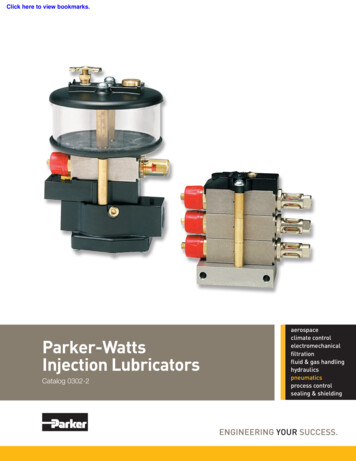
SERVICE MAINTENANCEProper maintenance of the NGP pump will ensure a service life for many years. Rebuilding and / or servicingcheck valves, piston flange packing, piston rod packing, and crankcase components is an economical way toensure optimum service. This type of service is simple, and can be done by almost all end users. The parts listand schematic section shows the position of all service kit items, which includes all seals, packing, andgaskets. Gasket kits and component parts can be ordered through any authorized John Blue distributor.CLEAN AND INSPECT CHECK VALVES Remove the valve cap exposing all 4 check valves. Take care inremoval to notice the orientation of the valves. Discharge valvesuse a tighter spring and are on top, flat side in. Suction valves usea weaker spring and in the bottom, flat side out. Valves should be removed by hand, do not use a screw driver orpry-bar as damage can result. Push each valve disc off its o-ringseat ensuring that the spring reseats each disc evenly and that nodebris is present. Inspect the o-rings for cuts or cracks whichcould allow air to enter or cause the discs to not seat properly. Check the port o-rings positioned near the top and bottom of theinboard cylinder in an oval shaped groove. This o-ring should notSuction ValvesDischarge Valvebe removed unless visible damage is present. The o-rings shouldbe fully installed in the groove with no cuts or cracks. Once all valves are checked for debris or damage ando-rings are in position, re-install valves in proper orientation, replace the cover, and tighten the bolts evenly.PISTON PACKINGS With valve cover removed, remove the ½” long bolts securing theoutboard cylinder. Remove the outboard cylinder exposing thepiston – gaskets, washer, and packing. Remove the first piston – packing, gasket, and washer; notice theorientation of the packing lip. Remove the second piston gasketand packing from the inboard cylinder; again noticing theorientation of the packing lip. Inspect the packing and replace if necessary, gaskets shouldalways be replaced once removed. The piston - packing shouldbe pliable and without cracks or nicks to perform properly. Clean the cavities of both the inboard and outboard cylinder aswell as the valve cap while disassembled. Discoloration of theplunger and / or lateral scoring of the piston can be deceiving, butnot necessarily detrimental.Piston – packingPiston – gasketPiston – washerPiston – gasketPiston - packing Inspect piston for deep grooves, radial scoring, or severe abrasion. The best method is by feel. Assemble in reverse manner taking care for proper orientation of the piston – packing, gaskets, and washer. 2017 John Blue Co.10
PISTON ROD PACKINGSThe rod packing consists of 2 sets of self-tightening ‘V’ rings which seal around the piston rod to preventpumped fluid from leaking and protect the crankcase from contamination. Virtually any leakage of the pumpedfluid through the vent in the side of the stuffing box is an indication that these rod packing need replacement.However, it is not uncommon for oil to drip form this drain.Removal of rod packing: With the valve cap and cylinders removed, remove the piston nutand piston by rotating piston counter-clockwise, use a belt wrenchPiston Rod Packingor cloth nearest to the nut end to prevent damage to the piston. Remove the stuffing box and gasket which house the wet-endpiston rod packing. Remove the snap ring from the end of the stuffing box, allowingthe washer, spring, and washer to slip out. The L-1031-2 insertshould not be removed from the stuffing box. The rod packing setcan be removed with a hook or screwdriver by prying the multipiece rod packing set out of the cavity. Once removed it must bereplaced with a new service rod packing set. There is no snap ring on the second set closest to the crankcaselocated in the crosshead guide. This set may be removed in thesame manner as the first set. There is a secondary o-ring rod seallocated at the bottom of the set which also should be replaced. Inspect the piston rod for any deep scoring and replace if necessary. A polished wear pattern may beevident and is not detrimental; however, deep grooves indicate the piston rod assembly should be replaced. The crosshead guide may be removed from crankcase to allow for inspection of the connecting rod bushing.If damaged or slop is present, this should be replaced.Re-assembly and replacement of rod packing: Carefully re-install the crosshead guide and gasket and bolt tocrankcase, if removed. Lubricate piston rod and install o-ring first, then carefully install thefirst ‘V’ ring packing set. The set consists of a bottom adapter, 4rings, and a top adapter. Each component should be inserted oneat a time and pressed firmly in place. The 4 rings have a ‘V’ shapeand are oriented so as the ‘V’ point is pointed towards thecrankcase, for both sets. Install the washer and spring. Install second set in the stuffing box in a similar manner, there isno secondary o-ring required in this set. Install the washer, spring,then washer and hold in place with snap ring. Lubricate piston rod and stuffing box, then slide stuffing box carefully back over rod, being extremely carefulto push straight on the piston rod so as the rods threads do not damage the ‘V’ ring set. Re-assemble piston, inboard, and outboard cylinder in reverse manner. Continue with valves in properorientation, valve cover, and secure all bolts evenly. Finally, lubricate the stuffing box grease zerk until grease seeps out of the stuffing box vent hole. 2017 John Blue Co.11
CRANKCASE DISASSEMBLYMajor pump repair requires some in-depth knowledge on working tolerances for internal parts. Werecommend that you contact your nearest John Blue sales and service dealer for best results in major pumprepair. Shaft oil seals have been upgraded from previous L & LM series pumps to include a wiper ring. The oilseals are enclosed in a greaseable cavity to flush debris from around the seal, which is a contributing factor topre-mature oil seal failure. The oil seals may be replaced by following the OUTBOARD & INBOARDCOMPONENTS section below. All instruction and visual representation in this section is shown with wet-endcomponents removed which is covered in the maintenance sections preceding this section.OUTBOARD COMPONENTS Remove the retaining ring, pump setting hub, and pointer. Remove the flange cover exposing the oil seal in its cavity. Remove the oil seal which may be done with a screwdriver, taking care not to scar the internal shaft or housing. Inspection of the stroke setting sleeve should be made forwear at the seal location as well as the flange gasket fortears prior to re-assembly.INBOARD COMPONENTS Remove the sprocket from shaft and sprocket spacer,inspecting the o-ring and thrust washer for wear, cuts, ordamage and replace as necessary. Remove the cover plate. It may be necessary to removeany marks in the crankshaft from the sprocket / spacerset-screws with a light emery cloth in order for the coverplate to slip off with the bearing. Remove the oil seal with a screw driver, taking care not toscar the housing or shaft. If only the oil seal is being replaced, the cover plate should be re-installed first, then the oil seal. Inspectthe shaft for wear at the seal location, as well as the cover plate gasket for tears, replace as necessary.INTERNAL COMPONENTSThe following inspection points should be made prior to disassembly if required: With inboard and outboard components removed, examine for sediment in the crankcase. A smallamount of metal wear and ‘grit’ in the oil is normal, large sediment may require further disassembly. Check for metal and/or fertilizer discoloration to the oil. If fertilizer is present, the crankcase should bedisassembled and each component examined for rust pitting or deterioration. Holding the crankcase firmly, take hold of the connecting rod and push / pull. If you feel obvious endplay, disassemble all components and inspect for wear, particularly the eccentrics and connecting rod. 2017 John Blue Co.12
INTERNAL DISASSEMBLYReference to the schematic section is recommended prior to disassembly of the internal crankcase componentsto familiarize yourself with components. The wet-end components, inboard, and outboard components shouldbe removed prior to internal disassembly as outlined in previous sections of this manual. Supporting the piston rod with a wood block, locate thecrosshead pin, which connects the piston rod and connectingrod and carefully drive pin out with a hammer and punch. Inspect the connecting rod bushing for damage and replace asnecessary during re-assembly. Slide the outer eccentric and eccentric pin out of the crankcase. The connecting rod can then be removed by carefully sliding itout the side of the pump at an angle. The shaft can then be removed as shown with the innereccentric still in place.Note:Double piston pumps will require the stroke transfersleeve to be removed with the shaft exposing thesecond piston eccentric and connecting rod for removal. The stroke setting sleeve is then removed. The eccentric pins may slide out during anypart of this process and should beaccounted for, single pumps utilize 1,double pumps utilize 3 [ref schematic]. Examine all components, giving moreattention to ones showing “galling” than toones which are undersize, yet smooth.CRANKCASE RE-ASSEMBLY All components in the gasket kit should be used during re-assembly. Reassemble the crankcase in reverse order. When assembling the shaft, oil the shaft o-ring and carefully insert into stroke setting sleeve. It is extremely important that all eccentric pins engage appropriate mating slots. Coat all bolts threads with gasket sealant before installing in crankcase. 2017 John Blue Co.13
PARTS LISTING – NGP- 405x / 605x / 705x SeriesNGP-4050NGP-6050NGP-7050PART DESCRIPTIONKEYSPROCKET RC50-18TPART #L-1020112661-01PART #L-1020112661-01PART #L-1020112661-0155-KNO SPROCKETNOT USEDNOT USEDNOT USED56-RSPROCKET RC40-18T113905-01113905-01113905-0135/16x3/8 SETSCREW9053290532905324GREASE FITTINGH-28H-28H-2855/16x3/8 SETSCREW9053290532905326SPROCKET S-3168THRUST WASHER115626-01115626-01115626-0195/16x1 HEX BOLT90637906379063710OIL SEAL115621-01115621-01115621-0111COVER PLATE115723-
formula to determine sprocket ratio: For example: an applicator with a 50 tooth on the drive wheel, driving to a 24 tooth on the jack shaft, then a 36 tooth on the jack shaft driving up to a 16 tooth pump driven sprocket, would yield a 4.69 drive ratio. Set the sprocket ratio on the slide chart using the 4.69 calculation for the example above.