Transcription
Shigley’s Mechanical Engineering Design9th Edition in SI unitsRichard G. Budynas and J. Keith NisbettChapterp13Gears—GeneralPrepared byKuei-Yuan ChanAssociate Professor of Mechanical EngineeringNational Cheng Kung UniversityCopyright 2011 by The McGraw-Hill Companies, Inc. Permission required for reproduction or display.
13 Gears—GeneralChapterOutline13-1Types of Gears13-2Nomenclature13-3Conjugate Action13-4pInvolute Properties13-5Fundamentals13-6Contact Ratio13-7Interference13-8The Forming of Gear Teeth13-9Straight Bevel Gears13-10Parallel Helical Gears13-11Worm Gears13-12Tooth Systems13-13Gear Trains13-14Force Analysis—Spur Gearing13-15Force Analysis—Bevel Gearing13-16Force Analysis—Helical Gearing13-17Force Analysis—Worm Gearing
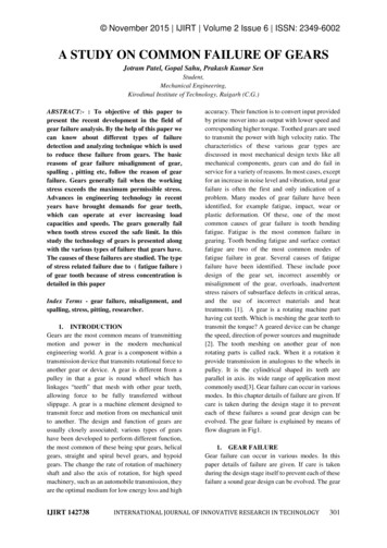
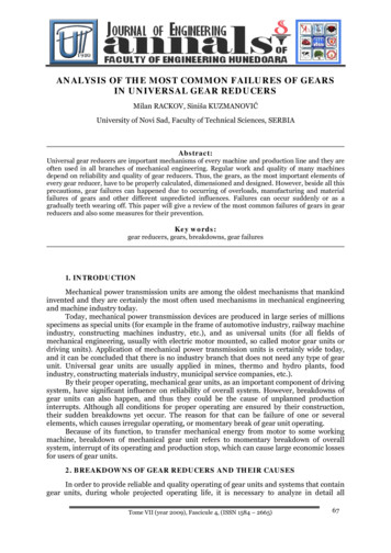
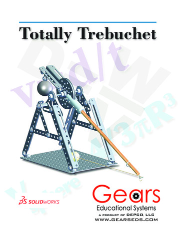
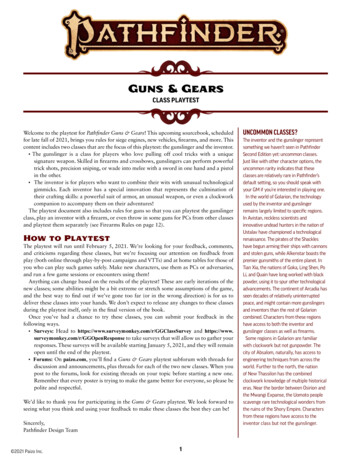
Types of Gears Spur gears have teeth parallel to the axis of rotation and are used totransmit motion from one shaft to another, parallel, shaft. Helical gears have teeth inclined to the axis of rotation. Helical gearsare not as noisy, because of the more gradual engagement of theteeth during meshing. Bevel gears have teeth formed on conical surfaces and are usedmostly for transmitting motion between intersecting shafts. Worms and worm gears ,The worm resembles a screw. Thedirection of rotation of the worm gear, also called the worm wheel,depends upon the direction of rotation of the worm and uponwhether the worm teeth are cut right-hand or left-hand.3
SPUR GEAR Teeth is pparallel to axis of rotation Transmit power from one shaft toanother parallel shaft UUsedd iin ElectricEl t i screwdriver,dioscillating sprinkler, windup alarmclock, washing machine and clothesydryer
External and Internal spur Gear Advantages:– Economical– Simple design– Ease of maintenance Disadvantages:– Less load capacityp y– Higher noise levels
Helical Gear The teeth on helical gears are cut at an angle to the face of the gear This gradual engagement makes helical gears operate much moresmoothly and quietly than spur gears Carry more load than equivalent-sized spur gears6
Helical Gear
Herringbone gears To avoid axial thrust,, twohelical gears of oppositehand can be mounted sideb side,byside to cancel resultingres ltingthrust forces Herringbone gears aremostly used on heavymachinery.
Rack and pinion Rack and pinion gears are used toconvert rotation (From the pinion) intolinear motion (of the rack) A perfect example of this is the steeringsystem on many cars
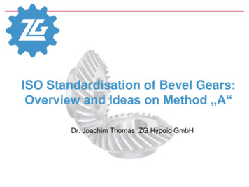
Bevel gears Bevel gears are useful when the direction of a shaft'srotationi needsd to beb changedhd They are usually mounted on shafts that are 90degrees apart,apart butb t can be designed to workork at otherangles as well The teeth on bevel gears can be straight,straight spiral orhypoid locomotiveslocomotives, marine applications,applications automobiles,automobilesprinting presses, cooling towers, power plants, steelplants, railway track inspection machines, etc.10
Straight and Spiral Bevel Gears
WORM AND WORM GEAR Worm ggears are used when largeg ggear reductions areneeded. It is common for worm gears to havereductions of 20:1, and even up to 300:1 or greater Many worm gears have an interesting property thatno other gear set has: the worm can easily turn thegear but the gear cannot turn the wormgear, Worm gears are used widely in material handlingand transportation machinery,machinery machine tools,toolsautomobiles etc12
WORM AND WORM GEAR13
Nomenclature9The pitch circle is a theoretical circle upon which all calculations are usuallybased; its diameter is the pitch diameter.9Appinion is the smaller of two matinggggears. The largerg is often called thegear.9The circular pitch p is the distance, measured on the pitch circle, from apoint on one tooth to a corresponding point on an adjacent tooth. It isequalto the sum of the tooth thickness and width of space.9The module m is the ratio of the pitch diameter to the number of teeth.9The diametral pitch P is the ratio of the number of teeth on the gear to thepitch diameter.14
Nomenclature9The addendum a is the radial distance between the top land and the pitchcircle (1m).9The dedendum b is the radial distance from the bottom land to the pitchpcircle (1.25m). The whole depth ht is the sum of the addendum and thededendum.9The clearance circle is a circle that is tangent to the addendum circle of themating gear.9The clearance c is the amount by which the dedendum in a given gearexceeds the addendum of its mating gear.9The backlash is the amount by which the width of a tooth space exceeds thethickness of the engaging tooth measured on the pitch circlescircles.15
Conjugate Action Tooth profiles are designed so as to produce aconstant angular velocity ratio during meshing,j gaction.conjugate When one curved surface pushes againstanother ,the point of contact occurs where the twosurfaces are tangent to each other (point c), andthe forces at any instant are directed along thecommon normal ab (line of action) to the twocurves.angular velocity ratio between the two arms is The angular-velocityinversely proportional to their radii to the point P. Circles drawn through point P are called pitchcircles, and point P is called the pitch point. To transmit motion at a constant angular-velocityratio, the pitch point must remain fixed; that is, allthe lines of action for every instantaneous point ofcontact must pass through the same point P.16Matinggear teethproducerotarymotionsimilar tocams
VELOCITY RATIO OF GEAR DRIVE In the case of involute profiles, all points of contact occur on the samestraight line ab. All normal to the tooth profiles at the point of contactcoincide with the line abab, thus these profiles transmit uniform rotarymotion. When two gears are in mesh their pitch circles roll on one another withoutslippage Then the pitch line velocity is V r1ω1 r2 ω2slippage.d Diameter of the wheelN Speed of the wheelvelocity ratio (n) ω Angular speed17ω2 N 2d1 ω1 N 1 d 2
Involute Properties ( read) An involute curve may be generated with apartial flange B attached to the cylinder A,pp a cord def held tight.garound which wrapped Point b on the cord represents the tracingpoint, and as the cord is wrapped andunwrapped about the cylinder, point b willtrace out the involute curve ac. The generating line de is normal to theinvolute at all points of intersection and, atthe same timetime, is always tangent to thecylinder. The point of contact moves along thegenerating line; the generating line does notchangehposition,itibbecause it iis alwayslttangenttto the base circles; and since the generatingline is always normal to the involutes at thepoint of contact, the requirement for uniformmotionti iis satisfied.ti fi d18
r: radius of the pitch circleBase pitch relation to circular pitch
Fundamentals When two gears are in mesh, their pitch circles roll on oneanother without slipping. The pitch-line velocity is Thus the relation between the radii on the angular velocitiesis The addendum and dedendum distances for standardinterchangeable teeth areare, 1/P and 1.25/P,1 25/P respectivelyrespectively. The pressure line (line of action)represent the direction in which theresultant force acts between the gears. The angle φ is called the pressure angleand it usually has values of 20o or 25o The involute begins at the base circle and isundefined below this circle.20
Fundamentals If we construct tooth profiles through point a and draw radial lines from theintersections of these profiles with the pitch circles to the gear centers, we obtainthe angle of approach for each gear. The final point of contact will be where the addendum circle of the driver crossesthe pressure lineline. The angle of recess for each gear is obtained in a mannersimilar to that of finding the angles of approach. We may imagine a rack as a spur gear having an infinitely large pitch diameter.Therefore, the rack has an infinite number of teeth and a base circle which is ani fi it diinfinitedistancetffrom ththe pitchit h point.i t21
Contact Ratio The zone of action of meshing gear teeth is shown with the distance AP being the arcof approach qa , and the distance P B being the arc of recess qr . Tooth contact begins and ends at the intersection of the two addendum circles withthe pressure line. When a tooth is just beginning contact at a, the previous tooth is simultaneouslyending its contact at b for cases when one tooth and its space occupying the entirearc AB. Because of the nature of this tooth action, eitherone or two pairs of teeth in contact, it isconvenient to define the term contact ratio mc asa number that indicates the average number of pairs of teeth in contact. Gears should not generally be designed having contact ratios less than about 1.20,because inaccuracies in mounting might reduce the contact ratio even more,increasing the possibility of impact between the teeth as well as an increase in thenoise level.level22
Interference The contact of portions of toothprofiles that are not conjugate iscalled interference. When the points of tangency of thepressure line with the base circles Cand D are located inside of points Aand B ( initial and final points ofcontact), interference is present. The actual effect of interference isthat the involute tip or face of thedriven gear tends to dig out thenoninvolute flank of the driver. When gear teeth are produced by agenerationti process, iinterferencet fiisautomatically eliminated because thecutting tool removes the interferingportion of the flank. This effect iscalledll d undercutting.dtti23
Interference Analysis The smallest number of teeth on a spur pinion and gear, one-to-onegear ratio, which can exist without interference is NP . The number of teeth for spur gears is given bywherehk 1 ffor ffull-depthll d th teeth,t th 00.88 ffor stubt b tteethth andd φ pressure angle.l If the mating gear has more teeth than the pinion, that is, mG NG/NP m is more than one, then the smallest number of teeth onthe pinion without interference is given by The largestgggear with a specifiedpppinion that is interference-free is The smallest spur pinion that will operate with a rack withouti t finterferenceiis24
The Forming of Gear Teeth ( read) There are a large number of ways of forming the teeth of gears,such as sand casting, shell molding, investment casting, permanentmold casting,casting die casting, centrifugal castingcasting, powder-metallurgyprocess, extrusion. The teeth may be finished, after cutting, by either shaving orburnishing Several shaving machines are available that cut off aburnishing.minute amount of metal, bringing the accuracy of the tooth profilewithin the limits of 250 μin.27
Straight Bevel Gears (read) When gears are used to transmit motion between intersecting shafts,some form of bevel gear is required. The terminology of bevel gears is illustrated. The pitch angles are defined by the pitch cones meeting at the apex,as shown in the figure. They are related to the tooth numbers asfollows:where the subscripts P and G refer to the pinion andgear, respectively, and where γ and Г are,respectively, the pitch angles of the pinion and gear.Standard straight tooth bevel gears are cut by using a20o pressure angle and full depth teeth. Thisincreases contact ratio, avoids undercut, andincreases the strength of the pinion.28
Parallel Helical Gears Helical gears subject the shaft bearings toboth radial and thrust loads. When the thrustload become high it maybe desirable to usedouble helical gears (herringbone) which isequivalent to helical gears of opposite hand,mounted side by side on the same shaft.They develop opposite thrust reactions andthus cancel out. When two or more single helical gears aremounted on the same shaft. The hand of thegears should be selected to minimize thethrust load.29
Parallel Helical Gears The shape of the tooth of Helical gears is an involutehelicoid. The initial contact of helicalhelical-geargear teeth is a point thatextends into a line as the teeth come into moreengagement. In spur gears the line of contact isparallel to the axis of rotation; in helical gears the lineis diagonal across the face of the toothtooth. The distance ae is the normal circular pitch pn and isrelated to the transverse circular pitch as follows: The distance ad is called the axial pitch px and isrelated by the expression The normal diametral pitch PnTransverse diametral pitchNormal circular pitch x normal diametral pitch (pnxPn π) The pressure angle φn in the normal direction isdifferent from the pressure angle φt in the direction of30 by the equationrotation. These angles are related
Parallel Helical Gears (Cont.) The pressure angle φt in the tangential (rotation) direction is The smallest tooth number NP of a helical-spur pinion that will runwithout interference with a gear with the same number of teeth is The largest gear with a specified pinion is given by The smallest pinion that can be run with a rack is31
Worm Gears (read) The worm and worm gear of a set have the same hand of helix as forcrossed helical gears. It is usual to specify the lead angle λ on the worm and helix angle ψGon the gear; the two angles are equal for a 90 shaft angle. Since it is not related to the number of teeth, the worm may have anypitch diameter; this diameter should, however, be the same as thepitch diameter of the hob used to cut the worm-gear teeth. Generally,where C is the center distance. The lead L and the lead angle λ of the wormhave the following relations:34
Tooth SystemsSpur gears A tooth system is a standardthat specifies thep involvinggrelationshipsaddendum, dedendum,working depth, tooththickness, and pressuregangle. Tooth forms for wormgearing have not been highlystandardized, perhapsbecause there has been lessneed for it. The face width FG of theworm gear should be madeequal to the length of atangent to the worm pitchcircle between
9The pitch circle is a theoretical circle upon which all calculations are usually based; its diameter is the pitch diameter. 9A pinionis the smaller of two matinggg g gears. The larger is often called the gear. 9The circular pitch p is the distance, measured on the pitch circle, from a point on one tooth to a corresponding point on an adjacent tooth. It is equalto the sum of the tooth .
