Transcription
!!!!!!!!!!!!!Solar Panel Installation Manual!!For use with: /PComplete KitsCopyright 2013 Renogy. All Rights Reserved.14288 Central Ave., Suite A, Chino, CA 91710, USA Tel: 909-517-3598 Fax: (888) 543-1164!
!INDEXSectionPage1. Introduction. 32. General Safety . 43. Required Tools & Materials. 64. Charge Controller Installation . 65. Connector System for Connecting Solar Panels. 76. Wiring . 117. Solar Panel Installation . 138. Connecting Two Solar Panels in Parallel . 159. Connecting Multiple Solar Panels in Parallel . 1610. Typical Battery Connections . 1911. Warranty . 212
!1INTRODUCTIONYour new RENOGY Solar Charging or Expansion Kit will provide you with a clean, silent, and sustainableway to ensure that batteries are fully charged and capable of providing a continuous supply of electricitywhile either dry- camping or in any other situation where conventional electricity is unavailable. Each kitcomes equipped with a high quality solar panel that features highly efficient silicon solar cells that aremanufactured within the United States. These solar cells produce DC electricity when illuminated bysunlight. If you have purchased a RENOGY Solar Charging Kit, a state-of-the-art 30 Amp solar chargecontroller will also be included in your package. This controller will serve as a connector between the solarpanel and the storage batteries. The solar charge controller will ensure that your battery is charged with theappropriate amount of solar power, as per the battery manufacturer’s recommendations. The solar chargecontroller comes with eight selectable charging profiles to meet the charging requirements of most standardlead acid batteries as well as Nickel Cadmium (NiCad) batteries. The LCD screen on the charge controllerprovides important detailed information about the system status including battery voltage and chargecurrent. The solar charge controller is flush mountable and simple to install, which means it is ideal formounting directly within an RV interior. The RENOGY Solar Charging Kit also includes a mounting systemcomprised of sturdy aluminum Z-brackets as well as the nuts and bolts required to flat mount the solar panelonto the roof or any other flat surface. If you wish to optimize your panel’s collection of sunlight by tilting thepanel to a different inclination, an adjustable tilt-mount may be purchased separately. The cablemanagement hardware incorporated into this kit will enable you to effectively manage any external wiringproblems you may face. If you wish to expand your system further to harness more energy from thesunlight, you may purchase one of our Solar Expansion Kits which come with a solar panel and all of thehardware necessary to mount the extra solar panels and link them to your existing system.This manual will provide you with instructions on how to assemble the various components of the RENOGYSolar Charging and Expansion Kit. Please refer to the separate solar charge controller manual for detailedinformation about the installation, operation, and programming of the solar charge controller.Please read the manual carefully before installing or operating the solar kits to prevent personal injury ordamage to the components. If you have any concerns about the suitability of the kits for your application ordoubts about any of the instructions in this manual please contact RENOGY Support at (909) 517-3598.3
!2GENERAL SAFETYWarningPlease read the instruction manual carefully before attempting to carry out anyinstallation and wiring. Contact Technical support for any questionsconcerning the installation.Installation and wiring complianceInstallation and wiring must comply with the local and National Electrical Codes and must be done by acertified electrician.1. Disconnect all power sources before carrying out the installation.2. Make sure the correct polarity is observed when making connections between the solar panel,charge controller, and the battery. Damage due to reverse polarity connection is not covered bywarranty.3. Make sure all wire connections are secure, as loose connections may cause sparks.4. Wear appropriate clothing and safety gear including protective eyewear when performing anyelectrical installation.Preventing fire and explosion hazardsWorking with electronic/electrical equipment may produce arcs or sparks. Thus, such equipment should notbe used in areas where there are flammable materials or gases requiring ignition protected equipment.These areas may include spaces containing gasoline-powered machinery, fuel tanks, and batterycompartments.Precautions when working with batteries Batteries contain very corrosive diluted sulfuric acid as electrolyte. Precautions should be taken toprevent contact with skin, eyes, or clothing.Batteries generate hydrogen and oxygen during charging, resulting in the evolution of an explosivegas mixture.Care should be taken to ventilate the battery area and follow the battery manufacturer’srecommendations.Never smoke or allow a spark or flame near the batteries.Use caution to reduce the risk of dropping a metal tool on the battery. It could spark or short circuitthe battery or other electrical parts and could cause an explosion.Remove metal items such as rings, bracelets, and watches when working with batteries. Thebatteries can produce a short circuit current high enough to weld a ring or the like to the metal andthus cause a severe burn.If you need to remove a battery, always remove the ground terminal from the battery first. Makesure that all the accessories are off so that you do not cause a spark.Only use properly insulated tools when making battery connections.Precautions when working with solar panelsWith the incidence of sunlight or other light sources on all solar panels, a voltage appears at the outputterminals of the solar panel turning it into a source of electricity. To avoid a shock hazard make sure thesolar panel is covered with an opaque (dark) material such as paper or cloth during the installation. Do notmake contact with the terminals when the panel is exposed to sunlight or any other light source.4
!2GENERAL SAFETY (CONTINUED)Precautions when working with Charge Controller Model No. PWM CC (5A, 10A, 30A)If two or more solar panels are connected in a series/parallel make sure that the sum of the short circuitcurrent ratings of all panel strings does not exceed 80% of the charge controller’s current rating (i.e. 24A forthe 30A charge controller). The open circuit voltage of the solar array (i.e. the maximum voltage across thearray) should not exceed 26V when the 12V setting on the charge controller is used, and may not exceed52V when the 24V setting on the charge controller is used.3.2. Routine Maintenance Inspect the solar panels and make sure the surfaces are free from dust, dirt, and other debris; cleanwith a wet cloth or glass cleaner if necessary.Check to make sure all structural components, mechanical fasteners, and electrical connections aresecure, clean, and corrosion-free.Check and maintain the battery electrolyte levels at regular intervals as per the batterymanufacturer’s recommendations if flooded wet cell lead acid batteries are used.Check and replace damaged components if necessary.3.3. Installation Overview1.2.3.4.5.6.7.8.Read the manual in detail and make sure you understand the installation procedure.Open the packaging and check to make sure that all parts have been received as per the parts list in themanual.Arrange for the required tools to carry on the installation. A sample list of tools (not exhaustive) is provided inSection 4.Determine the mounting location of the solar panel(s).Mount the charge controller at the desired location (see Section 5).Pass the cable from the solar panels to the interior (See Section 6).Wire the battery to the charge controller and then the solar panel to the charge controller ensuring the correctpolarity is observed (See Section 6).Secure the solar panel to the roof or other flat surface (See Section 7).5
!3REQUIRED TOOLS & MATERIALS3.1. Required Tools 1/2” drill bit3/8” wrench7/16” wrenchHand DrillJigsaw or suitable cuttingtoolPhilips drive screwdriverPliersPunch or AwlWire crimping toolWire stripper3.2. Required Materials1. Silicone or any suitable roof sealant2. Anti-galling lubricant to prevent “thread galling” of allstainless steel fasteners exposed to the outdoorenvironment. This should be available at most hardwareor auto-part stores. If anti-galling lubricant is notavailable, any standard lubricant will minimize theoccurrence of “thread galling”.3. If wiring distances are longer than the lengths of wireprovided with the kit, extra stranded copper wire will berequired. Wires should be 12 AWG or thicker, singleconductor, Type UF (Underground Feeder - marked asSunlight resistant), Type SE (Service Entrance) or TypeUSE/ USE-2 (Underground Service Entrance).4CHARGE CONTROLLER INSTALLATION1.2.3.4.5.6.7.8.9.The RENOGY Solar Kit (Eco kit and Complete Kit) comes with a PWM charge controller to optimally chargeyour batteries from the solar panel.The Solar Charge Controller comes with a separate detailed manual. It is recommended that you read theSolar Charge Controller manual in detail. The instructions in this section are only a brief summary of theinformation contained in the manual.Make sure the solar panels and batteries are disconnected from the charge controller before installing thecharge controller.The charge controller should ideally be located in an area relatively close to the battery.The charge controller should be mounted indoors in a dry location.Using the cutout template provided in the charge controller manual, mark the cutout on the installation surfaceand the location of the mounting holes.Using a hand drill and suitable drill bit, drill the mounting holes.Using a jigsaw or suitable cutting tool cut the material out from the installation surface.After wiring the charge controller terminals (see Section 6 on wiring), fix the mounting plate to the installationsurface using the screws provided with the charge controller (7 x 19, 5/8” Flat Head Tapping Screws - PhilipsDrive).6
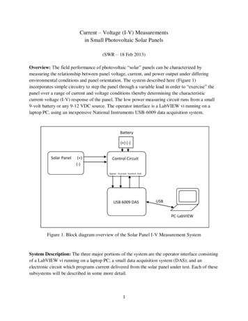
!5CONNECTOR SYSTEM FOR CONNECTING SOLAR PANELSThe Positive ( ) and Negative (-) outputs of a solar panel are fed through a watertight junction box. The appropriate wirelength is wired to the junction box for further connections. The solar panels supplied with these kits are provided withapproximately 2 ft. each of Positive and Negative wires that are pre-connected to the junction box. The free ends of thewires are terminated with a special mating type of connectors MC4 connectors) for ease in extending these wires forfurther connections.In this manual, the MC-4 Series will be used for explanations. Please do not cut off the solar panel connectors, orthe warranty will be voided.5.1. General Information on MC4 Connector SystemMC4 Connector System consists of male and female connectors. This type of connector system is easy to install anduses a “snap-in” type of safety locking clips to lock the two mating connectors, thereby avoiding unintentionaldisconnection. Also, the mating contacts are sealed against ingress of dust and water. Specifications are as follows: Contact diameter: 4 mmMaximum rated current: 30AMaximum system voltage: 1000VDegree of ingress protection when connected and properly locked: IP67Temperature range: 40 C to 90 CTÜV Rheinland approved5.2. MC4 Connectors (Fig. 5.2)The MC4 Connectors mentioned in this manual have been designated “Male” and “Female” ends based on thecharacteristics of the mating contact inserts inside the terminals.In the MC4 Male Connector (No.1 of Fig. 5.2), the internal mating contact insert (No.2 of Fig. 5.2) is a male pin. It hastwo slots (No.3 of Fig. 5.2) for insertion of the two “snap-in” types of locking tabs (No.6 of Fig. 5.2) of the MC4 FemaleConnector (No.4 of Fig. 5.2) for firm mating connection. This connector is marked "–".In MC4 Female Connector (No.4 of Fig. 5.2), the internal mating contact insert (No.5 of Fig. 5.2) is a female cylindricalsocket. It has two “snap-in” types of locking tabs (No.6 of Fig. 6.2) that are inserted into the two slots (No.3 of Fig. 5.2) inthe MC4 Male Connector (No.1 of Fig. 5.2) for firm mating connection. Wire is crimped to the contact inserts (2 and 5 ofFig. 5.2) using a special purpose-crimping tool designed for MC4 connectors. After the wire has been crimped, thecontact insert is required to be seated securely inside the housing and the strain relief/seal (No.7 of Fig. 5.2)13723!!46751. MC4 Male connector (marked “-”)2. Male contact insert3. Slots for accepting “snap-in” type of locking tabsof the mating MC4 female connector4. MC4 Female connector (marked “ ”)5. Female contact insert6. “Snap-in” type of locking tabs of the mating withthe slots on the MC4 male connector7. Strain relief and seal6Fig.5.2. MC4 Male and Female ConnectorsNote: Additional pairs of male/female MC4 connectors are also sold separately7
!5CONNECTOR SYSTEM FOR CONNECTING SOLAR PANELS (CONTINUED)5.3. Output Wires and Connections on the Solar PanelFig. 5.4 shows the output wires and connections of a solar panel. The output wires from the junction box of the solarpanel are terminated with the help of MC4 connectors. The Positive ( ) wire is terminated with a MC4 Female Connector(marked " ") and the Negative wire are terminated with a MC4 Male Connector (marked "-").Warning!When the surface of the solar panel/array is exposed to sunlight, a DC voltage appears at theoutput terminals turning it into a live voltage source. For example, a 24V nominal solar panel myput out an open circuit voltage of around 45VDC that may produce electrical shock. Multiple solarpanels connected in a series (to increase the output voltage) will put out higher lethal voltages.To avoid any electrical shock hazard during installation, make sure that the solar panel/array iscovered with an opaque (dark) material to block solar irradiation.5.4. Extending to the Output Wires of the Solar Panel (Fig. 5.4)Caution!Make sure to follow the polarity as marked on the outputcables from the solar panel junction box. This will avoidreverse polarities when mating extension cables. Male MC4 MatingConnector marked (-)Female MC4 Mating ConnectorPV Extension wireFemale MC4 matingConnector marked ( )Male MC4 Mating ConnectorPV Extension wireTo External PV circuit Fig 5.4. Connecting extension wires to the output wires of solar panel.1.2.3.The Positive ( ) wire of the solar panel is terminated with an MC4 Female Connector (marked “ ”). Connectthis cable to the MC4 Male Extension wire as shown in Figure 5.4. Make sure that the locking tabs “snap in” fora firm connection. The bare end of the Positive extension wire will now be of Positive polarity. Use a piece ofred sleeve or red tape near the bare end for identification as the Positive ( ) wire.The Negative (-) wire of the solar panel is terminated with a MC4 Male Connector (marked “-”). Connect thiscable to the MC4 Female Extension wire as shown in Figure 5.4. Make sure that the locking tabs “snap in” fora firm connection. The bare end of the Negative extension wire will now be of Negative polarity.Connect the two wires to the external PV circuit.Warning!Ensure that the polarity ( or -) of the wires is identified correctly before connecting toa circuit or a device. Damage due to wrong polarity may not be covered under warranty.!8
!5CONNECTOR SYSTEM FOR CONNECTING SOLAR PANELS (CONTINUED)5.5. Connecting Two Adjacent Solar Panels in Parallel (Fig. 5.5)MC4Y KitMC4 FemaleBranch Connector (-)10 ft. Female and Male MC4To external PV circuitMC4 Male BranchConnector ( )Fig. 5.5. Connecting two adjacent solar panels in parallel.Two or more solar panels can be connected in parallel to increase the current output while the output voltage remainsthe same. Fig. 5.5 above shows the arrangement for connecting two solar panels in parallel using the 10 ft. Female andMale MC4 wires and one MC4 Branch Connector Kit (MC4Y). This arrangement is applicable if the two solar panels areto be mounted adjacent to one another.The output wires of the two solar panels are first connected in parallel using the MC4 Male and Female BranchConnectors (MC4Y). The outputs of the Branch Connectors are then connected to the 10 ft. Female and Male MC4wires. The resulting output can be connected to charge controller or external PV circuit.5.6. Connecting Two Solar Panels in Parallel When Separated by Distance(Fig. 5.6)MC4Y KitExtension Cable:Sold separatelyMale MC4ConnectorMC4 FemaleBranch Connector (-)Adaptor KitTo externalPV circuitFemale MC4ConnectorMC4 Male BranchConnector ( )Fig. 5.6. Connecting two adjacent solar panels in parallel separated by an extended distance.9
!5CONNECTOR SYSTEM FOR CONNECTING SOLAR PANELS (CONTINUED)Fig. 5.6 above shows an arrangement for connecting two solar panels in parallel that are separated by an extendeddistance. In this case, the following will be required: Solar Extension Cables: 2 sets, sold separately as an optional item (Length to be determined).One MC4 Male Branch Connector and one MC4 Female Branch ConnectorSolar Adaptor Kit in pair (Length to be determined).In this case, the two optional Solar Extension Cables and the MC4 Connector Kit “MC4Y” are first used to bridge theextended distance between the panels. Then the Adaptor Kit is used to connect to the external PV circuit.Please note that this configuration will give you 10 ft. of wire length from solar panel to the charge controller or externalPV circuit. If you want additional length, you can add extension cables in between MC4Y kit and 10 ft. Adaptor Kit soldseparately.10
!6WIRINGCaution!The battery must be wired to the charge controller before the solarpanel is connected to the charge controller.!A pair of 10 ft. pre-assembled cables with Multi-Contact (MC) male and female connectors is provided primarily toconnect the solar panel to the charge controller. After making sure that sufficient length is available to wire the solarpanel to the charge controller, any excess wire may be used to wire the battery to the charge controller (tray cable).Renogy sell the try cables separately from the solar kits.6.1. Battery to Charge Controller Mark the cables to differentiate between Positive and Negative.Make sure the Positive terminal (marked ‘ ’) of the battery is connected to the Positive terminal (marked “BAT ”) of the charge controller and the Negative terminal (marked ‘-’) of the battery is connected to the Negativeterminal (marked “BAT -”) of the Charge Controller (Fig. 6.1.1). If you are not sure use a DC voltmeter todetermine the polarity of the battery bank. Reverse polarity connection will damage the Charge Controllerand the resulting damage will not be covered by warranty.We recommend to crimp the insulated fork terminals (not provided, Fig. 6.1.3) to one end of the Positive andNegative battery leads.Insert the fork terminals (Fig. 6.1.3) or screw the bare cables into the appropriate terminal on the chargecontroller: Positive lead is connected to the Positive terminal (marked “BAT ”) of the charge controller Negativelead is connected to the Negative terminal (marked “BAT -”) of the Charge Controller (Fig. 6.1.1).Crimp the battery ring terminals (Fig. 7.1.2) to the Positive and Negative wire leads to be connected to thebattery terminals.Clean the battery post terminals free of corrosion and other impurities.Bolt the ring terminals to the battery terminals making sure the correct polarity is observed.WarBe careful not to short theFig 6.1.2 Battery RingterminalPV PV-BAT BAT-Fig 6.1.3 Fork terminalDC DC-Fig 6.1.1. Typical PWM Solar Charge Controller (top view)connection terminals11
!6.2. Solar Panel to Charge Controller1.2.Determine the position of the solar panel. While positioning panels, avoid shading of the solar panel byneighboring obstacles such as vents, air-conditioners, TV antennas of RV roof. Position the panels to minimizewiring distance between the solar panel and the charge controller. Place the panel at least 8-10 inches awayfrom the roof edges and leave sufficient space to walk around the panel and access the mounting hardware.Make sure the thickness of the roof at the installation location is at least ½” thick and the material is strongenough to provide mechanical support to the solar panel and mounting hardware against possible windloading. Place the panel length-wise to reduce the effects of wind loading on the roof.MC4 Male connectorMC4 Female connectorFig. 6.2. PV extension wire3.4.5.(A) Two pre-assembled, 10 ft., AWG #12, Positive ( ) and Negative (-) PV extension wires have been providedfor solar kits below 300 Watt (see Fig. 6.2). The wires have MC4 mating connectors on one end for connectingto the solar panel and bare ends on the other side for connecting to the Charge Controller. The extensioncables should be marked ( ) and (-) to identify the polarity from the output cables of the solar panel.(B) Two 20 ft. AWG #12 solar extension cables with MC4 connectors on both ends and a pair of MC4 Adaptorkit will be provided for 400 Watt Solar Kit. The extension cables should be marked ( ) and (-) to identify thepolarity from the output cables of the solar panel.Please read sections 6.3 and 6.4 on connecting the extension wires to the panels.!WarAvoid sharp,6.7.ormaterial on the cable routeIt is better to crimp the bare end of the wires with the fork terminals (Fig 6.1.3).Insert the terminals into the appropriate terminal on the charge controller (Fig 6.1.1): Positive PV lead isconnected to the positive terminal (marked “PV ”) of the charge controller and the negative PV lead isconnected to the negative terminal (marked “PV -”) of the charge controller. Reverse polarity connection willdamage the Charge Controller and the resulting damage will not be covered by warranty.12
!7SOLAR PANEL INSTALLATION1.2.3.4.5.6.Stainless steel can be subject to a process called“thread galling” in which bolts can twist off and/orthe bolt threads seize to the nut’s thread. ApplyAnti-galling lubricant available at most hardwareor auto-part stores to all the stainless steelfasteners before installation. If anti-gallinglubricant is not available, any standard lubricantwill minimize the occurrence of “thread galling”.Fix the mounting brackets (Fig. 7.2) to the frameof the previously positioned solar panel using theslotted opening and the ¼”-20 x ¾" Flange Bolt,Nylon Locknut and flat washer (Fig. 8.1)Using a 7/16” wrench, tighten the nuts to securethe mounting brackets to the PV panel.Recommended tightening torque is 15 lbs.Position the panel with the attached mountingbrackets at the desired location and mark theposition of the desired mounting hole using asuitable marker by tracing the hole on themounting bracket. Please ensure that themounting surface is strong enough to support themounting hardware, solar panel, and wind loads.The end holes on the mounting brackets (Fig.7.2)are sized to accept the ¼” hardware supplied withthe unit.A Well-Nut is a bushing of tough neoprene rubberwith a flange at the top end and a captive brassnut mounted within the bore at the bottom end(Fig. 7.3). Tightening a conventional machine boltor screw engages the captive nut thereby causingthe bushing to expand outwards. This fastenssecurely to thinner roofs by bulging up and againstthe bottom surface of the roof (Fig. 7.6). If used ina blind hole in a solid surface material, the rubberwill expand outwards to create a secure fastening(Fig.7.7). The neoprene and brass resist mostenvironmental conditions. Additionally, the WellNut seals the drilled hole effectively against airand liquid leakage.!!!!!Solar Module1/4”-20x3/4” Flange bolt1/4” flat washerMounting bracket1/4” locknutRoofFig. 7.1. Attaching solar panel to 5-hole mounting bracket.1/4” holesFig. 7.2. Mounting bracket (Z Bracket).Flange1/2” Diameter1/4" Captive brass nutFig. 7.3. Construction of a Well-nut13
!7SOLAR PANEL INSTALLATION (CONTINUED)Typical Installation of a Well-NutFig. 7.4. Well-Nut is insertedinto a pre-drilled hole with itsflange against the outersurface. There is no need foraccess to the inner side.Fig. 7.5. The Z Bracket isplaced against the flange ofthe Well-Nut and is securedby the bolt engaging thecaptive brass nut.Fig. 7.6. As the bolt istightened, the neoprene bodyof the Well-Nut is compressedand expanded, forcing ittightly into the bolt’s threadsand against the inner surfaceof the thin RV roof material.Fig. 7.7. Installed in a blindhole in a solid material, thebody of the Well-Nut expandstightly against the walls of thehole, creating a secure,dependable fastening.7.To install the Well-Nuts, drill holes 1¼” deep at the marked positions using a ½” size drill bit. Make sure thatdrilling does not interfere with pre-existing wiring installations.8. Apply silicone or any appropriate sealant generously to the drilled holes for waterproofing.9. Insert the ¼” Well-Nut into the drilled holes so that only the flange section remains above the roof surface (Fig.7.4).10. Fasten the mounting brackets to the roof surface by inserting the ¼ x 1¼” serrated flange bolt into the Well-Nut(Fig. 7.5). Tighten using a 3/8” wrench to a recommended torque of 15 lbs. When the serrated flange bolt isscrewed into the Well-Nut, the material surrounding the well nut bulges slightly securing the structure to theroof (Fig. 7.6 & 7.8).Mounting Bracket1/4”-20x1¼” flange bolt¼” WasherSolar ModuleRoof material up toApprox. 3/8” thicknessWell-NutRubber bushing materialexpands when bolt is tightenedto securely anchor hardware.Fig. 7.8. Attaching the Z Bracket to the Roof14
!8CONNECTING TWO SOLAR PANELS IN PARALLEL1.2.3.4.If the existing panel is already connected to the mating connector on the pre-assembled cables provided in the original kit,remove this connection using tweezers or any other suitable tool.Connect the Positive leads (marked as ‘ ’) from the two solar panels to the suitable mating branch connector (as in Fig 8.1).Connect the Negative leads (marked as ‘-’) from the two solar panels to the suitable mating branch connector (as in Fig 8.1).Mate the MC branch connectors to the corresponding mating MC connector on the pre-assembled cables provided with youroriginal kit.MC4Y KitMC4 FemaleBranch Connector (-)10 ft. Long Extension CableTo external PV circuitMC4 Male BranchConnector ( )Fig. 8.1. Connecting solar modules in parallel.If the additional solar panels are required to bemounted at a distance from the existing solarpanel, a pair of cables with an MC4 connector,pre-assembled at one end, is provided.1.2.3.4.For this setup, an optional set of20MC4 wires that measure 20 ft. arerequired. It is optional to cut the pair ofcables to the appropriate length.In this case, once cable is cut, strip0.25" of the insulation at the blunt endsusing a suitable wire stripper.Crimp the male and female MC4connector to the blunt end of theappropriate cable with a suitable wirecrimping tool.Complete the connections as shown inFig. 8.2.MC4Y Kit20MC4 (2 sets)Male MC4ConnectorMC4 FemaleBranch Connector (-)10 ft. Femaleand Male MC4To externalPV circuitFemale MC4ConnectorMC4 Male BranchConnector ( )Fig. 8.2. Connecting solar modules in parallel with additional module.15
!9CONNECTING MULTIPLE SOLAR PANELS IN PARALLEL9.1 Connecting Three Adjacent Solar Panels in Parallel12AMC4Y KitMC4 FemaleBranch Connector (-)3Optional Solar Cablewith MC4 Female andMale ConnectorsBMC4 Male BranchConnector ( )MC4Y KitMC4 FemaleBranch Connector (-)10 ft. Female and Male MC41.5’ Solar Cable withMC4 Female andMale ConnectorsTo externalPV circuitMC4 Male BranchConnector ( )Fig. 9.1 Connection of three solar panels in parallelThree solar panels can be connected in parallel to increase the current output while the output voltage remains thesame. Fig. 9.1 above shows the arrangement for connecting three solar panels in parallel using the following: Four 1.5’ Solar Cables with MC4 Female and Male ConnectorsTwo pairs of MC4 Branch Connector Kit (MC4Y)Two 20MC4 CablesThis arrangement is applicable if the three solar panels are to be mounted adjacent to each other.ConnectionsThe output wires of solar panels no. 1 and 2 from Figure 10.1 are first connected in parallel with one pair of MC4 Maleand Female Branch Connectors (MC4Y, labeled ‘A’). The ends these Branch Connectors are then connected to two 1.5’Solar Cables with Male and Female ends. Similarly, the ends of the solar panel no. 3 connect to two 1.5’ Solar Cableswith Male and Female ends. Making these connections will result in a pair of Positive ( ) and Negative (-) outputs shownin Figure 9.1 in red and black dashed lines respectively. These outputs are then connected to a second pair of MC416
!Male and Female Branch Connectors (MC4Y, labeled ‘B’). Finally, t
panel and the storage batteries. The solar charge controller will ensure that your battery is charged with the appropriate amount of solar power, as per the battery manufacturer’s recommendations. The solar charge controller comes with eight selectable charging pr