Transcription
Technical Service InformationVW/AUDI/MINI 09G/09M/TF60-SNPRELIMINARY INFORMATIONThe Japanese automatic transmission manufacturer AISIN Co., LTD is the developer of the FWD TF60-SNTransmission, a 6 speed fully automatic and computer controlled transmission. Vehicle applications known atthe time of printing is as VWA2A4TTMini ClubmanMini ran (Non 2003-On2006-On2.0L2.0L1.8L1.6L1.6L"1.4, 1.6, 2.0L""1.6, 1.9, 2.0L""1.8, 1.9, 2.0, 2.5L""2.0, 3.2L""1.9, 2.0, 2.5L"2.0L"1.4, 2.0L""1.6, 1.9, 2.0L"3.6L09G (TF-60SN)09G (TF-60SN)09G (TF-60SN)09G (TF-60SN)09G (TF-60SN)09G (TF-60SN)09G (TF-60SN)09G (TF-60SN)09G (TF-60SN)09G (TF-60SN)09G (TF-60SN)09G (TF-60SN)09G (TF-60SN)09G (TF-60SN)09M (TF-60SN)When Volkswagen engineers developed the transmission in conjunction with Aisin and adapted it toVolkswagen vehicles they gave it the 09G/09M designation.This transmission is very similar to the AF40-6 transmission but with two very significant differences. One isthe B1 brake band has been eliminated and replaced with a B1 Clutch Pack. The other is the rear cover that gaveaccess to the C/K2 clutch has been eliminated.As a result of this transmission being used in a variety of applications, the number of friction plates in a clutchpack will vary depending upon torque load.It uses the Lepelletier planetary system and is gear ratio sensitive requiring correct transmission interchange.The advantage of this Lepelletier arrangement is its simple, space-saving and lightweight design. lt combines asimple planetary gearset with a subsequent Ravigneaux arrangement. This makes six speeds possible with onlyfive shifting elements.The computer controls both shift timing and shift feel with the use of solenoids. The computer monitors gearratio through the Input and Output shaft Hall Affect Speed Sensors. It also can determine the rate of change andadapt the shifts as friction elements wear.13-13AUTOMATIC TRANSMISSION SERVICE GROUPPage 1 of 29
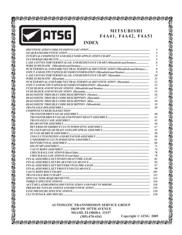
Technical Service InformationSelector LeverThe appearance of the selector lever may vary for different vehicles however, the operation and the functionremains the same with the use of the TF60-SN.The steering wheel paddles are available as options and it too can vary in appearance with differentvehicles.Selector Lever Positions and OperationP - ParkBefore the selector lever can be moved out of thisposition, the ignition must be switched on and the footbrake must be pressed. Additionally, the lockingbutton on the selector lever must be pressed.Lock ButtonR - ReverseTo shift into this gear, the locking button must bepressed.N - NeutralThe transmission is in idle in this position. If theselector lever is in this position for a long time and thevehicle is driven at less than 3 mph (5 km/h), the footbrake must be pressed again to leave this position.D - DriveThumb PaddlesDownshift Button(E439)Upshift Button(E438)In this position, the forward gears are shiftedautomatically.S - SportThe locking button must be pressed to shift into theselection range “S.” The control module selects gearsautomatically according to a “sporty” characteristiccurve.- ATSG and The Tiptronic functions are performed in the rightselector gate and at the steering wheel paddles.Copyright 2013 ATSGFigure 1AUTOMATIC TRANSMISSION SERVICE GROUP13-13Page 2 of 29
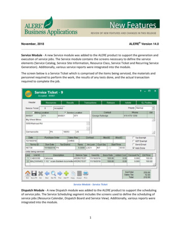
Technical Service InformationTiptronic Upshift (E438) and Downshift(E439) Buttons on Steering WheelThese operational buttons are found in the steeringwheel on the left and right side.Upshifting and downshifting occurs by operatingthese buttons. The shift signals are an input to theTransmission Control Module (TCM - J217) which inturn controls the shifting of the transmission.Signal UtilizationIf the Tiptronic buttons in the steering wheel areoperated in automatic mode, the transmission controlenters Tiptronic mode. If the buttons are not operated,the transmission control returns to automatic modeafter a predetermined amount of time.Effect of Signal FailureIn case of a signal failure, no Tiptronic functions arepossible using the steering wheel buttons.Tiptronic Shifting Strategy- Automatic upshifting when maximum RPM isreached.- Automatic downshifting when the RPM’s fallbelow the minimum RPM.- Kick down downshifting- Acceleration from standstill in second gear byselecting 2nd before accelerating.The driving conditions, as well as driving resistancesuch as climbing hills, or road profile as in curves andthe driver type meaning the manner in which thedriver is driving the car are all evaluated by the TCMand adapts accordingly.The basic parameters for the calculation of gearselection have not fundamentally changed comparedto previous automatic transmissions. Due toconstantly increasing integration of the transmissioncontrol with other vehicle systems such as the engine,ESP, or the steering angle, a large amount ofinformation is available to better define the currentdriving conditions and the driving manner.Sport Mode “S”A performance oriented shifting program is availableto the driver in selector lever position “S”.If the TCM recognizes the selector lever in the “S”position, the shifting characteristic curves arereallocated to higher engine speeds. This increasesthe driving dynamic.The DSP also adapts to driver input (driver typeevaluation) and driving situations in the “S” position.The “S” mode contains the following characteristics:- If the selector is placed in “S” while driving with anunchanging accelerator pedal position, a downshiftoccurs within defined limitations.- To achieve a more direct reaction to the movementsof the accelerator pedal, the torque converter lock-upclutch applies as soon as possible.- Upshift prevention or downshift prevention.Dynamic Shifting Program (DSP)This automatic transmission has the latest generationDynamic Shifting Program DSP.Copyright 2013 ATSGFigure 2AUTOMATIC TRANSMISSION SERVICE GROUP13-13Page 3 of 29
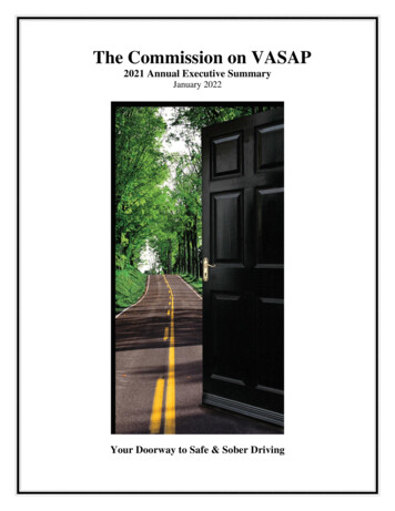
Technical Service InformationEmergency ModeIn mechanical emergency running mode, 3rd gear isalways engaged.4050System pressure is controlled to the maximum value;the shifting elements are pressurized to maximumshifting pressure. This results in a hard shift whenengaging the driving mode.The torque converter lock-up clutch remains off.30PRNDS201060Reverse gear is available (R-gear locking is notactive).6050If the transmission is already in 4th, 5th or 6th gear,the current gear is maintained until the selector leveris placed into the neutral position or immediately afteran ignition cycle.When starting off, 3rd gear is always engagedwhether the selector lever is in the D or S position.70401/2905013001/10Operating Ranges of the Torque ConverterLock-Up ClutchDepending on driving mode, engine load and vehiclespeed, the torque converter lock-up clutch is firstregulated with a minimal slip and subsequentlycompletely applied.During regulated operation, fuel consumption isreduced compared to a released torque converterlock-up clutch and drive comfort is improvedcompared to a fully applied clutch.TowingWhen towing, the ATF pump is not operated, andtherefore rotating components are not lubricated.To avoid severe damage to the transmission, thefollowing conditions must be met:- The selector lever must be in the “N” Neutralposition.- Towing speed must not exceed 31 mph (50 km/h).Using Tiptronic in “S” mode, the torque converterlock-up clutch is applied as soon as possible. Thedirect power connection between engine andtransmission improves sporty driving feel.In a climbing mode, the torque converter lock-upclutch applies in 2nd gear.When ATF temperature is above 130º C, the regulatedapply feature is prohibited and an immediate applyoccurs. This helps the ATF maintain a lower thermalload and cools it down.For Jetta and Passat, if the battery is disconnected ordischarged, the selector lever emergency release mustbe operated to shift the selector lever out of “P” into“N”.Engine Load- Vehicle must not be towed further than 31 miles (50km).TCC - OFFRegulatedTCC ApplyFully AppliedTCCVehicle SpeedCopyright 2013 ATSGFigure 3AUTOMATIC TRANSMISSION SERVICE GROUP13-13Page 4 of 29
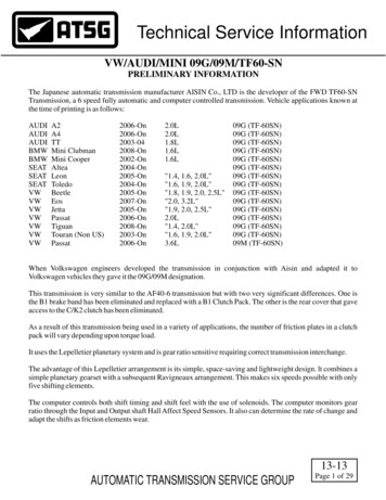
Technical Service InformationCOMPONENT APPLICATION CHARTK3K1Clutch ClutchB1ClutchF1 RollerClutchB2K2Clutch ClutchCLUTCH APPLICATION CHARTGear1st Gear2nd Gear3rd Gear4th Gear5th Gear6th GearRev GearK-1K-2K-3B-1B-2Clutch Clutch Clutch Clutch *OnOnOnF-1Torque EngineEngine1.8L,Roller Conv. 1.6L, 2.0LClutch Clutch Ratio*** 90.8590.6863.3940.8520.6763.193* The B-2 Clutch is applied in "Tiptronic Mode" 1st gear, only for engine braking.** During normal driving operation, the Torque Converter Clutch can be applied in each gear.*** Transaxle Codes (GSY 1.6L) and (GJZ 2.0L).**** Transaxle Code (FXA 1.8L).Transfer Gear Ratio, Codes GSY, GJZ, FXA, (Driven 52T/Drive 49T) Ratio 1.061Final Drive Gear Ratio, Codes GSY, FXA, (15T/61T) Ratio 4.067Final Drive Gear Ratio, Codes GJZ, (15T/58T) Ratio 3.867Copyright 2013 ATSGFigure 4AUTOMATIC TRANSMISSION SERVICE GROUP13-13Page 5 of 29
Technical Service InformationSOLENOID LOCATIONSN91(#4 Sol.)N93(#6 Sol.)N92(#5 Sol.)N282(#9 Sol.)N283(#10 Sol.)N90(#3 2 Sol.)9173 T5DCB6A09064FBX6A08574EON88(#1 Sol.)SOLENOID AND CLUTCH APPLICATION CHARTSolenoid Shift SequenceClutch Application ChartGearShiftPositionParkNeutralReverse1st Gear2nd Gear3rd Gear4th Gear5th Gear6th oToToToPressure Control SolenoidsN92 N282 N90 N283 N93 N91SV-5 SV-9 SV-3 SV-10 SV-6 SV-4OFF OFFONON PWMONONONON PWMONONOFF ON PWMOFF ONONON PWMOFF ONONOFF PWM PWMOFF ONOFF ON PWM PWMOFF OFF ONON PWM PWMONOFF OFF ON PWM PWMONOFF ONOFF PWM PWMT On in Tiptronic ModeTo Solenoid is toggled On to OffClutch and FreewheelComponentsK1K2K3B1ONONONONONONON ONON ONONONB2F1ONONCopyright 2013 ATSGFigure 5AUTOMATIC TRANSMISSION SERVICE GROUP13-13Page 6 of 29
Technical Service InformationPressure TapsK1K2LubeB2TCC Release2400. 75402024330aK3Copyright 2013 ATSGFigure 6AUTOMATIC TRANSMISSION SERVICE GROUP13-13Page 7 of 29
Technical Service InformationPressure TapsLubeB1LINE PRESSURE SPECIFICATIONS"Observed" Pressure SpecificationsMany Thanks To;Jesse ZachariasFor Providing UsWith These SpecsTo ShareSelectorLever"D" Idle"D" Idle (Tiptronic)"D" Stall*"D" Stall (Tiptronic)*"R" Idle"R" Stall*TapsRequiredK1 & B2K1 & B2K1 & B2K1 & B2K3 & B2K3 & B2Specifications in 580-8580-85270-275270-275* "D" & "R" Stall, at approx 2300 rpm, the PCM cuts fuel to engine.Other "Observed" PressuresLube Pressure 4-8 psi, 8-10 psi in 6th gearTCC Release 80-90 psi in Reverse"Observed" K1 and K2 Pressures, at operating temperature with a new valve body installed.Initial engagement N to D; K1 pressure at idle is 56-60 psi.Under acceleration in D; K1 pressure is 75-80 psi.Before the 1-2 shift in D; K1 pressure raises to 140-150 psi.When shift is completed; K1 pressure settles at 80-90 psi in 2nd gear.Before the 2-3 shift in D; K1 pressure raises to 95-100 during 2-3 shift and settles at 70 psi in 3rd.Before the 3-4 shift in D; K1 pressure raises to 140 psi, K2 pressure still under 4 psi. Then K1 pressure begins to dropand K2 pressure begins to rise with both settling at 85-90 psi in 4th gear.During 4-5 shift in D; K2 pressure raises to 190-200 psi, K1 pressure raises to 155-160 psi, then K1 drops to 40 psi,(While K2 is 170), then drops gradually to less than 2 psi, and K2 settles at 140 psi in 5th gear.During 5-6 shift in D; K2 pressure drops to 110-120 in 6th gear.Copyright 2013 ATSGFigure 7AUTOMATIC TRANSMISSION SERVICE GROUP13-13Page 8 of 29
Technical Service InformationINTERNAL HARNESSWiring Harnessfrom 8 terminalCase Connector(ISS, OSS & 90649173T5GAU6A06894EOOSS BlueClip Connector(G195)ISS WhiteClip Connector(G182)TransmissionFluid Temp. Sensor(G93)Wiring Harnessfrom 14 terminalCase Connector(All Solenoids)ISS G182The Transmission Input Speed Sensor is a Hall Affect that produces a signal from the lugs of the K2 ClutchDrum. The TCM uses this information to control adaptation and gear monitoring. Should this sensor fail, theEngine RPM sensor is use as a back up. Lock-up clutch apply strategy may be affected.OSS G195The Transmission Output Speed Sensor is a Hall Affect that produces a signal from the lugs on the Parking Gear.The TCM uses this information for the Dynamic Shifting Program (driving condition evaluation), vehiclespeed, shift points and gear monitoring. Should this sensor fail, the speed signal from the ABS Control Module isused as a back up.TFT G93Transmission fluid temperature is used to influence main line pressure and converter clutch strategies. Areplacement value is taken from the ECT should this sensor fail. TCC and adaptations usually cease whichCopyright 2013 ATSGtypically leads to harder shifting.Figure 8AUTOMATIC TRANSMISSION SERVICE GROUP13-13Page 9 of 29
Technical Service InformationSOLENOID IDENTIFICATIONN91(#4 Sol.)N93(#6 Sol.)N92(#5 Sol.)N282(#9 Sol.)N283(#10 Sol.)N90(#3 090649173T5HydraulicPressureSender # 2(G194)GAU6A06894EOHydraulicPressureSender # 1(G193)N89(#2 Sol.)N88(#1 Sol.)Hydraulic Pressure Senders G193 and G194The G193 and G194 are Normally Open transducers which closes when the K1or the B2 clutch circuit ischarged. The G193specifically monitors the K1 clutch while the G194 monitors the B2 clutch. The use of theseswitches were eliminated in June of 2004.N88 and N89Solenoid 1 (N88) and 2 (N89) are Normally Closed On/Off Solenoids and are used to control shifting of gears 4through 6 and are sporadically and alternately activated during gear shifting. They are also used to control theB2 Brake apply in 1st gear Tiptronic mode for engine breaking.N90, N91, N92, N93, N282 and N283Solenoid N92 controls the K1 clutch, Solenoid N91 controls the lock-up clutch apply in the torque converter,Solenoid N90 controls K3 clutch apply, Solenoid N93 regulates main line pressure, N282 controls K2 clutchapply and N283 controls the B1brake clutch apply.Copyright 2013 ATSGFigure 9AUTOMATIC TRANSMISSION SERVICE GROUP13-13Page 10 of 29
Technical Service InformationSOLENOID CASE CONNECTOR1314121086411975312View looking into the 14 terminal transmission case connectorSolenoidNumber(Name)Positive Meter LeadNegative Meter LeadResistanceTerminal # (Wire Color)Terminal # (Wire Color)(Ω Ohms)Solenoid # 1(N88)1(White)Case Ground10.0 - 16.0Solenoid # 2(N89)2(Black)Case Ground10.0 - 16.0Solenoid # 3(N90)7(Lt. Blue)8(Lt. Green)4.0 - 8.0Solenoid # 4(N91)11(Lt. Green)12(Brown)4.0 - 8.0Solenoid # 5(N92)3(Yellow)4(Purple)4.0 - 8.0Solenoid # 6(N93)13(Green)14(Grey)4.0 - 8.0Solenoid # 9(N282)5(Red)6(Blue)4.0 - 8.0Solenoid # 10 (N283)9(White)10(Black)4.0 - 8.0The internal wire colors are provided in the chart above.Copyright 2013 ATSGFigure 10AUTOMATIC TRANSMISSION SERVICE GROUP13-13Page 11 of 29
Technical Service InformationTFT AND RPM SENSOR CONNECTOR86475312View looking into the 8 terminal transmission case connectorSensorID(Name)Positive Meter LeadNegative Meter LeadResistanceTerminal # (Wire Color)Terminal # (Wire Color)(Ω Ohms)37.0 - 51.0 K Ω @ -30º C5.0 - 8.0 K Ω @ 10º CTFT (G93)1(Orange)2(Orange)3.0 - 5.0 K Ω @ 25º C230 - 265 Ω @ 110º C100 - 120 Ω @ 145º CISS(G182)3(White)4(Red)5.0 M Ω*OSS (G195)5(Tan)6(Blue)5.0 M Ω*PS1(G193)7(N/A)**Case GroundOpenPS2(G194)8(N/A)**Case GroundOpenThe internal wire colors are provided in the chart above.*The ISS and OSS are Hall Affect Sensors and should be checked using a scope under operatingconditions. The resistance values provided in the chart above came from new sensors. Resistancechecks of these type of sensors at best would inform you of either open or grounded circuits withinthe sensor itself.** Pressure Switches 1 and 2 are not from June 2004 and up. These are normally open switches andclose when their respective circuits are charged.Copyright 2013 ATSGFigure 11AUTOMATIC TRANSMISSION SERVICE GROUP13-13Page 12 of 29
Technical Service Information8 Terminal Trans.Case Conn.5TCMJ217OSS63ISSTypical VW Wiring38 SP 14 Terminal Trans.Case Conn.N8850 SP51 NIN 439 NIN-145 TFT S1411N89TFT SensorS2287824 Press. Sw. 125 Press. Sw. 2152TFT N90Some ModelsS3 307S3 -188N91Gear LeverPosition SensorS4 511S4 -4312198473621522S5 33710S5 -44TiptronicSwitchN92N9348Data BUS On Board Diag. InterfaceS6 3113S6 -171446 CAN-HCAN Communication34 CAN-LPowerSupplyRelayFuse27 IGN28 IGN3FuseN282S9 165S9 -326N283S10 49S10 -4410B 21GNDBatteryCopyright 2013 ATSGFigure 12AUTOMATIC TRANSMISSION SERVICE GROUP13-13Page 13 of 29
Technical Service InformationTCM J217 CONNECTOR IDView looking into the TCM (J217)132456789 10 11 12 13 1415 16 17 18 19 20 21 22 23 24 25 26272829 30 31 32 33 34 35 36 37 38 39 4041 42 43 44 45 46 47 48 49 50 51 52View looking into the 52 pin J217 connectorSolenoidNumber(Name)Positive Meter LeadNegative Meter LeadResistanceTerminal # (Wire Color)Terminal # (Wire Color)(WOhms)Solenoid # 1(N88)41(Black/Violet)1or2(Brown)10.0 - 16.0Solenoid # 2(N89)15(Black/Grey)1or2(Brown)10.0 - 16.0Solenoid # 3(N90)30(Yellow/Violet)18(Yellow/Green)4.0 - 8.0Solenoid # 4(N91)543(Yellow/Blue)4.0 - 8.0Solenoid # 5(N92)42(White/Violet)6(Violet/Green)4.0 - 8.0Solenoid # 6(N93)31(Grey)17(Green/Grey)4.0 - 8.0Solenoid # )(Blue)44(Violet/Yellow)4.0 - 8.0Solenoid # 10 (N283)4TFT (G93)45(Violet)8ISS(G182)51(White)39(Brown)5.0MOSS )Open(Violet/White)4.0 - 8.0See chart P.12External harness wire colors are provided in the chart above and may vary depending on year, makeand model of vehicle.Figure 1313-13AUTOMATIC TRANSMISSION SERVICE GROUPPage 14 of 29
Technical Service InformationPASSAGE ID- HEAT EXCHANGER ATTACHEDTO THE TRANSMISSION CASEPump InletPump OutletBlocked by PumpB1Front PlanetLube (1)K1 K3TCC ReleaseCooler ReturnTo VB (8)Through PumpTCC ApplyTo Coolerfrom VB (1)Differential LubeFrom VB (1)Case passage IDwith the heatexchangerattached to thetransmissionTCC Release Pressure TapB2LubeK2K1 Pressure TapTo B1 Pressure TapCooler ReturnTo VB (5)Through PumpCooler ReturnTo VB (6)Through PumpTCC ApplyFrontPlanetLube(3)TCC ReleaseK3K1B1Pump OutletPump InletFigure 14AUTOMATIC TRANSMISSION SERVICE GROUPCopyright 2013 ATSG13-13Page 15 of 29
Technical Service InformationPASSAGE ID- COOLER SEPARATE FROM THETRANSMISSION CASEPump InletPump OutletBlocked by PumpB1Front PlanetLube (1)K1 K3TCC ReleaseExternal CoolerReturnTo VB (2)TCC ApplyTo ExternalCooler from VB (1)Cooler LubeFilterCase passage IDwith the heatexchanger(cooler) separatefrom thetransmissionDifferential LubeFrom VB (1)TCC Release Pressure TapB2LubeK2K1 Pressure TapTo B1 Pressure TapTo External CoolerThrough Pump (6)Cooler ReturnTo VB (6)Through PumpTCC ApplyFrontPlanetLube(3)TCC ReleaseK3K1B1Pump OutletPump Inlet Copyright 2013 ATSGFigure 15AUTOMATIC TRANSMISSION SERVICE GROUP13-13Page 16 of 29
Technical Service InformationVW TECHNICAL DATAManufacturerAISIN Co., LTD. JapanTransmission TypeElectro-hydraulically controlled 6-speed planetary gear withhydrodynamic torque converter and traction controlled torqueconverter lock-up clutch for front wheel drive and transverse installation.ControlHydraulic control module (Valve Body) in oil sump with an externalelectronic control module.Dynamic Shifting Program (DSP) with separate Sport program in“Position S” and the Tiptronic shifting program for manual gearchange (optional with Tiptronic steering wheel)Torque PerformanceUp to 332 lbs-ft (450 Nm), depending on versionIntermediate drivefor code lettersGSY/GJZNo. of teeth 52/49 1.061Final Drive GSYNo. of teeth 61/15 4.067Final Drive GJZNo. of teeth 58/15 3.867ATF SpecificationG 052 025 A2Filing amount7.4 quarts (7.0 liters) [initial fill] lifetime fillingWeightApproximately 182 lbs. (82.5 kg).LengthApproximately 13.8 inches (350 mm)Spread6.05Depending on engine type, overall ration is configured as 5 E transmission or as a 6 speed transmissionFor the 5 E transmission, the highest speed is reached in 5th gear. The 6th gear reduces engine speed,improves driving comfort and reduces fuel consumption:For the 6 speed transmission configuration, the higest speed is reached in 6th gear. The 6th gear lowerstransmission gear ratio and increases driving dynamics.Copyright 2013 ATSGFigure 1613-13AUTOMATIC TRANSMISSION SERVICE GROUPPage 17 of 29
Technical Service InformationFLUID LEVEL CHECKSCheck andFill PlugFluid LevelStand PipeCopyright 2013 ATSGFigure 17AUTOMATIC TRANSMISSION SERVICE GROUP13-13Page 18 of 29
Technical Service Information"09G" VALVE BODY EXPLODED 9250251252254300LOWER V.B. TO ACCUMULATOR HOUSING 2 BOLT (70 MM LENGTH).LOWER V.B. TO UPPER V.B. BOLT (39.5 MM LENGTH).LOWER V.B. TO UPPER V.B. BOLT (28 MM LENGTH).ACCUMULATOR-1 HOUSING TO UPPER V.B. (64 MM LENGTH)(3 REQ).ACCUMULATOR-1 HOUSING TO UPPER V.B. (52 MM LENGTH)(4 REQ).ACCUMULATOR-2 HOUSING TO UPPER V.B. (52 MM LENGTH)(4 REQ).ACCUMULATOR-2 HOUSING TO UPPER V.B. (64 MM LENGTH)(2 REQ).ACCUMULATOR-1 HOUSING ASSEMBLY.ACCUMULATOR-1 ASSEMBLY SPACER PLATE.ACCUMULATOR-2 HOUSING ASSEMBLY.ACCUMULATOR-2 ASSEMBLY SPACER PLATE.UPPER V.B. TO LOWER V.B. BOLTS (21 MM LENGTH)(10 REQUIRED).UPPER VALVE BODY ASSEMBLY.LOWER VALVE BODY ASSEMBLY.MAIN VALVE BODY SPACER PLATE.300254Copyright 2013 ATSGFigure 1813-13AUTOMATIC TRANSMISSION SERVICE GROUPPage 19 of 29
Technical Service Information"09G" LOWER VALVE BODY ASSEMBLY, EXPLODED 275LOWER VALVE BODY ASSEMBLY.PRESSURE SWITCH ASSEMBLY (2 REQUIRED).N91, PWM CONVERTER CLUTCH SOLENOID.N93, PWM LINE PRESSURE CONTROL SOLENOID.N92, PWM K1 CLUTCH CONTROL SOLENOID.N282, PWM K2 CLUTCH CONTROL SOLENOID.N283, PWM B1 CLUTCH CONTROL SOLENOID.N90, PWM K3 CLUTCH CONTROL SOLENOID.PWM SOLENOID RETAINING PINS (6 REQUIRED)K1 CLUTCH REGULATOR VALVE.K1 CLUTCH REGULATOR VALVE SPRING.K2 CLUTCH REGULATOR VALVE.K2 CLUTCH REGULATOR VALVE SPRING.B1 CLUTCH REGULATOR VALVE.B1 CLUTCH REGULATOR VALVE SPRING.K3 CLUTCH REGULATOR VALVE.K3 CLUTCH REGULATOR VALVE SPRING.N91 AND N93 SOLENOID PIN RETAINING BRACKET.SOLENOID PIN RETAING BRACKET BOLT.TRANSAXLE FLUID TEMPERATURE SENSOR RETAINING BRACKET.TFT SENSOR RETAINING BRACKET BOLT.SOLENOID PIN RETAINING BRACKET BOLTS (2 85286287288289290291292N92, N282, N283, N90 SOLENOID PIN RETAINING BRACKET.MANUAL VALVE.PRIMARY PRESSURE REGULATOR VALVE.PRIMARY PRESSURE REGULATOR VALVE SPRING.PRIMARY PRESSURE REGULATOR BOOST VALVE.PRIMARY PRESSURE REGULATOR BOOST VALVE SLEEVE.PRIMARY REGULATOR BOOST SLEEVE RETAINER.N88, ON/OFF SOLENOID.SOLENOID RETAINING BOLT (2 REQUIRED).N89, ON/OFF SOLENOID.SECONDARY PRESSURE REGULATOR VALVE.SECONDARY PRESSURE REGULATOR SPRING.SECONDARY PRESSURE REGULATOR BORE PLUG.SECONDARY PRESSURE REGULATOR BORE PLUG RETAINER.SOLENOID MODULATING VALVE A FOR N88, N89, N90, N282, N283.SOLENOID MODULATING VALVE A SPRING.SOLENOID MODULATING VALVE A SPRING RETAINER.Copyright 2013 ATSGFigure 19AUTOMATIC TRANSMISSION SERVICE GROUP13-13Page 20 of 29
Technical Service Information"09G" LOWER VALVE BODY SMALL PARTS, EXPLODED VIEW7091252300298ENLARGED 95296297298299UPPER VALVE BODY ASSEMBLY.LOWER VALVE BODY ASSEMBLY.CHECK VALVE 2: LUBE (.392" DIAMETER).CHECK VALVE 2 SPRING.CHECK VALVE 3: FWD ENG./K1/K2 REG VALVE FEED (.313" DIAMETER).CHECK VALVE 3 SPRING.PLASTIC CHECK VALVE 1: K2CHECK VALVE 4: FWD ENG. ACCUM. EXHAUST (.392" DIAMETER).CHECK VALVE 4 SPRING.300301302303304MAIN VALVE BODY SPACER PLATE.CHECK VALVE 5: B2 ORIFICE CONTROL- REVERSE (.313" DIAMETER).CHECK VALVE 5 SPRING.CHECK VALVE 1: LUBE & COOLER (.392" DIAMETER).CHECK VALVE 1 SPRING.Figure 20AUTOMATIC TRANSMISSION SERVICE GROUPCopyright 2013 ATSG13-13Page 21 of 29
Technical Service InformationLOWER VALVE BODY CHECK VALVE AND VALVE SPRING SPECS264. K1 RegulatorValve Spring266. K2 RegulatorValve SpringNo. Coils-10Overall Length-.710"Outside Diameter- .325"Coil Diameter- .035"Color- Lt. PinkNo. Coils-11Overall Length-.740"Outside Diameter- .260"Coil Diameter- .040"Color- White279. Primary PressureRegulator Valve Spring268. B1 RegulatorValve Spring270. K3 RegulatorValve SpringNo. Coils-9Overall Length-.745"Outside Diameter- .252"Coil Diameter- .038"Color- RedNo. Coils-10Overall Length-.815"Outside Diameter- .325"Coil Diameter- .040”Color- none287. Secondary PressureRegulator Valve Spring291. Solenoid ModulatorValve A SpringNo. Coils-9Overall Length-1.440"Outside Diameter- .524"Coil Diameter- .045"Color- PinkNo. Coils-13Overall Length-1.500"Outside Diameter- .424"Coil Diameter- .045"Color- WhiteNo. Coils-10Overall Length-1.000"Outside Diameter- .315"Coil Diameter- .040”Color- White294. Check Valve 2Spring296. Check Valve 3SpringNo. Coils-8Overall Length-.560"Outside Diameter- .250"Coil Diameter- .040"Color- Lt. BlueNo. Coils-10Overall Length-.380"Outside Diameter- .163"Coil Diameter- .016”Color- Red302. Check Valve 5Spring299. Check Valve 4SpringNo. Coils-8Overall Length-.628"Outside Diameter- .251”Coil Diameter- .035"Color- White304. Check Valve 1SpringNo. Coils-10Overall Length-.380"Outside Diameter- .163"Coil Diameter- .016”Color- RedNo. Coils-12Overall Length-.595"Outside Diameter- .250"Coil Diameter- .025”Color- OrangeCopyright 2013 ATSGFigure 2113-13AUTOMATIC TRANSMISSION SERVICE GROUPPage 22 of 29
Technical Service Information"09G" UPPER VALVE BODY ASSEMBLY, EXPLODED 0UPPER VALVE BODY ASSEMBLY.MAIN VALVE BODY SPACER PLATE.TCC SWITCH VALVE.TCC SWITCH VALVE SPRING.TCC SWITCH VALVE SPRING RETAINER.PRESSURE MODIFIER VALVE BORE PLUG RETAINER.PRESSURE MODIFIER VALVE STEEL BORE PLUG.PRESSURE MODIFIER VALVE SPRING.PRESSURE MODIFIER VALVE.K3 RELAY VALVE BORE PLUG RETAINER.K3 RELAY VALVE STEEL BORE PLUG.K3 RELAY VALVE.K3 RELAY VALVE SPRING.B2 RELAY VALVE (M1) SPRING RETAINER.B2 RELAY VALVE (M1) SPRING.Br YELAY VALVE (M1).SCREEN FOR MODULATING VALVES A & B.RELAY VALVE PLUG.RELAY VALVE.RELAY VALVE SPRING.RELAY VALVE SPRING RETAINER.B1 SWITCH VALVE BORE PLUG RETAINER.B1 SWITCH VALVE BORE PLUG.B1 SWITCH VALVE.B1 SWITCH VALVE 3403413423433443453463474-5 TIMING VALVE BORE PLUG RETAINER.4-5 TIMING VALVE STEEL BORE PLUG.4-5 TIMING VALVE.4-5 TIMING VALVE SPRING.K2 RELAY VALVE RETAINER.K2 RELAY VALVE BORE PLUG.K2 RELAY VALVE.K2 RELAY VALVE SPRING.K1 RELAY VALVE RETAINER.K1 RELAY VALVE BORE PLUG.K1 RELAY VALVE.K1 RELAY VALVE SPRING.B2 SWITCH VALVE BORE PLUG RETAINER.B2 SWITCH VALVE STEEL BORE PLUG.B2 SWITCH VALVE.B2 SWITCH VALVE SPRING.B2 SWITCH VALVE TIPTRONIC M1 BORE PLUG RETAINER.B2 SWITCH VALVE TIPTRONIC M1 BORE PLUG.B2 TIPTRONIC M1 VALVE.Copyright 2013 ATSGFigure 22AUTOMATIC TRANSMISSION SERVICE GROUP13-13Page 23 of 29
Technical Service Information"09G" UPPER VALVE BODY SMALL PARTS, EXPLODED VIEWENLARGED VIEW354252 (ACCUMULATOR SIDE)7091300351350319ENLARGED VIEW352353349348252(MAIN SPACER SIDE)252300319348349350351352353354UPPER VALVE BODY ASSEMBLY.MAIN VALVE BODY SPACER PLATE (MODEL SENSITIVE).PLASTIC FILTER FOR SOLENOID MODULATING VALVES A & B.PLASTIC VALVE CHECK VALVE 2: SECONDARY PR VALVE.PLASTIC CHECK VALVE 4: K1CHECK BALL 1, 5.3 MM (.210") DIAMETER.CHECK VALVE 6: MANUAL VALVE (.392" DIAMETER).CHECK VALVE 6 SPRING.PLASTIC CHECK VALVE 3: B.PLASTIC CHECK VALVE 5: K3.Copyright 2013 ATSGFigure 23AUTOMATIC TRANSMISSION SERVICE GROUP13-13Page 24 of 29
Technical Service InformationUPPER VALVE BODY VALVE SPRING SPECS306. TCC SwitchValve Spring310. Pressure ModifierValve SpringNo. Coils-9Overall Length-1.160"Outside Diameter- .275"Coil Diameter- .022"Color- Lt. Green322. Relay ValveSpringNo. Coils-12Overall Length-1.135"Outside Diameter- .290"Coil Diameter- .029"Color- WhiteNo. Coils-9Overall Length-1.010"Outside Diameter- .325"Coil Diameter- .027"Color- Lt. Blue327. B1 SwitchValve Spring315. K3 RelayValve SpringNo. Coils-13Overall Length-1.135"Outside Diameter- .252"Coil Diameter- .027”Color- Red331. 4-5 TimingValve SpringNo. Coils-10Overall Length-1.080"Outside Diameter- .278"Coil Diameter- .027"Color- Pink340. K1 RelayValve SpringNo. Coils-13Overall Length-1.135"Outside Diameter- .252"Coil Diameter- .027”Color- Red317. B2 Relay (M1)Valve SpringNo. Coils-12Overall Length-1.135"Outside Diameter- .290"Coil Diameter- .029”Color- White335. K2 RelayValve SpringNo. Coils-11Overall Length-1.060"Outside Diameter- .273"Coil Diameter- .025”Color- Red344. B2 SwitchValve SpringNo. Coils-11Overall Length-1.060"Outside Diameter- .273"Coil Diameter- .025"Color- PinkNo. Coils-9Overall Length-1.010"Outside Diameter- .325"Coil Diameter- .027”Color- Lt. BlueCopyright 2013 ATSGFigure 2413-13AUTOMATIC TRANSMISSION SERVICE GROUPPage 25 of 29
Technical Service Information"09G" ACCUMULATOR BODY 1, EXPLODED 44054
VW Jetta 2005-On "1.9, 2.0, 2.5L" 09G (TF-60SN) VW Passat 2006-On 2.0L 09G (TF-60SN) . an ignition cycle. When starting off, 3rd gear is always engaged . lock-up clutch and drive comfort is improved compared to a fully applied clutch.