Transcription
BACKMITSUBISHIF4A41, F4A42, F4A51INDEXIDENTIFICATION CODE STAMPING LOCATION .GEAR RATIO IDENTIFICATION .INTERNAL COMPONENT AND SOLENOID APPLICATION CHART .FLUID REQUIREMENTS .CASE CONNECTOR TERMINAL I.D. AND RESISTANCE CHART (Mitsubishi and Stratus) .WIRE SCHEMATIC (Mitsubishi and Stratus) .PCM TERMINAL AND PARK/NEUTRAL TERMINAL IDENTIFICATION (Mitsubishi and Stratus) .INPUT AND OUTPUT SPEED SENSOR INFORMATION (Mitsubishi and Stratus) .CASE CONNECTOR TERMINAL I.D. AND RESISTANCE CHART (Hyundai) .WIRE SCHEMATIC (Hyundai) .PCM TERMINAL AND PARK/NEUTRAL TERMINAL IDENTIFICATION (Hyundai) .INPUT AND OUTPUT SPEED SENSOR INFORMATION (Hyundai) .FUSE BLOCK AND PCM LOCATIONS (Mitsubishi and Stratus) .FUSE BLOCK AND PCM LOCATION (Hyundai) .DIAGNOSTIC TROUBLE CODE DESCRIPTION (Stratus) .DIAGNOSTIC TROUBLE CODE DESCRIPTION (Hyundai) .DIAGNOSTIC TROUBLE CODE DESCRIPTION (Kia) .DIAGNOSTIC TROUBLE CODE DESCRIPTON (Mitsubishi) .TRANSAXLE DISASSEMBLY .COMPONENT REBUILD SECTIONTRANSFER DRIVE GEAR ASSEMBLY .TRANSFER DRIVEN GEAR AND PINION SHAFT ASSEMBLY .TRANSAXLE CASE ASSEMBLY .REAR COVER ASSEMBLY .REVERSE/OVERDRIVE CLUTCH HOUSING ASSEMBLY .PLANETARY GEAR TRAIN AND LOW SPRAG ASSEMBLY .SUN GEAR DRUM ASSEMBLY .2ND CLUTCH PISTON AND RETAINER ASSEMBLY .UNDERDRIVE CLUTCH HOUSING ASSEMBLY .DIFFERENTIAL ASSEMBLY .OIL PUMP ASSEMBLY .VALVE BODY ASSEMBLY .CHECK BALL LOCATIONS (Back Side) .CHECK BALL LOCATIONS (Front Side) .FINAL ASSEMBLY, SET PINION SHAFT PRE-LOAD .FINAL ASSEMBLY, SET REAR END CLEARANCE .FINAL ASSEMBLY, SET DIFFERENTIAL PRE-LOAD .FINAL ASSEMBLY, SET FRONT END CLEARANCE .VALVE BODY BOLT CHART .TRANSAXLE BOLT CHART .SPECIAL TOOL REQUIREMENTS .TORQUE SPECIFICATIONS .ACCUMULATOR SPRING IDENTIFICATION AND PART NUMBERS .PRESSURE TAP LOCATIONS AND IDENTIFICATION .LINE PRESSURE SPECIFICATIONS .CLUTCH PACK AIR CHECKS 67174787982949799105111112116118119120120AUTOMATIC TRANSMISSION SERVICE GROUP18639 SW 107TH AVENUEMIAMI, FLORIDA 33157Copyright ATSG 2005(305) 670-4161
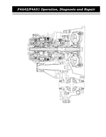
Original PrintingAugust, 2005INTRODUCTIONMITSUBISHI F4A41, F4A42, F4A51This is a four speed, Front Wheel Drive transaxle, with fully electronic controls for the upshifts and downshifts,with 4th gear being overdrive. The individual gear ratios are achieved through two planetary gear setsconnected one behind the other. The components of the planetary gear sets are driven or held by means of fivemultiple plate clutch packs, and some of the later models are equipped with a low sprag.To minimize fuel consumption, the torque converter clutch is applied by the TCM/PCM, depending on throttleposition and vehicle speed. This unit operates very much like the Chrysler 41TE transaxle.These units are currently found in several Mitsubishi models as shown in Figure 1, Dodge Stratus, someHyundai models and some Kia models.We wish to thank Mitsubishi Motor Company for the information and illustrationsthat have made this booklet possible. A special thanks also to Bob Nuttall forinformation and suggestions that has made this a very accurate booklet.No part of any ATSG publication may be reproduced, stored in any retrieval system or transmitted in any form orby any means, including but not limited to electronic, mechanical, photocopying, recording or otherwise,without written permission of Automatic Transmission Service Group. This includes all text illustrations,tables and charts.The information and part numbers contained in this booklet havebeen carefully compiled from industry sources known for theirreliability, but ATSG does not guarantee its accuracy.Copyright ATSG 2005DALE ENGLANDJIM DIALFIELD SERVICE CONSULTANTTECHNICAL CONSULTANTWAYNE COLONNAED KRUSETECHNICAL SUPERVISORTECHNICAL CONSULTANTPETER LUBANGREGORY LIPNICKTECHNICAL CONSULTANTTECHNICAL CONSULTANTJON GLATSTEINDAVID CHALKERTECHNICAL CONSULTANTTECHNICAL CONSULTANTJERRY GOTTROLAND ALVAREZTECHNICAL CONSULTANTTECHNICAL CONSULTANTGERALD CAMPBELLMIKE SOUZATECHNICAL CONSULTANTTECHNICAL CONSULTANTAUTOMATIC TRANSMISSION SERVICE GROUP9200 S. DADELAND BLVD. SUITE 720MIAMI, FLORIDA 33156(305) 670-41611
Technical Service InformationIDENTIFICATION CODE STAMPING LOCATIONUS AT IM K E N NP 889 9 6700P9B1K2E5F4A51F 4 A 51 K 2 E 5 B 1Manufacturing PlantDrive AxleK Kyoto WorksF Front Wheel DriveR Rear Wheel DriveNOTE: The "K" is not always stampedinto all transmission codes.Forward Speeds4 Four Speeds5 Five SpeedsTransmission TypeA AutomaticM ManualVEHICLE AND TRANSMISSION APPLICATION CHARTYEAR MODELENGINETRANSMISSION SPRAG1997 Diamante 3.5L SOHCF4A51-2-D5ANo1998-01 Diamante 3.5L SOHCF4A51-2-D5BYesTrans Capacity41 Light Duty42 Standard Duty51 Heavy Duty2000-0120002001EclipseEclipseEclipse2.4L SOHC3.0L SOHC3.0L -0119992000GalantGalantGalant2.4L SOHC3.0L SOHC3.0L -991997-9820001999-01MirageMirageMirageMirage1.5L SOHC1.8L SOHC1.5L SOHC1.8L NoYesYesCopyright 2005 ATSGFigure 1AUTOMATIC TRANSMISSION SERVICE GROUP3
Technical Service InformationGEAR RATIO IDENTIFICATIONUS AT IM K E N NP 889 9 6700P9B1A51K2E5F4F 4 A 51 K 2 E 5 B 1MANUFACTURING USE ONLYWhen the "K" is stamped into the code,this digit will be dropped off.DESIGN LEVEL1 1st Design2 2nd DesignSPRAG I.D.A No SpragB Has Low SpragNote: Refer to Page 117 for ImportantSprag Information.FINAL DRIVE RATIO *F4A41/42A N/AB N/AC N/AD N/AE 3.770F 3.769J 4.041L 4.212M 4.042N 4.406R 4.625T N/AU 4.407W 4.626F4A51A 3.269B 3.274C 3.491D 3.497E N/AF N/AJ N/AL 4.011M 4.018N N/AR 4.520T 4.316U 4.324W N/ASPEEDO GEAR RATIO **4 & M 27/365 & N 28/366 & P 29/367 & Q 30/368 & R 31/369 & S 32/36Note: Drive gear is 36 tooth.* The final drive ratios include the primary transfer gear reductionratio of 1.196 for the F4A41-42, and 1.119 for the F4A51.** The letter "Z" in the speedo gear position tells us that it is anelectronic calculation done by the computer.Copyright 2005 ATSGFigure 24AUTOMATIC TRANSMISSION SERVICE GROUP
Technical Service InformationMITSUBISHI F4A41, F4A42, F4A51 COMPONENT AND SOLENOID APPLICATION riveClutchOverdriveClutchLow Sprag(Some Models Only)FLUID REQUIREMENTSMitsubishi Diamond SP IIIGearRangeReverseClutchF4A41-42 Gear Ratios1st 2.8422nd 1.5293rd 1.0004th 0.712Rev 2.480F4A51 Gear Ratios1st 2.8422nd 1.4953rd 1.0004th 0.731Rev 2.720INTERNAL COMPONENT AND SOLENOID APPLICATION CHARTUnderdrive2nd Overdrive Low/Rev Low U.D. 2nd O.D. L/R TCCClutchClutch ClutchClutch Sprag Sol Sol Sol Sol SolParkONON ON ONReverseONONON ON ONNeutralON ON ONDr-1stONON* HOLD OFF ON ONDr-2ndONONOFF OFF ONDr-3rdONONOFF ON OFFDr-4thONONON OFF OFFM-3rdONONOFF ON OFFM-2ndONONOFF OFF ONM-1stONONOFF ON ON* Low/Reverse clutch is applied below 6 mph on units equipped with low sprag.** TCC dependant on throttle position, temperature and vehicle speed.Solenoid ON EnergizedSolenoid OFF De-EnergizedFailsafe: Two failsafe strategies are available, 2nd gear and 3rd gear.Should all solenoids be turned Off (i.e. electrical failure), 3rd gear will be the result.2nd gear failsafe can be commanded by the TCM, energizing the appropriate solenoids.OFFOFFONOFFONONON ON**ONONOFFCopyright 2005 ATSGFigure 3AUTOMATIC TRANSMISSION SERVICE GROUP5
Technical Service InformationCASE CONNECTOR TERMINAL IDENTIFICATION AND INTERNAL COMPONENT RESISTANCE CHART"Mitsubishi and Stratus Only"1096 5 48773 2 11 2 3View Looking Into TransaxleCase ConnectorCOMPONENTUnderdrive Solenoid2nd SolenoidOverdrive SolenoidLow/Rev SolenoidTCC SolenoidTFT Sensor8104 5 6View Looking Into TransaxleHarness ConnectorINTERNAL COMPONENT RESISTANCE CHARTTERMINALSRESISTANCETerminals 9 and 3Approximately 3.6 Ohms @ 72 FTerminals 9 and 4Approximately 3.6 Ohms @ 72 FTerminals 9 and 5Approximately 3.6 Ohms @ 72 FTerminals 10 and 6Approximately 3.6 Ohms @ 72 FTerminals 10 and 7Approximately 3.6 Ohms @ 72 FTerminals 1 and 2Approximately 9.05 k. Ohms @ 72 FTERMINALNUMBERINTERNALWIRE edYellowCIRCUITDESCRIPTION5 Volt Power to TFT SensorGround to TFT SensorGround to Underdrive SolenoidGround to 2nd Clutch SolenoidGround to Overdrive SolenoidGround to Low/Reverse SolenoidGround to TCC SolenoidNot UsedPower to Underdrive, 2nd, and Overdrive SolenoidsPower to TCC and Low/Reverse SolenoidsNOTE: Wire colors may vary.Figure 469AUTOMATIC TRANSMISSION SERVICE GROUPCopyright 2005 ATSG
Technical Service InformationWIRE SCHEMATIC GALANT AND STRATUS "ONLY"IGN FUSENO. 510A"Mitsubishi and Stratus Only"BATT FUSENO. 1320ATRANSMISSIONCONTROL RELAY1Red/White3To Park/NeutPosition SwitchSee Page erdriveSolenoidGreen2nd Blue8977{TCC torTFTSensorBlackTRANSAXLETCMBlackNOTE: Wire colors may vary.Copyright 2005 ATSGFigure 5AUTOMATIC TRANSMISSION SERVICE GROUP7
Technical Service InformationTCM CONNECTOR AND TERMINAL IDENTIFICATION"MITSUBISHI AND STRATUS" ONLYConnector C-115414758Connector C-11942 4344 45 4648 49 50 51 52 53 54 55 56 575960 61 62 6364 65 66Connector C-12371 72 73 7475 7678 79 80 81 82 83 84 85 86 87 8890 9192 93 9495 9697778998105106108 109 110 111 112 113 114 115 116 117 118101 102103 104119120121 122 123129130124 125126 127 128107Copyright 2005 ATSGFigure 6PARK/NEUT SWITCH CONNECTOR AND TERMINAL IDENTIFICATIONPower FromFuse BlockSee Page 7."Mitsubishi and Stratus Only"IGN FUSENO. 510A1 2 3 4 5 67Black/OrangeTo StartingSystem108910View Looking Into TransaxlePRNDL Switch Connector8Park/NeutralPosition utDInputNInputRInputPInputTCMBack-upLampsTCMNOTE: Wire colors may vary.Figure 78Red/BlueWhiteConnector C-123 110GreenYellow/BlueTo StartingSystemAUTOMATIC TRANSMISSION SERVICE GROUPCopyright 2005 ATSG
Technical Service InformationINPUT SPEED SENSOR CIRCUIT OPERATIONMITSUBISHI AND STRATUS ONLYWhen the key is turned on, you should see batteryvoltage at input speed sensor terminal 3. A coil builtinto the input shaft speed sensor generates a 0 - 5 voltpulse signal at both ends of this coil when the inputshaft rotates. The pulse signal frequency increaseswith a rise in input shaft speed. Both ends of the coilare connected to the TCM (terminals 57 and 103) viathe input shaft speed sensor connector (terminals 1and 2), as shown in Figure 5. The TCM detects theinput shaft speed by the signal input to terminal 103.The input shaft speed sensor generates the pulsesignal as the teeth on the underdrive clutch housingpass the magnetic tip of the rINPUT SPEED SENSORMITSUBISHI AND STRATUS ONLY3Copyright 2005 ATSGFigure 8OUTPUT SPEED SENSOR CIRCUIT OPERATIONMITSUBISHI AND STRATUS ONLYWhen the key is turned on, you should see batteryvoltage at output speed sensor terminal 3. A coil builtinto the output speed sensor generates a 0 - 5 voltpulse signal at both ends of this coil when the outputshaft rotates. The pulse signal frequency increaseswith a rise in output shaft speed. Both ends of the coilare connected to the TCM (terminals 57 and 104) viathe output shaft speed sensor connector (terminals 1and 2), as shown in Figure 5. The TCM detects theoutput shaft speed by the signal input to terminal 104.The output shaft speed sensor generates the pulsesignal as the teeth of the transfer drive gear pass themagnetic tip of the sensor.OUTPUT SPEED SENSORMITSUBISHI AND STRATUS ONLY3211Black2Green/YellowBlack/Orange3CONDITIONS TO SET DTCIf no output pulse is detected from the input shaftspeed sensor for one second or more, while driving in3rd or 4th gear at a speed of 30 km/h (19 mph) ormore, there is an open or short in the input shaft speedsensor circuit, and a DTC is set. When a DTC isoutput four times, the transaxle is locked into 2nd as afailsafe measure.GroundSignalPowerCONDITIONS TO SET DTCIf the output from the output speed sensor iscontinuously 50% lower than vehicle speed for onesecond or more, while driving in 3rd or 4th gear at aspeed of 30 km/h (19 mph) or more, there is an open orshort in the output speed sensor circuit, and a DTC isset. When a DTC is output four times, the transaxle islocked into 2nd as a failsafe measure.Copyright 2005 ATSGFigure 9AUTOMATIC TRANSMISSION SERVICE GROUP9
Technical Service InformationCASE CONNECTOR TERMINAL IDENTIFICATION AND INTERNAL COMPONENT RESISTANCE CHART"Hyundai Only"1096 5 48773 2 11 2 3View Looking Into TransaxleCase ConnectorCOMPONENTUnderdrive Solenoid2nd SolenoidOverdrive SolenoidLow/Rev SolenoidTCC SolenoidTFT Sensor8104 5 6View Looking Into TransaxleHarness ConnectorINTERNAL COMPONENT RESISTANCE CHARTTERMINALSRESISTANCETerminals 10 and 3Approximately 3.6 Ohms @ 72 FTerminals 10 and 4Approximately 3.6 Ohms @ 72 FTerminals 10 and 5Approximately 3.6 Ohms @ 72 FTerminals 9 and 6Approximately 3.6 Ohms @ 72 FTerminals 9 and 7Approximately 3.6 Ohms @ 72 FTerminals 1 and 2Approximately 9.05 k. Ohms @ 72 FTERMINALNUMBERINTERNALWIRE edYellowCIRCUITDESCRIPTION5 Volt Power to TFT SensorGround to TFT SensorGround to Underdrive SolenoidGround to 2nd Clutch SolenoidGround to Overdrive SolenoidGround to Low/Reverse SolenoidGround to TCC SolenoidNot UsedPower to TCC and Low/Reverse SolenoidsPower to Underdrive, 2nd, and Overdrive SolenoidsNOTE: Wire colors may vary.Figure 10109AUTOMATIC TRANSMISSION SERVICE GROUPCopyright 2005 ATSG
Technical Service InformationWIRE SCHEMATIC "HYUNDAI" ONLYPASSENGER COMPARTMENTFUSE BLOCKENGINECOMPARTMENTFUSE BLOCKPower ToP/N SwitchSee Page 12BATT FUSENO. BrownC93-3Conn.23Lt ange/Black15PurpleUnderdriveSolenoidGreen2nd 2Blue14TCC eenRedOSSSensorBrown2"Hyundai White31013 14 11 12PinkWhite2JOINT CONNECTORPower ToP/N SwitchSee Page 12241RedPinkTRANSMISSIONCONTROL RELAYBlackIGN FUSENO. 2510AGreenIGN FUSENO. ownNOTE: Wire colors may vary.Copyright 2005 ATSGFigure 11AUTOMATIC TRANSMISSION SERVICE GROUP11
Technical Service InformationTCM CONNECTOR AND TERMINAL IDENTIFICATION"HYUNDAI" ONLYConnector C93-311 10 98765Connector C93-24321822 21 20 19 18 17 16 15 14 13 12765432Connector C93-1113 12 11 10 916 15 14 13 12 11 10 98765432126 25 24 23 22 21 20 19 18 17 16 15 14Copyright 2005 ATSGFigure 12PARK/NEUT SWITCH CONNECTOR AND TERMINAL IDENTIFICATION"Hyundai Only"PASSENGER COMPARTMENTFUSE BLOCKIGN FUSENO. 2510AIGN FUSENO. 510A7108910View Looking Into TransaxlePRNDL Switch ConnectorPinkPurplePinkPurple1 2 3 4 5 68Park/NeutralPosition SwitchPLPRN6251473Lt GreenBlueLt GreenLt lowLTo StartingSystemConnector tPInputTCMTCMNOTE: Wire colors may vary.Figure 1312Back-upLampsAUTOMATIC TRANSMISSION SERVICE GROUPCopyright 2005 ATSG
Technical Service InformationGroundSignalPower"HYUNDAI" INPUT SENSOR CIRCUIT OPERATIONWhen the key is turned on, you should see batteryvoltage at input speed sensor terminal 3. A coil builtinto the input shaft speed sensor generates a 0 - 5 voltpulse signal at both ends of this coil when the inputshaft rotates. The pulse signal frequency increaseswith a rise in input shaft speed. Both ends of the coilare connected to the TCM (terminals 1 and 13) via theinput shaft speed sensor connector (terminals 1 and2), as shown in Figure 11. The TCM detects the inputshaft speed by the signal input to terminal 1. Theinput shaft speed sensor generates the pulse signal asthe teeth on the underdrive clutch housing pass themagnetic tip of the sensor.112Pink2White3BrownINPUT SPEED SENSOR"HYUNDAI" ONLY3Copyright 2005 ATSGCONDITIONS TO SET DTCIf no output pulse is detected from the input shaftspeed sensor for one second or more, while driving in3rd or 4th gear at a speed of 30 km/h (19 mph) ormore, there is an open or short in the input shaft speedsensor circuit, and a DTC is set. When a DTC isoutput four times, the transaxle is locked into 2nd as afailsafe measure.Figure 14"HYUNDAI" OUTPUT SENSOR CIRCUIT OPERATIONWhen the key is turned on, you should see batteryvoltage at output speed sensor terminal 3. A coil builtinto the output speed sensor generates a 0 - 5 voltpulse signal at both ends of this coil when the outputshaft rotates. The pulse signal frequency increaseswith a rise in output shaft speed. Both ends of the coilare connected to the TCM (terminals 2 and 13) via theoutput shaft speed sensor connector (terminals 1 and2), as shown in Figure 11. The TCM detects theoutput shaft speed by the signal input to terminal 2.The output shaft speed sensor generates the pulsesignal as the teeth of the transfer drive gear pass themagnetic tip of the sensor.OUTPUT SPEED SENSOR"HYUNDAI" S TO SET DTCIf the output from the output speed sensor iscontinuously 50% lower than vehicle speed for onesecond or more, while driving in 3rd or 4th gear at aspeed of 30 km/h (19 mph) or more, there is an open orshort in the output speed sensor circuit, and a DTC isset. When a DTC is output four times, the transaxle islocked into 2nd as a failsafe measure.Copyright 2005 ATSGFigure 15AUTOMATIC TRANSMISSION SERVICE GROUP13
Technical Service InformationFUSE BLOCK AND TCM LOCATIONS"MITSUBISHI" AND "DODGE" 5678912 13 141516PASSENGERCOMPARTMENTFUSE BLOCKTCMLOCATIONFUSE BLOCKLOCATIONCopyright 2005 ATSGFigure 1614AUTOMATIC TRANSMISSION SERVICE GROUP
Technical Service InformationFUSE BLOCK AND TCM LOCATIONS"HYUNDAI" GERCOMPARTMENTFUSE BLOCKPASSENGERCOMPARTMENTFUSE BLOCKLOCATIONTCMLOCATIONCopyright 2005 ATSGFigure 17AUTOMATIC TRANSMISSION SERVICE GROUP15
Technical Service Information"STRATUS" DIAGNOSTIC TROUBLE CODE P1400P1500P1751DescriptionTransaxle Range Sensor, Circuit MalfunctionTransaxle Fluid Temperature Sensor, Short CircuitTransaxle Fluid Temperature Sensor, Open CircuitInput Speed Sensor, Open Circuit/Short CircuitOutput Speed Sensor, Open Circuit/Short Circuit1st Gear Ratio Error2nd Gear Ratio Error3rd Gear Ratio Error4th Gear Ratio ErrorReverse Gear Ratio ErrorTorque Converter Clutch, Circuit Performance or Stuck OffTorque Converter Clutch, Circuit Performance or Stuck OnTorque Converter Clutch Solenoid, Open Circuit/Short CircuitLow/Reverse Solenoid, Open Circuit/Short CircuitUnderdrive Solenoid, Open Circuit/Short CircuitSecond Clutch Solenoid, Open Circuit/Short CircuitOverdrive Solenoid, Open Circuit/Short CircuitManifold Differential Pressure Sensor, Circuit MalfunctionGenerator FR Terminal, Circuit MalfunctionTransaxle Control Relay, Open Circuit/Short To GroundCODE RETRIEVAL REQUIRES SCANNEROBD-II Connector located on drivers side under dash.1 2 3 4 5 6 7 89 10 11 12 13 14 15 16Copyright 2005 ATSGFigure 1816AUTOMATIC TRANSMISSION SERVICE GROUP
Technical Service Information"HYUNDAI" DIAGNOSTIC TROUBLE CODE DescriptionStop Lamp Switch, Short Circuit/Open CircuitTransaxle Range Switch, Open CircuitTransaxle Range Switch, Short CircuitTransaxle Fluid Temperature Sensor, Short CircuitTransaxle Fluid Temperature Sensor, Open CircuitInput Speed Sensor, Open Circuit/Short CircuitOutput Speed Sensor, Open Circuit/Short CircuitCrank Position Sensor, Open Circuit1st Gear Ratio Error2nd Gear Ratio Error3rd Gear Ratio Error4th Gear Ratio ErrorReverse Gear Ratio ErrorTorque Converter Clutch, Defective SystemTorque Converter Clutch Solenoid, Open Circuit/Short CircuitLow/Reverse Solenoid, Open Circuit/Short CircuitUnderdrive Solenoid, Open Circuit/Short CircuitSecond Clutch Solenoid, Open Circuit/Short CircuitOverdrive Solenoid, Open Circuit/Short CircuitCAN-BUS OFF, TCM Failure Open/ShortCAN-TIME OUT ECU, ECM Failure Open/ShortThrottle Position Sensor, MisadjustedThrottle Position Sensor, Open CircuitThrottle Position Sensor, Short CircuitTransaxle Control Relay, Open Circuit/Short To GroundSerial Comunication Error, Connector, ECM, TCMCAN CONTROLLER CIRCUIT, TCM Failure Internal MalfunctionCODE RETRIEVAL REQUIRES SCANNEROBD-II Connector located on drivers side under dash.1 2 3 4 5 6 7 89 10 11 12 13 14 15 16Copyright 2005 ATSGFigure 19AUTOMATIC TRANSMISSION SERVICE GROUP17
Technical Service Information"KIA" DIAGNOSTIC TROUBLE CODE P0760P0765P1630P1631P1723P1764DescriptionVehicle Speed Sensor, Open/ShortStop Lamp Switch, Short Circuit/Open CircuitTransaxle Range Switch, Open CircuitTransaxle Range Switch, Short CircuitTransaxle Fluid Temperature Sensor, Short CircuitTransaxle Fluid Temperature Sensor, Open CircuitInput Speed Sensor, Open Circuit/Short CircuitOutput Speed Sensor, Open Circuit/Short Circuit1st Gear Ratio Error2nd Gear Ratio Error3rd Gear Ratio Error4th Gear Ratio ErrorReverse Gear Ratio ErrorTorque Converter Clutch, Stuck OnTorque Converter Clutch Solenoid, Open Circuit/Short CircuitLow/Reverse Solenoid, Open Circuit/Short CircuitUnderdrive Solenoid, Open Circuit/Short CircuitSecond Clutch Solenoid, Open Circuit/Short CircuitOverdrive Solenoid, Open Circuit/Short CircuitCAN-BUS OFF, TCM Failure Open/ShortCAN-TIME OUT ECU, ECM Failure Open/ShortTransaxle Control Relay, Open Circuit/Short To GroundCAN CONTROLLER CIRCUIT, TCM Failure Internal MalfunctionCODE RETRIEVAL REQUIRES SCANNEROBD-II Connector located on drivers side under dash.1 2 3 4 5 6 7 89 10 11 12 13 14 15 16Copyright 2005 ATSGFigure 2018AUTOMATIC TRANSMISSION SERVICE GROUP
Technical Service Information"MITSUBISHI" DIAGNOSTIC TROUBLE CODE 34446515253545671DescriptionThrottle Position Sensor, Short CircuitThrottle Position Sensor, Open CircuitThrottle Position Sensor, MisadjustedTransaxle Fluid Temperature Sensor, Open CircuitTransaxle Fluid Temperature Sensor, Short CircuitCrankshaft Position Sensor, Open CircuitInput Speed Sensor, Open Circuit/Short CircuitOutput Speed Sensor, Open Circuit/Short CircuitTransaxle Range Sensor, Open CircuitTransaxle Range Sensor, Short CircuitLow/Reverse Solenoid, Open Circuit/Short CircuitUnderdrive Solenoid, Open Circuit/Short CircuitSecond Clutch Solenoid, Open Circuit/Short CircuitOverdrive Solenoid, Open Circuit/Short CircuitTorque Converter Clutch Solenoid, Open Circuit/Short Circuit1st Gear Ratio Error2nd Gear Ratio Error3rd Gear Ratio Error4th Gear Ratio ErrorReverse Gear Ratio ErrorComunication Error With The Engine Control SystemTorque Converter Clutch, Circuit PerformanceTorque Converter Clutch, Circuit Performance or Stuck OnTransaxle Control Relay, Open Circuit/Short To GroundN Range Light System, Short to GroundMalfunction of Transaxle Control SystemSCANNER FOR CODE RETRIEVAL, OR "N" RANGEINDICATOR LIGHT ON INSTRUMENT CLUSTER"N" Range Indicator Light Method:OBD-II Connector located ondrivers side under dash.1 2 3 4 5 6 7 89 10 11 12 13 14 15 16Turn ignition off. Using jumper wire, ground terminal 1 of the DataLink Connector as shown at left. Turn ignition on. Read DTC's byobserving flash pattern of "N" range indicator light located oninstrument cluster. First series of flashes indicates first digit of DTC.Second series of flashes indicates second digit of DTC.Example: 2 flashes followed by a pause, and then 6 flashesindicates DTC 26.PRND2LCopyright 2005 ATSGFigure 21AUTOMATIC TRANSMISSION SERVICE GROUP19
Technical Service InformationTRANSAXLE DISASSEMBLYSAFETY PRECAUTIONSService information provided in this manual byATSG is intended for use by professional, qualifiedtechnicians. Attempting repairs or service withoutthe appropriate training, tools and equipment couldcause injury to you or others.The service procedures we recommend anddescribe in this manual are effective methods ofperforming service and repair on this unit. Some ofthe procedures require the use of special tools thatare designed for specific purposes.This manual contains CAUTIONS that you mustobserve carefully in order to reduce the risk of injuryto yourself or others. This manual also containsNOTES that must be carefully followed in order toavoid improper service that may damage the vehicle,tools and/or equipment.Continued on Page 21US AT IM K E N NP 889 9 6700P9EXTERNAL COMPONENTS1. The transaxle should be steam cleaned on theoutside, to remove any dirt or grease beforedisassembly begins.2. This transaxle can be disassembled very easilyon a work bench without the benefit of anyholding fixture for rotation.3. Remove the torque converter from transaxle,as shown in Figure 22.Caution: Use care when removing the torqueconverter, to avoid personal injury and/ordamage to converter, as it is heavy.E5B1F4A51K2A T FTORQUECONVERTERCopyright 2005 ATSGFigure 2220AUTOMATIC TRANSMISSION SERVICE GROUP
Technical Service InformationTRANSAXLE DISASSEMBLYEXTERNAL COMPONENTS (Cont'd)4. Remove the fluid level indicator from t
MITSUBISHI F4A41, F4A42, F4A51 AUTOMATIC TRANSMISSION SERVICE GROUP 9200 S. DADELAND BLVD. SUITE 720 MIAMI, FLORIDA 33156 (305) 670-4161 1 No part of any ATSG publication may be reproduced, stored in any retrieval system or transmitted in any form or