Transcription
OWNER'SMANUALPlease read thismanual BEFOREoperating yourbattery chargerSwitch Mode,Automatic, LeadAcid L
OWNER'S MANUAL: Battery Chargers IndexSECTION 1Safety Precautions . 3SECTION 2Layout. 4SECTION 3Description, Features & Cooling . 7SECTION 4Charging Stages & Protections . 8SECTION 5Installation & Charger Operation . 10SECTION 6Troubleshooting . 15SECTION 7Internal Fuse Rating & Specifications . 17SECTION 8Warranty. 18Disclaimer of LiabilityUNLESS SPECIFICALLY AGREED TO IN WRITING, SAMLEX AMERICA INC.:1. MAKES NO WARRANTY AS TO THE ACCURACY, SUFFICIENCY OR SUITABILITY OF ANY TECHNICAL OR OTHER INFORMATIONPROVIDED IN ITS MANUALS OR OTHER DOCUMENTATION.2. ASSUMES NO RESPONSIBILITY OR LIABILITY FOR LOSSES, DAMAGES, COSTS OR EXPENSES, WHETHER SPECIAL, DIRECT,INDIRECT, CONSEQUENTIAL OR INCIDENTAL, WHICH MIGHT ARISE OUT OF THE USE OF SUCH INFORMATION. THE USE OFANY SUCH INFORMATION WILL BE ENTIRELY AT THE USERS RISK.Samlex America reserves the right to revise this document and to periodically make changes to the contenthereof without obligation or organization of such revisions or changes.Copyright Notice/Notice of CopyrightCopyright 2016 by Samlex America Inc. All rights reserved. Permission to copy, distribute and/or modify thisdocument is prohibited without express written permission by Samlex America Inc.2 SAMLEX AMERICA INC.
SECTION 1 Safety PrecautionsHazardous conditions may result ifthe charger is not installed or operated correctly. Please read the followinginstructions to prevent personal injuryor damage to the charger: Install in a well ventilated, cool,dry place.Battery Related Do not block the ventilation openings/ openings for the cooling fan. Thereshould be at least 6 inches clearance allaround the unit To reduce the risk of battery explosion,follow these instructions and thosemarked on the battery Never smoke or allow an open sparkor flame in the vicinity of the battery orengine Charge only Lead Acid type of batteries(Flooded / Absorbed Glass Mat (AGM)/ Gel Cell). Do not charge other type ofbatteries like Nickel Cadmium(NiCad) Nickel-Metal Hydride (Ni-MH), Dry-Celletc. Other types of batteries might burstcausing personal injury Never charge a frozen battery Working in the vicinity of Lead Acid batteries is dangerous. Batteries generateexplosive gases during normal operation. Take necessary safety precautionswhen installing the charger near abattery or in a battery compartment(Follow safety instructions given by thebattery manufacturer) Never place the charger directly aboveor below the battery being charged;gases or fluids from the battery will corrode and damage the charger. Locatethe charger as far away from the battery as DC cables permit. Do not installin the same compartmentas batteries The charger must not be operated ina damp or wet environment. Whenmounting in a boat, make sure it is notsubjected to bilge water splash Installation and wiring must complywith the local and the nationalelectrical codes. It is recommended that installationand wiring may be done by acertified electrician Wrong installation on a boat may leadto corrosion of the boat. It is recommended that installation on the boatmust be carried out by a boat electrician Disconnect the AC input power to thecharger before connecting / disconnecting the batteries or other DC loads orwhen working on the charger Disconnect the AC input power beforechanging setting of the DIP Switch The chassis of the charger is connectedto the earth ground pin of the powercord plug. Ensure that the earth groundpin of AC receptacle feeding thecharger is connected to earth ground Do not use an adapter. If a groundingtype of receptacle is not available,do not use this charger until theproper outlet is installed by aqualified electrician. Do not operate the charger if the powercord is damagedCharger Related Do not operate the charger in a closedin area or restrict ventilation in any way.SAMLEX AMERICA INC. 3
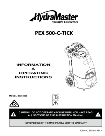
SECTION 2 Layout12Automatic 12V - 15A ModelSEC-1215ULBatteryCharger435678- LEGEND:1 - Ammeter2 - Red LED for ON status3 - AC input power cordFig. 2.1: Layout - SEC-1215UL4 SAMLEX AMERICA INC.4 - DIP Switches S1, S25 - Common NegativeOutput Terminal6, 7 & 8 - Isolated PositiveBank Terminals
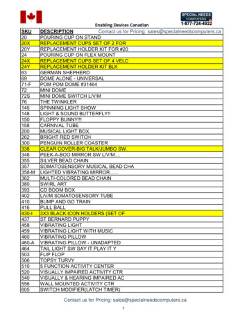
SECTION 2 Layout12Automatic 12V - 30A ModelSEC-1230ULBatteryCharger453678- LEGEND:1 - Ammeter2 - Red LED for ON status3 - AC input power cord4 - DIP Switches S1, S25 - Common NegativeOutput Terminal6, 7 & 8 - Isolated PositiveBank TerminalsFig. 2.2: Layout - SEC-1230ULSAMLEX AMERICA INC. 5
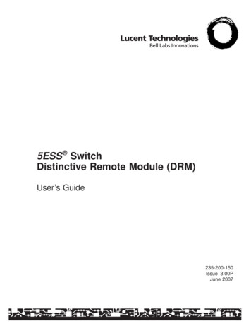
SECTION 2 Layout12Automatic 24V - 15A ModelSEC-2415ULBatteryCharger453LEGEND:1 - Ammeter2 - Red LED for ON status3 - AC input power cordFig. 2.3: Layout - SEC-2415UL6 SAMLEX AMERICA INC.678- 4 - DIP Switches S1, S25 - Common NegativeOutput Terminal6, 7 & 8 - Isolated PositiveBank Terminals
SECTION 3 Description, Features & CoolingDescriptionThese chargers are used to charge LeadAcid Batteries (Flooded, AGM or Gel Cell).SEC-1215UL (Maximum charging current15A) and SEC-1230UL (Maximum charging current 30A) are used to charge 12 Vbatteries. SEC-2415UL (Maximum chargingcurrent 15A) is used to charge 24 V batteries. These chargers can be poweredfrom AC power source of either 120 V, 60Hz (Pre-set) or 230 V, 50 Hz (By changingjumper position inside the unit - See page10 for instructions).Features State of the art switched mode technology is used for very high efficiency,lightweight and quiet operation. User selectable AC input voltage 120 V , 60 Hz (Pre-set) or 230 V , 50 Hz(By changing jumper position inside theunit (See page 10 for instructions). User selectable 2 or 3 stage chargingalgorithm ensures rapid and safe charging of all types of lead acid batteries- Flooded, AGM, Gel Cell or batterieswith external load. (Through externallyaccessible DIP Switch - see pages 11 forinstructions) Fully automatic "Connect and Forget"operation 3 banks of batteries can be chargedsimultaneously without use of anexternal battery isolator Protections against short circuit, overcurrent, reverse battery connection andover temperature (over temperature forSEC-1230UL and SEC-2415UL) Can be used as a power supply or asa DC UPS (Uninterruptible DC PowerSupply) when used with a battery (DIPSwitch set at "Battery with load")CoolingSEC-1215UL is cooled by convection anddoes not have any thermal overloadshut down.SEC-1230UL and SEC-2415UL are cooled byconvection and in addition, have a temperature controlled fan for forced air cooling. Two temperature sensors mounted onthe power transformer control the switching of the fan and over temperature shutdown. The fan will be switched on by thefirst temperature sensor when the powertransformer reaches 70 C.Hence, at lower loads, the fan may notcut in and will be off. This is normal.In case the fan fails or if the cooling is notadequate, the second temperature sensor will shut down the unit if the powertransformer reaches 100 C. The red LEDwill switch OFF. The unit will automaticallyrecover on removal of thermal overloadcondition. Monitoring through ON status LEDand Ammeter Temperature controlled cooling fan(SEC-1230UL, SEC-2415UL)SAMLEX AMERICA INC. 7
SECTION 4 Charging States & ProtectionsNOTES:1. VOLTAGE READINGS ON NO LOADThe output has one common Negative terminal and three Positive terminals for charging 3 banks of batteries. Each Positive terminal has an internal isolating diode in serieswhich has a forward voltage drop of 0.8 to 1.1 V. On no load (that is when no batteryor other DC load is connected to any of the 3 terminals) , the voltage reading willread 0.8 to 1.1 V higher than the specified float voltage. Note that the specified floatvoltage is at a load of 1 A. Also, the voltage on the terminals not connected to theload (for example, when one bank of battery is connected to one Positive terminal,the other 2 Positive terminals will remain disconnected) will read 0.8 to 1.1 Volt higherthan the voltage of the loaded terminal.2. VOLTAGE SPECIFICATIONSAll rated voltages are specified at battery temperature of 80 F.These chargers can be manually selectedto operate in 3 stage or 2 stage modes(Please see "Selecting the Type of Batteryand Charging Stages" at page 11) . Thecharging stages are described below:restored (Note: The percentage capacity restored till the point the batteryreaches the Boost or Absorption Voltage isinversely proportional to the value of thebulk charge current.)Stage 1 - Constant Current orBulk Charge StageStage 2 - Constant Voltage Boostor Absorption StageWhen the battery is low, it will try todraw larger charging current. The chargersenses the current draw and limits thisto the maximum permissible value (15Afor SEC-1215UL / SEC-2415UL and 30A forSEC-1230UL). Bulk charging takes place atthis constant current. In this condition ofconstant current, the voltage measuredat the charger or battery terminals will bethe battery's own voltage.As explained above, when the batteryvoltage approaches the point wherebattery "gassing" can begin, the chargerautomatically switches over to the "Boostor Absorption Stage". The charger appliesa constant voltage whose value dependsupon the type of battery selected (See DIPSwitch Settings). This controlled overcharge restores the balance 20% of thecapacity in a minimum amount of time. Asthe capacity is fully restored, the chargingcurrent starts reducing. When the currentreduces below the preset threshold, thecharger automatically switches to the"Float or Maintenance Stage".The constant current injected into thebattery starts restoring the battery capacity and it's voltage starts rising. Whenthis voltage approaches the thresholdof battery "gassing", termed "Boost orAbsorption Voltage", the charger automatically switches over to Stage 2 - "Boostor Absorption Stage". The value of thisvoltage depends upon the type of batterybeing charged (See DIP Switch Settings).By this time, approximately 80% of thebattery capacity will normally have been8 SAMLEX AMERICA INC.Stage 3 - Constant Voltage , Floator Maintenance Charging StageAs explained above, as the charging current drops below the preset threshold(1.5 to 2 amps for SEC-1215UL / SEC-2415ULand 2.5 A to 3 A for SEC-1230UL), it signalsthat the battery is 100% charged.
SECTION 4 Charging States & ProtectionsIn this "Float or Maintenance ChargingStage", the charger outputs a constantvoltage of 13.5 V for 12 V system and27 V for 24 V system. This helps in maintaining 100% capacity of the battery andalso compensates for self discharge. Thebattery can remain connected in this stageindefinitely without the risk of overcharging or excessive loss of electrolyte.CAUTION!3 stage charging is recommended forcharging stand-alone, unloaded batteries(there is no load connected to the batterywhen it is being charged).If a load is also connected simultaneously, apart of the charger's output current will bediverted to this load. Thus, the charger mayremain locked in the "Boost or AbsorptionMode" if the current drawn by the load ismore than the preset value of thresholdcurrent determining change over betweenthe Boost and Float Stages. This will lead toovercharging and loss of electrolyte.For charging a battery when a load is alsoconnected simultaneously, the "Boost orAbsorption Stage" is required to be disabled. Select "Battery with Load" using theDIP switch. See details under "Poweringother DC Loads" at page 14.THE CHARGER HAS THEFOLLOWING PROTECTIONS:Short Circuit Shut DownIn case of a short circuit on the output side,the charger will shut down. The Red LEDwill switch off. The charger will automatically recover once the short circuit condition is removed.Over load Current LimitingThe current drawn by the load is automatically limited to a maximum of 15 Afor SEC-1215UL / SEC-2415UL and 30 A forSEC-1230UL. If the load tries to draw ahigher current than these limits, the output voltage of the unit will start to drop.If a battery is connected, the outputvoltage will be clamped to the actualbattery voltage. The unit will automatically recover when the overload conditionis removed.Reverse Battery Connection Cut OffThe output is internally fused on the DCside. In case, the polarity of the batteryconnection is reversed, the fuse(s) willblow . The red LED will switch off. Thefuse(s) will be required to be replaced forthe unit to function again.Thermal Overload ShutdownSEC-1215UL is cooled by convection anddoes not have any thermal overloadshut down.SEC-1230UL and SEC-2415UL are cooled byconvection and in addition, have a temperature controlled fan for forced air cooling. Two temperature sensors mounted onthe power transformer control the switching of the fan and over temperature shutdown. The fan will be switched on by thefirst temperature sensor when the powertransformer reaches 70 C. Hence, at lowerloads, the fan may not cut in and will beoff. This is normal.In case the fan fails or if the cooling is notadequate, the second temperature sensor will shut down the unit if the powertransformer reaches 100 C. The red LEDwill switch off. The unit will automaticallyrecover on removal of thermal overloadcondition.CAUTION:Keep the charger in a well ventilated,cool and open area. Do not block the ventholes on the sides or the discharge openings of the cooling fan.SAMLEX AMERICA INC. 9
SECTION 5 Installation & Charger OperationINSTALLATIONLocation, Mounting & SafetyThe charger is required to be installed ina safe, well ventilated and dry location.Please see the details given under "Important Safety Instructions" on page 3.With the help of 4 screws, mount thecharger on a vertical bulkhead with theoutput terminal side facing down.Output connectorsA terminal block with tubular, screw downtype of terminals is used for output connection. The diameter of the tubular holesis as follows :SEC-1215UL0.14 inchesSEC-2415UL / SEC-1230UL0.19 inchesWires for Battery ConnectionTo avoid polarity errors and possibledamage, never use wires of only onecolor. Use red insulated wire(s) for Positive connection(s) and black for Negativeconnection(s)Recommended DC wire sizes are givenbelow. The length in feet is the length ofthe pair of the Positive and Negative DCwires from the charger to the battery /other DC load:Length ofthe pair ofthe Positive& NegativecablesSEC-1215ULSEC-2415ULSEC-1230UL0 to 6 ft.AWG #10AWG #86 to 10 ft.AWG #8AWG #610 to 20 ft.AWG #6AWG #410 SAMLEX AMERICA INC.Termination of Wire EndsWire ends for connection to the chargershould be terminated with pin type oflugs provided.CAUTION!For firm connection when using strandedcable, crimp / solder "pin" style terminalon the charger end of the DC wires usedfor connecting to the battery / other DCloads.CHARGER OPERATIONPreparing the Charger for Operation:Selecting AC input voltageThe charger is pre-set to operate frominput AC voltage of 120 VAC, 60 Hz.To operate the charger from AC inputvoltage of 230 VAC, 50 Hz, change theinternal setting as follows:1.Remove the 4 screws on the ammeterside of the top cover2.Gently slide the top cover out by 2 to3 inches. (CAUTION! The top coverwill be restrained from fully slidingout by the wires connecting the ammeter, LED and the fan)3.Locate the jumper wire with a quickfemale disconnect. In the pre-setcondition, it is connected to the malevertical pin marked "115 V". Pull thisfemale disconnect upwards to disconnect from the "115 V" position.Connect this to the male vertical pinmarked "230 V"4.Replace the fuse with the fuse recommended for 230 VAC operation (Seefuse rating at page 17)5.Replace the AC plug of the powercord with a suitable 3 pin grounded
SECTION 5 Installation & Charger Operationthe battery . A DIP Switch is provided ontop of the output terminals for selectingthe battery type and for disabling theBoost Stage when charging loaded batteries. The following selections can be madewith the help of the DIP Switch.plug to mate with the 230 VAC outlet. CAUTION: The new plug shouldhave 3 poles i.e. Line (L) , Neutral(N)and Earth ground. Color code for thepower cord conductors is:- Line (L) - Black- Neutral (N) - White- Earth ground - GreenCAUTION! Do not change the DIP Switchsetting when the charger is operating. Always change the DIP Switch setting whenthe charger is off , i.e. after disconnectingthe charger from the AC input power.Preparing The Charger ForOperation: Selecting The TypeOf Battery And Charging StagesThe Float Voltage and Boost Voltage (Alsocalled Absorption or Overcharge Voltage)of different types of Lead Acid Batteriesare different. Also, when a charger is usedto charge a battery and simultaneouslysupply a load , the Boost Stage is requiredto be disabled to prevent overcharging ofNOTE: The voltages are for a temperatureof 80 F.CAUTION! Please ensure that the positionNo. 4 of the DIP switch (S1-ON & S2-ON) isNEVER selected.DIP SWITCH SETTINGS: StagesS1S2OFF *ON *13.5 V *14.4 V *Flooded /AGM *3 Stages(Stages 1, 2, 3)ONOFF13.5 V14.0 VGel Cell3 Stages(Stages 1, 2, 3)OFFOFF13.5 VDisabledBattery withLoad2 Stages(Stages 1, 3)ONONCaution! Do NOT use this setting* Factory pre-set in this positionDIP SWITCH SETTINGS - FF *ON *27 V *28.8 V *Flooded /AGM *3 Stages(Stages 1, 2, 3)ONOFF27 V28.0 VGel Cell3 Stages(Stages 1, 2, 3)OFFOFF27 VDisabledBattery withload2 Stages(Stages 1, 3)ONONCaution! Do NOT use this setting* Factory pre-set in this positionSAMLEX AMERICA INC. 11
SECTION 5 Installation & Charger OperationConnecting The Batteries orOther DC LoadsThe output has a common Negative (-)terminal and 3 Positive terminals forcharging up to 3 independent banks ofbatteries. Each Positive connector has it'sown internal isolating diode which worksas a battery isolator. If more than one bankof batteries is connected, these will becharged at the same time as long as theAC power is available to the charger (themaximum charging current of 15 A ofSEC-1215UL/SEC-2415UL and 30 A ofSEC-1230UL will be shared among theconnected banks of the batteries depending upon their discharged states). In casethe AC power fails or if there is no outputfrom the charger, the isolating diodes willprevent charging / discharging among thebatteries connected to the banks.The above arrangement works as a batteryisolator and can divide the charging current into a maximum of 3 isolated branchesand allows current flow in each branch inone direction only. If more than one battery systems are being used independently,the system batteries will discharge todifferent levels. If system batteries are connected in parallel to charge from a singlecharger, a weak or a dead battery will drainthe charge from the strong battery. Suchsituation occurs in RVs, boats and othervehicles where 2 separate battery systemsare used – starter battery for starting andrunning the engine and the other auxiliary/ house battery system for running auxiliarydevices like inverters, refrigerators, carstereos etc. Here, the starter battery shouldbe connected to one bank and the auxiliary/ house battery to the second bank. Fig. 5.1shows this connection.In a single battery bank, two or morebatteries may be connected in parallel to12 SAMLEX AMERICA INC.increase their AH capacity. These will bedischarged and charged as a single batterybank. In this case, the paralleled bank ofmultiple batteries is to be considered asa single bank and connected to any oneof the 3 banks of the charger as shown inFig. 5.2 for bank of 4 batteries. For propercharging of all the batteries, please ensurethat the Positive wire “A” from the chargeris connected to the Positive terminal of thefirst battery (Battery 1) and the Negativewire “B” is connected to the Negativeterminal of the last battery (Battery 4). Thiswill ensure the following: Resistance of the interconnecting cableswill be balanced and the individual batteries will see the same series resistance All the individual batteries will becharged at the same charging currentand thus will be charged to the samestate of charge None of the batteries will see an overcharge conditionWhen connecting a single battery or othersingle DC load, it can be connected to thecommon Negative and any one of the 3Positive terminals as in Fig. 5.2.OPERATIONWhen the charger is switched on, thered LED lights up indicating that outputvoltage is available. When the batteriesare being charged or when the chargeris supplying other DC load, the currentfed by the charger will be indicated bythe ammeter.When the batteries are discharged, theywill draw charging current proportionalto their discharged condition (up to amaximum current rating of the charger)and this current draw will be shown by
SECTION 5 Installation & Charger Operation- - PositiveWire “A”StarterBatteryAuxilary /HouseBatteryNegativeWire “B”Battery 4Fig. 5.1:Connecting 2 separate battery systems to2 separate banks.the ammeter. When the batteries are fullycharged, they will draw very low current(may not be registered by the ammeter)to compensate for their self discharge.Charging a Battery Installed in a VehicleFollow these steps when the battery is installed in a vehicle. A spark near a batterymay cause battery explosion. For safetyand to reduce the risk of spark near thebattery:1. Position AC and DC cords to reduce riskof damage by hood, door or movingengine parts2. Stay clear of fan blades, belts, pulleysand other parts that can cause injury topersons3. Check the polarity of the battery posts.A Positive (Pos, P, ) battery post usuallyhas a larger diameter than a Negative(Neg, N, -) post4. Determine which post of the batteryis grounded (Connected to the chassisEngine Block). If the Negative post isgrounded to the Engine Block (As inBattery 3Battery 2Battery 1Fig. 5.2:Connecting bank of paralleled batteries tosingle bank.most vehicles), see sub paragraph 5. Ifthe Positive post is grounded, see subparagraph 6)5. For a Negative grounded vehicle, connect the Positive (red) DC wire from thecharger to the Positive of the batterypost. Connect the Negative (black) DCwire from the charger to a section ofheavy gauge metal part of the frame orengine block which is away from battery. Do not connect to carburetor, fuellines or sheet metal body parts.6. For a Positive grounded vehicle, connect the Negative (black) DC wire fromthe charger to the Negative of thebattery post. Connect the Positive (red)DC wire from the charger to a sectionof heavy gauge metal part of the frameor engine block which is away from battery. Do not connect to carburetor, fuellines or sheet metal body parts.7. Connect the charger AC power cord tothe AC outlet8. When disconnecting the charger, turnswitches to off, disconnect AC powerSAMLEX AMERICA INC. 13
SECTION 5 Installation & Charger Operationcord, remove connection from the vehicle chassis and then remove connectionfrom the battery terminalCharging a Battery outside the VehicleFollow these steps when the battery isoutside the vehicle. A spark near thebattery may cause battery explosion. Forsafety and to reduce risk of spark near thebattery, connect the charger as follows:1. Check the polarity of the battery posts.A Positive (Pos, P, ) battery post usuallyhas a larger diameter than a Negative(Neg, N, -) post2. Attach a piece of at least 3" of AWG #6insulated battery wire to the Negativebattery post3. Connect the Positive (red) DC wire fromthe charger to the Positive battery post4. Position yourself and the free end ofthe piece of wire attached to the Negative post as far away from the battery aspossible and then connect the Negative(black) DC wire from the charger to thefree end of the piece of wire attachedto the Negative battery post5. Do not face the battery when makingthe final connection6. Connect the charger AC power cordto the AC outlet7. When disconnecting the charger,always do so in reverse sequence ofconnecting procedure and break thefirst connection while standing as faraway from the battery as practical14 SAMLEX AMERICA INC.CHARGING MORE THAN ONEBANK OF BATTERIESCAUTION! When charging more than onebank of batteries at the same time using3 Stage Charging, ensure that the batteriesin the banks are in a similar dischargedcondition. If one bank is completelydischarged and another is almost fullycharged, the bank that is fully chargedwill be subjected to over charge conditionduring the time when the charger remainsin Boost Stage for charging the completelydischarged bank. If batteries are in dissimilar states of charge, select DIP Switchsetting for "Battery with Load."Powering Other DC LoadsThe charger can be used as a power supply or as a DC UPS . For both these applications, first set the DIP Switch to "Batterywith load". (See under " Selecting theType of Battery and Charging Stages" onpage 11).To use as a power supply, first switchoff the DC load. Connect the DC loadbetween the common Negative terminaland one of the three Positive terminals.Ensure that the maximum current drawnby the DC load is below the maximumcurrent rating of the charger. Switch onthe charger and then the DC load.In a DC UPS (Un-interruptible Power Supply) , the charger simultaneously powersthe DC load as well as the battery. As longas the AC power to the charger is available and the charger is working normally,the charger will supply the DC load as wellas charge/float the battery. In case the ACpower fails or if the charger stops work-
SECTION 5 Installation & Charger Operationing, the battery will automatically powerthe DC load. As soon as the AC power tothe charger is restored , the DC load willonce again be fed by the charger and atthe same time the battery will berecharged.To use as a DC UPS, first switch off theDC load and connect it to the battery.Now connect the battery as explainedabove under "Charging a Battery outsidethe Vehicle" on page 14. Switch on thecharger and then switch on the DC load.CAUTION! Please ensure that the sum ofthe current drawn by the DC load and thecurrent desired for charging the battery isless than the maximum current capacityof the charger.SECTION 6 TroubleshootingSYMPTOMS: CHARGER POWEREDAND CONNECTED TO THE BATTERYbattery may be loose or open. Check tightnessand continuity of the battery connection.The Red LED Is OFFThe DC side fuse may have blown due towrong polarity of battery connection.Ensure Positive of the battery is connectedto the Positive of the charger and theNegative of the battery is connected tothe Negative of the charger. Check thefuses inside the charger and replace, ifblown.The Battery Is Getting OverCharged or BoilsThe charger is also feeding other DCload(s) in parallel with the battery. TheDIP Switch is not selected for "Batterywith Load". Change DIP Switch setting to"Battery with Load" (see under "Poweringother DC loads" on page14.The battery may be shorted. In this condition, the unit is shut down by the shortcircuit protection circuit. Remove thebattery connection. If the red LED nowcomes on, the battery is shorted. If the redLED still does not come on, check if thereis AC power in the receptacle. If there ispower, check the AC side fuse inside theunit. If the fuse is not blown, call TechnicalSupport.The Red LED Is ON but the AmmeterShows No ReadingThe battery is fully charged. If the batteryis not fully charged, the connection to theSYMPTOMS: CHARGER POWERED& DISCONNECTED FROM BATTERYThe Red LED Is OFFCheck there is AC power in the receptacle.If there is power, check the AC side fuseinside the unit. If the fuse is not blown,check the DC side fuse. If the DC side fuseis not blown, the output may be shorted.In this condition, the charger is shut downby the short circuit protection circuit.Check that the output terminals are notshorted. If the terminals are not shorted,call Technical Support.SAMLEX AMERICA INC. 15
SECTION 6 TroubleshootingAC Side Fuse Blows As Soon AsPower Is Turned ONThe AC input is selected for 120 VAC butthe unit is plugged into 230 VAC. Alwayscheck that the charger is set for the correct AC mains voltage. If the AC inputvoltage is correct, the charger is defective.Call Technical Support.DC Side Fuse Blows As SoonAs The Battery Is ConnectedWrong polarity of the battery connection.Ensure Positive of the battery is connectedto the Positive of the charger and theNegative of the battery is connected tothe Negative of the charger.SYMPTOMS WHEN THE CHARGERIS POWERED AND IS BEING USEDAS A DC POWER SUPPLY/UPSThe Voltage Drops When Load Is Switched OnThe load is trying to draw current morethan the current limit value of the charger(the current limit value is the maximum16 SAMLEX AMERICA INC.specified charging Amps). Once the loadcurrent reaches the current limit value,the current limit circuit is activated andthe output voltage drops. Some loadslike motors, compressors, incandescentlamps, halogen lamps, heating elements,relays, coils, capacitors etc. draw very largeinrush/starting currents which may reachup to 10 times their normal operatingcurrents. Ensure that the starting / inrushcurrent or the maximum operating current of the load is lower than the currentlimit value of the charger.
SECTION 7 Internal Fuse Ratings & SpecificationsBoth the AC side and DC sides have fuses that are located inside the charger. Disconnectthe AC power when checking or changing the fuses. Open the charger as follows:1. Remove the 4 screws on the ammeter side of the top cover2. Gently slide the top cover out by about 2 to 3 inche
Absorption Voltage", the charger auto-matically switches over to Stage 2 - "Boost or Absorption Stage". The value of this voltage depends upon the type of battery being charged (See DIP Switch Settings). By this time, approximately 80% of the battery capacity will normally have been restored (Note: The percentage capac-