Transcription
Chapter 7MECHANICAL VENTILATION AND SMOKE CONTROL SYSTEMS7.1.AIR-CONDITIONING & MECHANICAL VENTILATION SYSTEMS7.1.1General(a)Where air-conditioning system is provided in lieu of mechanicalventilation system during emergency, all the requirementsspecified in this Code for the mechanical ventilation system shallapply to the air-conditioning system.(No illustration)The term “air conditioning” has been defined by the American Society of Heating,Refrigerating, and Air Conditioning Engineers as:“Air conditioning is the process of treating air so as to control simultaneously itstemperature, humidity, cleanliness and distribution to meet the requirements of theconditioned space”The use of air conditioning and mechanical ventilation systems will invariably, exceptfor self-contained units, involve some use of pipe works for refrigerant/watercirculation and ducts for air distribution and extraction.The use of ducts present the inherent possibility of spreading fire, heat, gases andsmoke throughout the building or the floors/areas served.Where air conditioning system is designed to operate during fire emergency, it is to beemphasized that the system shall comply with all the relevant requirements for themechanical ventilation system in this Code.(b)Construction of ductworkDucts for air-conditioning and mechanical ventilation systemsshall be constructed in compliance with the followingrequirements:(i)All air-conditioning or other ventilation ducts includingframing thereof, shall be constructed of steel, aluminium,glass-fibre batt or mineral-wool batt or other approvedmaterial.(ii)All air-conditioning or other ventilation ducts shall beadequately supported.(iii)Duct lining & coverings1
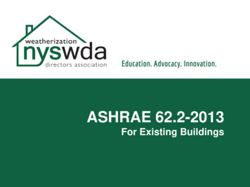
Duct covering and lining should be non-combustible.However, if it is necessary to use combustible material, itshall:-(iv)*when tested in accordance with methods specified inthis Code, have a surface flame spread rating of notlower than Class 1, but in areas of building where Class0 flame spreading rating is required for the ceilingconstruction under this Code, a Class 0 rating for thecovering and lining materials shall be required;*when involved in fire generate a minimum amount ofsmoke and toxic gases; and*be at least 1.0m away from a fire damper.Flexible joint and connectionMaterials and installation of all flexible joints andconnections shall be in accordance with SS CP 13 Codeof Practice for Mechanical Ventilation and Airconditioning in Buildings.Diagram 7.1.1(b)2
Minimum Class 1 for insulation material/barrier lining and adhesives. Where ceilingconstruction requires class 0, covering and lining insulation material shall also beclass 0. Where combustible material is used for the insulation of the duct, it shall bekept at least1000mm away from a fire damper in order to prevent prematureclosing of the damper arising from a fire from the combustible insulation material.For flexible joints and connections, which are combustible, there is a need to limitthe length of the joints and connection to max. 250mm and 400mm respectively.Please see clause 1.2.35 in Volume1 for illustration.7.1.1(c)Pipework insulationInsulation for pipework associated with the air-conditioningand mechanical ventilation systems shall comply with thefollowing requirements:(i)Insulation material for pipework together with vapourbarrier lining and adhesives shall when tested inaccordance with the methods specified in this Code,have a surface flame spread of not lower than Class 1but in areas of buildings where Class 0 flame spread isrequired for the ceiling construction under this Code, aClass 0 rating for the insulation material shall berequired.(ii)Plastic and foam rubber insulationNotwithstanding the requirements of sub-clause (c)(i),the use of plastic and foam rubber insulation materialsof a lower classification may be permissible if:*the material is the self-extinguishing type to thesatisfaction of the Relevant Authority;*the insulation material is covered by or encased in ametal sheath or hybrid plaster or othernon-combustible cladding materials acceptable tothe Relevant Authority.provided that any opening in the element of structure orother part of a building penetrated by the pipeworkshall be effectively fire-stopped by replacement of theinsulation material at the junction of penetration with fireresistant material having equal fire rating. Fire ratedproprietary pipework system may be used if it is tested inthe manner acceptable to the Relevant Authority.3
Diagram 7.1.1(c)-1Diagram 7.1.1(c)-24
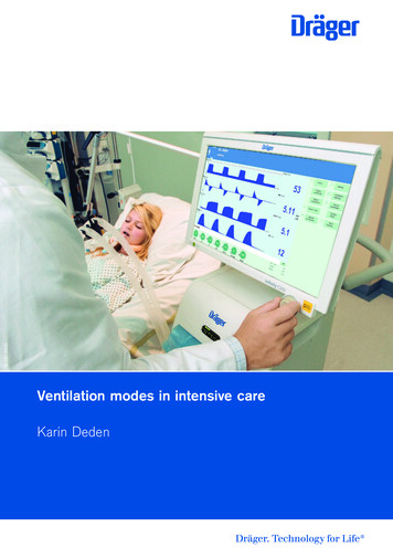
Minimum class 1 for insulation material/barrier lining and adhesives. Where ceilingconstruction requires class 0, insulation material shall also be class 0. However, theuse of 10mm to 15mm maximum diameter pipe works for split unit system wouldbe considered as acceptable.The use of fire collar shall be appropriate for the diameter of the PVC/UPVC pipeand shall be duly secured to the surface of the wall or floor with steel anchorbolts. See Table 3.9A of the fire code for the maximum nominal internal diameterof pipes.(d)Duct enclosureEnclosure of ducts shall comply with the requirements insub-clause 3.8.9(a).(No illustration)A protected shaft used for the enclosure of services shall comply with thefollowing:5
(a)The protecting structure for protected shaft containing kitchenexhaust duct and mechanical ventilation ducts serving areasspecified in Cl. 5.2.1(g)(i) to (iii) and (h) which pass through one ormore floor slabs shall be constructed masonry. Such shaft shall becompletely compartmented from the rest of the shaft spacecontaining other ducts or any other services installations.Note: CL.5.2.1(g) –(i)(ii)(iii)exit staircases and exit passagewaysmoke-stop lobby and fire fighting lobbyareas of refuge within the same buildingCl.5.2.1(h) –(i)emergency generatorengine driven fire pump(e)Ductwork through smoke-stop or fire fighting lobbiesVentilation ducts should not pass through smoke-stop or firefighting lobby.Where unavoidable, the part of theventilation duct within the lobby shall be enclosed inconstruction with fire resistance rating at least equal to thatof the elements of structure. Such construction shall be inmasonry. If other form of fire resisting construction is used, firedamper shall be fitted where the duct penetrates the lobbyenclosure.6
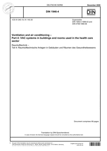
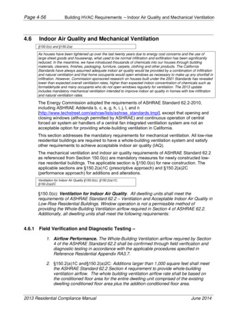
Ventilation ducts are routed from The AHU Roomsdirectly into the office spaceDiagram 7.1.1(e) - 1With proper pre-planning, ventilation ducts are routed directly from the AHU roomsto occupancy areas, thus avoiding the routing through the protected lobby.7
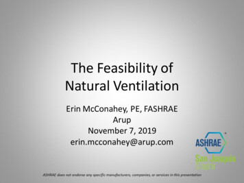
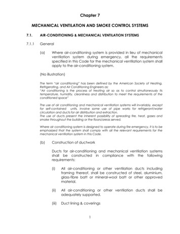
Ventilation ducts are routed along protected lobbyDiagram 7.1.1(e)-2Ventilation ducts are routed along the Smoke Stop Lobby to serve Office 2& 3. Routing the ventilation ducts through the fire lift or smoke stop lobbiesshould be avoided. “Unavoidable situations” where ventilation ducts wererouted through the fire lift or smoke stop lobbies referred to existing buildingwhere physical constraints existed making it difficult to route the ventilationduct through other spaces other than the lobby area.8
Diagram 7.1.1(e)-3In addition to providing fire rated enclosure to the duct within the lobby, firedamper is fitted where the duct penetrates the lobby enclosure. Should a firepenetrates the fire damper, it still be contained within the duct.The omission of fire damper to the duct where it penetrates the lobbyenclosure is acceptable if a masonry slab is constructed below the ductto act as compartment ceiling. The masonry slab over the lobbycompletes the compartmentation, thus making the lobby a safe area.9
(f)PlenumA concealed space between the ceiling and floor above it,ceiling and roof, or raised floor and structural floor of a buildingmay be used as a plenum provided that(i)(ii)The concealed space contains um-sheathedcable,copper-sheathedcable, rigid metal conduit, enclosed metal trunking,flexible metal conduit, liquid-tight flexible metalconduit in lengths not more than 2 m, or metal-cladcables;*electric equipment that is permitted within theconcealed spaces of such structures if the wiringmaterials, including fixtures, are suitable for theexpected ambient temperature to which they willbe subjected;*other ventilation ducts complying with sub-cl. (b);*communication cables for computers, television,telephone and inter-communication system;*fire protection installations;*pipes of non-combustiblenon-flammable liquids.The supports for the ceilingnon-combustible material.10materialconveyingmembraneareof
Diagram 7.1.1(f)-1Diagram 7.1.1(f)-2A fire occurring in the concealed space would be difficult to detect. Thesmoke and heat could quickly spread beyond the origin of fire in theconcealed space.To restrict the unseen spread of smoke and heat in concealed spaces,additional fire safety requirements are imposed under f(I) and (ii).11
(g)Separating wallsNo air conditioning or ventilation ducts shall penetrateseparating walls.Diagram 7.1.1(g)In terrace shophouses, the separating walls are also compartment walls, hence,there should be no sharing of air-con ducts.In Commercial Complexes where shops/offices are located, the separating wallthat separates one shop or office unit from another is not treated as compartmentwall, as such, the requirement that air-con duct should not penetrate theseparating wall should not apply.(h)Provision of Fire Dampers(i)Ventilation ducts which pass directly through acompartment wall or compartment floor shall complywith the following *where the ventilation duct does not form aprotected shaft or is not contained within aprotecting structure, the duct shall be fitted with afire damper where it passes through thecompartment wall or compartment floor;12
*where the ventilation duct forms a protected shaftor is contained within a protecting structure, theduct shall be fitted with fire dampers at the inlets tothe shaft and outlets from it.Diagram 7.1.1(h)(i)-1Exposed ventilation duct is not fire rated. Fire damper is provided where itpasses through the compartment floor or wall to prevent fire spread fromcompartment to compartment via the duct.Exposed ventilation duct located outdoor shall be weather proof type.Fire rating the duct is not required.13
Ventilation duct containedWithin protected shaftVentilation duct formsA protected shaftDiagram 7.1.1(h)(i)-2To prevent fire spread from compartment to compartment via the duct,fire damper shall be provided at the inlets to the exhaust air shaft andoutlets from supply air shaft.The dampers shall be properly secured to the protecting structure orprotected shaft to prevent any displacement.Fire dampers are provided to inlets of exhaust air shaftsand outlets of supply air shaft14
Diagram 7.1.1(h)(i)-3(ii)Provision of fire dampers not requiredConditions under which fire dampers are not required tobe fitted in openings of compartment walls and floorsshall be in accordance with SS CP 13 Code of Practicefor Mechanical Ventilation and Air-conditioning inBuildings.Clause 6.4.5.3 of SS CP 13 allows the omission of fire dampers atopenings in fire resisting walls when:(a) the opening has a horizontal supply branch duct passingthrough it and has a cross sectional area not greater than0.02m² and is located at a height not greater than 1.2m abovefloor level and at distance not less than 6m from other similarunprotected opening; and(b) the opening is located at the wall of a return-air shaft which isfire rated and maintained at a negative pressure at all timesand that air is discharged into the shaft through a sub duct ofnon-combustible material.15
Diagram 7.1.1(h)(ii)A subduct is an entry piece intended to prevent back flow (venturieffect) of air or products of combustion into non-fire affectedcompartments. It shall be manufactured from steel of 2mmminimum thickness or be otherwise constructed to have the samefire resistance rating as that required for the shaft.An acceptable alternative material is reinforced concrete integralwith the reinforced concrete shaft. If the above designs are to beadopted, QPs shall comply fully with the requirements listed underCL.6.4.5.3 of SS CP13 and full details shall be given on plan forapproval.16
(h)(iii)Fire dampers shall not be fitted in the followinglocations:*openings in walls of a smoke extract shaft or returnair shaft which also serves as a smoke extract shaft;*openings in walls of a protected shaft when theopenings have a kitchen exhaust duct passingthrough it; or*anywhere in an air pressurising system;*where explicitly prohibited in this Code.Diagram 7.1.1(h)(iii)Fire dampers shall not be fitted in any of the smoke extract shaft. The smokepurging system would not be able to function effectively as the fire damperswhen subjected to high temperature would close.Smoke purging system is not intended for escape purposes but for dilution ofsmoke. Hence, there is no need to fire rate the duct works.Fire dampers shall not be provided in the following locations:a) openings in walls of a protected shaft if such openings have a kitchenexhaust duct passing through them;b) anywhere in the supply duct work of air pressurising system to exitstaircase; andc) anywhere in the supply and exhaust ducts serving fire pump room,generator room, fire command centre and flammable store.17
(iv)Where a fire damper is required by this Code to beinstalled in the airconditioning and mechanical system,its type, details of installation, connection of accessories,inspection door, etc. shall be in accordance with SS CP13 Code of Practice for Mechanical Ventilation and Airconditioning in Buildings. Construction of the firedamper shall comply with requirements in SS 333Specifications of Fire Dampers.(No illustration)(i)Fire resisting floor-ceiling and roof-ceiling(i)The space above a suspended ceiling which forms partof a fire-rated floor ceiling or roof-ceiling constructionshall not contain ducting unless ducting wasincorporated in a prototype that qualified for therequired fire-resistance rating, in which case the ductingshall be identical to that incorporated in the testedprototype.Ducting above fire rated ceiling or roof ceiling constructionDiagram 7.1.1(i) - 118
Diagram 7.1.1(i) – 2Mechanical ventilation ducts are not permitted to be located in theconcealed space of fire rated floor ceiling or roof ceiling assembly, unlesssuch ducts are included in the prototype that was tested for the requiredfire resistance rating. The type of ducting within such ceiling or roof spacesas well as details of openings in such ceiling shall be identical to thatincorporated in the tested prototype.Diagram 7.1.1(ii)* Area of opening to be protected by fire damper shall not be greater or larger thanthat in the prototype test panel.* Total area of openings in the ceiling to each compartment shall not be greaterthan that of the prototype test panel.* The opening for fire damper may be relocated provided the proximity to structuralmember (a and b) eg. column, beams and structural walls is not less than that inthe prototype test panel.19
During a fire, the radiant heat from the fire damper would affect the performance ofthe structural members eg. I-beam in the ceiling space. Hence, the distancebetween any opening to any structural member shall not be less than that in theprototype test panel.7.1.1(i)(ii)Openings in the ceiling, including openings to enablethe ceiling to be used as a plenum, shall be protectedby fire dampers identical to those used in the testedprototype and such openings in the ceiling shall be soarranged that –*No opening is greater in area thancorresponding in the prototype test panel;that*The aggregate area of the openings per unit ceilingarea does not exceed that of the prototype testpanel; and*The proximity of any opening to any structuralmember is not less than that in the prototype testpanel.Diagram 7.1.1(ii)*Area of opening to be protected by fire damper shall not be greater or largerthan that in the prototype test panel.*Total area of openings in the ceiling to each compartment shall not be greaterthan that of the prototype test panel.*The opening for fire damper may be relocated provided the proximity (a and b)to structural member eg. column, beams and structural walls is not less than thatin the prototype test panel.20
During a fire, the radiant heat from the fire damper would affect the performance of thestructural members eg. I-beam in the ceiling space. Hence, the distance between anyopening to any structural member shall not be less than that in the prototype test panel.*(j)The opening (A & B) may be relocated within the ceilingarea provided the proximity to structural member, eg.column, beams and structural walls is not less than that inthe prototype test panel.Fire Rated Duct(i)Where proprietary fire rated materials are used toconstruct the fire rated duct, the fire rating of the firerated shall have the same period of fire resistance asthe wall or floor it penetrates.(ii)Proprietary fire rated duct shall be tested to BS 476 Pt 24or equivalent and its usage be approved by theRelevant Authority.(iii)Running of non-fire rated duct and/or other buildingservices above the proprietary fire rated duct should beavoided. When unavoidable due to physicalconstraints, the supports to such non-fire rated ductand/or other building services running above theproprietary fire rated duct shall be strengthened suchthat the tensile stress generated on the supports shallnot exceed 10N/mm² and the non-fire rated ductand/or building services shall also be adequatelyprotected to prevent collapse in a fire which willotherwise affect the stability of the proprietary fire ratedduct below.21
Diagram 7.1.1(i)(iii)(iv)Fans forming part of a fire rated duct shall also beenclosed in the same fire rated enclosure.(No illustration)7.1.2Air handling unit room(a)Air handling unit roomsRooms having no other usage than housing air handlingequipment or package units, and their associated electricalcontrols are not regarded as areas of high risk. However, insituations where the air handling equipment serves morethan one compartment, fire dampers shall be provided in airducts at penetration through the compartment walls andfloors to comply with the requirements in Cl.7.1.1(h).(b)Smoke detectorsSmoke detectors of approved type shall be incorporated inthe return air stream immediately adjacent to:22
(c)(i)air handling units serving more than one storey orcompartment; or(ii)a single unit in excess of 15000m³/h; or(iii)any AHU as may be required by the RelevantAuthority.The function of smoke detectors where required by this codeis to initiate action to shut down the AHU automaticallywhen the smoke density in the return-air has becomeunacceptable for recycling. Details of the requirements shallbe in accordance with SS CP 13 Code of Practice forMechanical Ventilation and Air-conditioning in Buildings.An AHU serving 2 fire compartmentsDiagram 7.1.2 - 123
Air duct penetrating a compartment wall being fitted with a fire damperDiagram 7.1.2-2To prevent the spread of smoke and flame from one fire compartment toanother served by a single AHU, smoke detector shall be incorporated in thereturn air stream adjacent to air handling unit. The smoke detector is toinitiate action to shut down the AHU automatically when smoke is drawn intoreturn air system. The fire damper located in the fire compartment wall orfloor where the air duct penetrated would only be activated by a fire in anyof the compartment. The closing of the fire damper would prevent thespread of fire and, to some extent, the spread of smoke from onecompartment to another.24
7.1.3Exits(a)Protected shaft of exits, smoke-stop lobbies, including itsconcealed space shall not be used for supply, exhaust orreturn air plenum of air handling systems.Diagram 7.1.3(a)The protection of these spaces as means of escape is important. They mustnot be used as air plenum by other systems.7.1.3(b)Mechanical ventilation system for each exit staircase andinternal exit passageway, if provided, shall be anindependent system of supply mode only exclusive to theparticular staircase, and it shall comply with the followingrequirements:(i)Supply air for the system shall be drawn directly fromthe external, with intake point not less than 5 m fromany exhaust discharge openings.(ii)For exit staircase serving more than 4 storeys, supplyair shall be conveyed via a vertical duct extendingthroughout the staircase height and discharging fromoutlets distributed at alternate floor.25
Diagram 7.1.3(b)(i)There is a need to separate supply air fan from the exhaust louvres by atleast 5m measured from the edge of the exhaust louvres housing. This is toprevent the possibility of smoke being drawn into the supply air shaft.For maintaining uniformity of air distribution in the staircase it would bedesirable to place the supply air outlet at every floor level, but should not bemore than alternate floors. The supply air system to the staircase shall be anindependent system as it is expected to operate during emergency toprovide smoke free environment to serve occupants evacuating in thestaircase.(iii)Where the supply air duct serving the exit staircase hasto penetrate the staircase enclosure, the portion of theduct where it traverses outside the staircase shall beenclosed in masonry construction of at least the samefire resistance as the element of structure and it shallnot be fitted with fire dampers.26
Diagram 7.1.3(b)(iii)The supply air duct is considered as part of the exit staircase, as such that part ofthe duct, which traverses outside, shall be protected with masonry. As exitstaircase is the means of escape, protecting it with masonry would ensure thedurability of the shaft during fire situation.As far as possible, the supply air duct should be located within the protectedshaft, unless it is unavoidable.7.1.4Mechanical ventilated smoke-stop lobby and fire fighting lobbyMechanical ventilation system for smoke-stop lobbies and firefighting lobbies shall be a system exclusive to these lobbies, and itshall comply with the following requirements:(a)The ventilation system shall be of supply mode only of notless than 10 air changes per hour.(b)Supply air shall be drawn directly from the external withintake point not less than 5m from any exhaust discharge oropenings for natural ventilation.27
(c)Any part of the supply duct running outside the smoke-stopor fire fighting lobby which it serves shall either be enclosedor constructed to give a fire resistance rating of at least 1 hr.The Relevant Authority may at its discretion require a higherfire resistance rating if the duct passes through an area ofhigh fire risk.(d)The mechanical ventilation system shall be automaticallyactivated by the building fire alarm system. In addition, aremote manual start-stop switch shall be made available tofiremen at the fire command centre, or at the fire indicatingboard where there is no fire command centre. Visualindication of the operation status of the mechanicalventilation system shall be provided.Diagram 7.1.4(c)28
The above diagram shows that the supply air duct to the smoke stop lobbies orfire fighting lobbies is provided with fire damper where it penetrates thecompartment wall of the lobby. This is to ensure that the floor to floorcompartmentation is maintained.The portion of the duct which traverse outside the protected shaft is enclosed infire rated construction e.g. fire rated boards.The main purposes of locating the manual start/stop switch with visual indicationat the fire command centre, or at the main fire indicating board (FIB) where thereis no fire command centre are:a) to allow fire fighting personnel to shut down the supply air system temporarilyin the event that smoke is being drawn into the lobby through the outdoor airintake; andb) to allow fire fighting personnel to activate the supply air system should the firealarm system fail to automatically activate the supply air system.7.1.5Engine driven fire pump and generator roomWhere mechanical ventilation is installed to provide air for theoperation of the following equipment, such system shall beindependent of each other and any other system serving other partsof the building:-engine driven fire pump;-emergency generator;(a)Supply air shall be drawn directly from the external and itsintake point shall not be less than 5 m from any exhaustdischarge openings. Exhaust discharge shall also be direct tothe external and shall not be less than 5 m from any air intakeopenings.29
Diagram 7.1.5(a)The 5m clearance between supply and exhaust units refers to the horizontaldistance. This is to prevent the recycling of exhaust air back into the building.(b)Where the corresponding ducts run outside the room theyshall either be enclosed in a structure or be constructed togive at least the same fire rating as the room which theyserve or that of the room through which they traverse,whichever is higher. The rating shall apply to fire exposurefrom both internal and external of the duct or structure.Where the duct risers are required to be enclosed in amasonry shaft, or dry wall complying with Cl. 3.8.9(a), theyshall be compartmented from the rest of the shaft spacecontaining other ducts or services installations.(c)No fire damper shall be fitted in either supply or exhaust ductrequired under this clause.30
Diagram 7.1.5(b) - 1The above diagram shows that the ducts that run outside the protected masonryshaft are enclosed in a structure or be constructed to give the necessary fireresistance rating.However, for the riser ducts, which pass through one or more floors, they arerequired to be enclosed in fire rated shaft as required under Cl.3.8.9. This is toensure that the riser ducts are properly protected.The provision of fire damper to the supply and exhaust ducts is not permitted asthe supply or exhaust system is required to function during emergency.Diagram 7.1.5(b) - 231
As the mechanical ventilation system to generator room and fire pump room isindependent of each other, the riser duct for each system shall be separatelyenclosed in a masonry shaft and compartmented from the rest of the shaft spacecontaining other ducts or service installations.(d)Duct serving areas other than rooms housing equipment statedin this clause shall not pass through such rooms.Diagram 7.1.5(d)Ducts serving other areas shall not pass through the fire pump room,generator room and fire command centre. The above diagram shows thatthe ventilation duct is diverted to avoid traversing the aforesaid rooms.7.1.6Fire command centreWhere mechanical ventilation is required for the fire commandcentre, such system shall be independent of each other and anyother system serving other parts of the building. It shall also complywith the following requirements:(a)Supply air shall be drawn directly from the external and itsintake point shall not be less than 5m from any exhaustdischarge openings. Exhaust discharge shall also be direct tothe external and shall not be less than 5m from any air intakeopenings.32
(b)Where the corresponding ducts run outside the fire commandcentre, they shall either be enclosed in a structure or beconstructed to give at least the same fire rating as the roomwhich they serve or that of the room through which theytraverse, whichever is higher. Where the duct risers are requiredto be enclosed in a masonry shaft, or dry wall complying withCl. 3.8.9(e) they shall be compartmented from the rest of theshaft space containing other ducts or services installations.(c)No fire damper shall be fitted in either supply or exhaust ductrequired under this Clause.(d)Duct serving areas other than the fire command centre shallnot pass through the room.For illustration of the above see Cl.7.1.5(a) to (d)7.1.7Kitchen(a)Mechanical exhaust system for the cooking area of a kitchenin a hotel, restaurant, coffee house or the like shall beindependent of those serving other parts of the building. It shallalso comply with the following requirements:(i)The hood and ducts for the exhaust shall have aclearance of 500mm from unprotected combustiblematerials;Diagram 7.1.7(a)(i)33
The hood and duct should be separated from other combustible materialsby a minimum horizontal clearance of 500mm to prevent ignition throughheat radiation.(ii)The exhaust shall be discharged directly to the externaland shall not be less than 5m from any air intakeopenings;(iii)The exhaust duct where it runs outside the kitchen shalleither be enclosed in a structure or be constructed togive at least the same fire rating as the kitchen or that ofthe room it traverses, whichever is higher. The rating shallapply to fire exposure from both internal and external ofthe duct or structure. Where the duct riser is required tobe enclosed in a protected shaft constructed ofmasonry or dry wall complying with Cl. 3.8.9(a), it shall becompartmented from the rest of the shaft spacecontaining other ducts or services installations; and(iv)No fire damper shall be fitted in kitchen exhaust ducts.Diagram 7.1.7(a) – 134
Diagram 7.1.7(a)-2Horizontal run of the exhaust duct outside the kitchen shall be fire rated withminimum 1-hour fire resistance rating. The 1-hour fire resistance shall be applicable tothe inside and outside of the duct. The capacity of exhaust fan shall be inaccordance with CP 13.Diagram 7.1.7(a)-3The protecting structure for protected shaft containing kitchen exhaust duct thatpass through more than one or more floors shall be of masonry construction.To eliminate the risk of fire spreading from one compartment to another throughburning grease within the duct system, a separate exhaust system is required foreach hood located in separate compartments.35
Fire dampers are not permitted within the duct system. The effectiveness of firedampers is questionable as accumulation of grease would jam the operation of
Refrigerating, and Air Conditioning Engineers as: "Air conditioning is the process of treating air so as to control simultaneously its temperature, humidity, cleanliness and distribution to meet the requirements of the conditioned space" The use of air conditioning and mechanical ventilation systems will invariably, except