Transcription
CLOCKAUDIO CUI-2Stereo Microphone Preamp and USB InterfaceClockaudio Ltd.Unit C, Wellington Gate, Silverthorne Way,Waterlooville, Hampshire PO7 7XY, UKTel: 44(0)23 9225-1193Fax: 44(0)23 9225 1201Email: info@Clockaudio.co.ukClockaudio North America Inc.2891 du Meunier, Unit 103, Vaudreuil-Dorion, QC,Canada J7V 8P9Toll Free: 1-888-424-9797Tel: 450-424-9797Fax: 450-424-3660Email: info@clockaudio.comClockaudio PTE Ltd.BizTech Centre, Unit # 01-02, 627A Aljunied Road,Singapore, 389842Tel: 65 67484738Fax: 65 67484428Email: info@clockaudio.com.sg1
IMPORTANT SAFETY INSTRUCTIONSTO REDUCE THE RISK OF FIRE OR ELECTRIC SHOCK, DO NOTEXPOSE THIS APPARATUS TO RAIN OR MOISTURE. Read these instructions.Keep these instructions.Heed all warnings.Follow all instructions.Do not use this apparatus near water.Clean only with a dry cloth.Do not block any ventilation openings. Install in accordance with the manufacturer’s instructions. Do not install near any heat sources such as radiators, heat registers, stoves,or other apparatus (including amplifiers) that produce heat. Only use attachments/accessories as specified by Clockaudio. Refer all servicing to qualified service personnel. Servicing is required whenthe apparatus has been damaged in any way, such as power-supply cord orplug is damaged, liquid has been spilled or objects have fallen into the apparatus, if the apparatus has been exposed to rain or moisture, does not operatenormally or has been dropped.2
LIMITED ONE YEAR WARRANTYThe equipment is warranted for one year from date of purchase from Clockaudioagainst defects in materials or workmanship.This warranty does not cover equipment which has been abused or damagedby careless handling or shipping.This warranty does not apply to used or demonstrator equipment.Should any defect develop, Clockaudio will, at our option, repair or replace anydefective parts without charge for either parts or labor. If Clockaudio cannotcorrect the defect in the equipment, it will be replaced at no charge with a newitem. Clockaudio will pay for the cost of returning the replacement equipment toyou.This warranty applies only to items returned to Clockaudio, shipping costsprepaid, within one year from the date of purchase.At the end of the life of this equipment,dispose of equipment according tolocal regulations.3
CONTENTSGETTING STARTED 5FEATURE OVERVIEW 5IN THE BOX 5DIAGRAM OF FUNCTIONS 6APPLICATION EXAMPLES 8SETTING UP THE CUI-2 9CONFIGURING THE CUI-2 9COLOR OPTIONS 9TOUCH SWITCH PORT SETUP 11TS PORT OPTIONS 11LED BRIGHTNESS 12CONNECTING TO PC/MAC VIA USB 13MICROPHONE SETUP 14STEREO OR DUAL MONO MICROPHONES 14USE THE VU MODE TO SET GAIN 15VERIFY STREAMING AND GAIN LEVELS VIA USB 15MICROPHONE PLACEMENT 16DEMO/DIAGNOSTIC/TEST MODE 18MOUNTING 19SPECIFICATIONS 20MECHANICAL DIMENSIONS 214
GETTING STARTEDThe Clockaudio CUI-2 is a premier quality stereo microphone preampand USB interface. The ultra-low noise preamp ensures that your audiois clear and intelligible. When used with a Clockaudio Touch Switch andmicrophone, the CUI-2 is a powerful tool for conferencing of all types.FEATURE OVERVIEW 24-bit/48Khz high quality digital conversionPlug and Play with PC and MacUSB bus power48V phantom power (always on)TouchSwitch port for use with Clockaudio capacitive touch switches(TS003, TS005, etc.)LED brightness controlEasily programable LED color optionsCompact design with under table mount flangesTamper resistant front coverIN THE BOX CUI-2 UnitQuick start cardTamper resistant front cover6POS terminal block6’ USB cable2x 6-32 3/8” machine screws2x #6 wood screws5
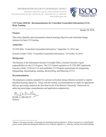
ON1 2 3 4 5 6 7 8 9 10DIAGRAM OF FUNCTIONSCUI-2TS PORTUSB12 VDCMIC INPUTMIC INPUTS12341. MIC INPUT TERMINAL BLOCKTwo channels of microphone preamplification for a stereo mic or (up to)two mono microphones. 2. TOUCHSWITCH PORTRJ45 port for connection to Clockaudio Touch Switch controls.3. USB PORTUSB streaming port (Type B) for connection to Windows or Mac PC(Type A). Also powers the CUI-2.4. 12VDC POWER INLET (OPTIONAL)Use with Clockaudio PSU 1205 (North America) or PSU 6 (Worldwide).MIC INPUTINPUTOnlyMICrequiredif running more than one Touch Switch.MIC INPUTS6FEMALE XLR(front view)MIC INPUTS
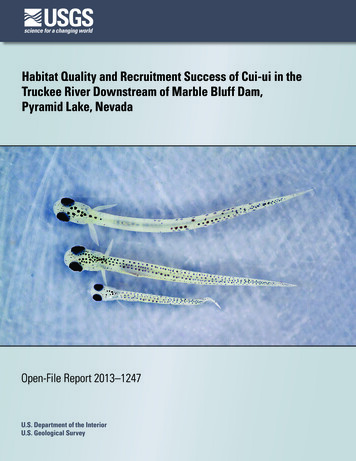
NEGATIVE (-)ON5CUI-21 2 3 4 5 6 7 8 9 1067TS PORT89USB12 VDC5. LED BRIGHTNESSMIC INPUTAdjust the brightness of the Touch Switch LEDs6. LED COLORS - MUTE COLOR SELECTIONConfigure theMIC“mute”INPUTS state color(s) of the Touch Switch LEDs7. LED COLORS - UNMUTE COLOR SELECTIONConfigure the “unmute” state color(s) of the Touch Switch LEDs.8. SETUPTOUCH SWITCH FUNCTIONSelect Push to Mute or Latch Touch Switch functionality.LED FUNCTIONSelect VU meter or mute indicator for Touch Switch LEDs.STEREO OR MONO MIC OPERATIONSelect stereo (or dual mono) or mono microphone modes.DEMO/DIAGNOSTIC MODEActivate the DEMO/DIAGNOSTIC mode.9. PREAMP GAINAdjust the amount of gain for the microphone.MIC INPUTMIC INPUTMIC INPUTSFEMALE XLR(front view)MIC INPUTS7
APPLICATION EXAMPLESThe CUI-2 is an ideal preamp and USB interface for home office or smallconferencing spaces. When used with Clockaudio microphones and TouchSwitch units, the CUI-2 serves as an audio command center for video calls,voice conferences and group chats.Use with a Clockaudio gooseneck microphone, shockmountand TS005 Touch Switch for a personal work spaceThe Clockaudio CS2S-V-RF-RGB (stereo) or CS1S-RF-RGB (mono)are ideal for huddle rooms and minimalist desks.8
0SETTING UP THE CUI-2We recommend setting up the CUI-2in the following order:1. Configure Switches2. Connect Microphones, TouchSwitch, and USB1 2 3 4 5 6 7 8 9 10ONAdjust preamp and3.LED Brightness4. Test features withDEMO/DIAGNOSTIC mode5. Mount the CUI-2ON1 2 3 4 5 6 7 8 9 10CONFIGURING THE CUI-2Use the 10 dip switches on the front panel along with the LED BRIGHTNESSand GAIN knobs to configure the CUI-2 for each specific application.MUTE & UNMUTE COLORSThe red, green and blue switches are provided to set the colors displayed ona Touch Switch when the microphone is muted or active.Use DIP SWITCHES 1-3 to select the MUTE color and DIP SWITCHES 4-6 forthe UNMUTE color. Multiple DIP SWITCHES in the ON position will yield acombination of the colors.COLOR OPTIONS REDGREENBLUEYELLOW (RED & GREEN ON)PURPLE (RED & BLUE ON) LIGHT BLUE (GREEN & BLUE ON) WHITE (ALL SWITCHES ON) NO COLOR (ALL SWITCHES OFF9
The most common use is DIP SWITCH 1 and 5 in the ON position. Thiswould show a green LED when the mic is active and a red LED when themicrophone is muted.CUI-2 CONNECTIONSConnect a Clockaudio microphone, Touch Switch, and Windows or MacPC in the manner shown below. In this example, we will use the C313-SR,SM20-RF & TS00510
TOUCH SWITCH PORT SETUPThe TS PORT allows users to connect a Touch Switch such as the TS 003or TS 005 to the CUI-2 for microphone muting and unmuting. The first 8 DIPSWITCHES and the LED BRIGHTNESS control will alter the functionality of theconnected TS Switch.TS PORT OPTIONSDIP SWITCH 7 places theTouch Switch in latch ormomentary mode.In the OFF or down position,the Touch Switch will be in1 2LATCH mode. In this mode,ONpress the switch one timeto mute the microphone.The microphone will remainmuted until the switch ispressed a second time. Thesecond press will unmute the microphone.3 4 5 6 7 8 9 10ONIn the UP or on position, the Touch Switch is in Push To Mute, or PTM mode.In this mode, the microphone(s) will mute only while the switch is touched/pressed. This mode is often used as a ‘‘Cough Mute’’.DIP SWITCH 8 determines if the LEDs on the Touch Switch display the MUTEstatus or a VU meter.When DIP SWITCH 8 is the MUTE (down) position, the LEDs on the TouchSwitch will indicate a muted or active microphone or microphones. Inthis position, the colors for both MUTE an UNMUTE are determined by DIPSWITCHES 1-6.When DIP SWITCH 8 is in the VU (up) position, the LEDs on the TS switchwill function as a VU meter.111
MIC INPUTMIC INPUTS A green LED indicates the audio input is in an acceptable range. A yellow LED indicates the audio is near clipping A red LED indicates that the microphone audio is clipping or clipping isimminent.LED BRIGHTNESSThe LED Brightness control determines thebrightness of the Touch Switch LEDs.NOTE: When turned fully counter-clockwiseto the 0 position, all LEDs will be turned off,regardless of the DIP SWITCH settings.MIC INPUTMIC INPUTS12
CONNECTING TO PC/MAC VIA USBThe CUI-2 is a plug and play USB interface. When connected to a PC or Maccomputer, the CUI-2 will show up as CUI-2 USB Mic Preamp, a two-channelinput device.Launch Windows Sound panel (on a Windows PC) or Sound from SystemPreferences (on a Mac computer) to verify the CUI-2 has installed properly.To adjust the gain of the microphone, use the gain trim knob on the CUI-2 asdescribed in the microphone setup section.Windows Sound PanelMac OS X Sound Preferences13
MIC INPUTMIC INPUTSMICROPHONE SETUPThe CUI-2 provides 2 channels of microphone amplification and USBstreaming to a connected PC or Mac computer.Connect microphone(s) to the CUI-2 with professional grade cabling. Werecommend that the cable be shielded.If using an XLR connector, wire the positive (pin 2) on the XLR to the firstterminal. The negative (pin 3) to the second terminal, and the ground (pin 1)to the third terminal. Repeat for a second microphone if using.MIC INPUTMIC INPUTMIC INPUTSFEMALE XLR(front view)ON1 2MIC INPUTSMONO MICROPHONEWhen using a single mono microphone with the CUI-2: Set DIP SWITCH 10 to the MONO (Off or DOWN) position. Connect the microphone to Channel 1 on the terminal block. In this mode, the signal on Channel 1 will be duplicated on Channel 2on the USB device. Mic input of Channel 2 will be disabled.STEREO OR DUAL MONO MICROPHONESWhen using a single stereo microphone such as the CS2S-V-RF-RGB (ordual mono microphones) with the CUI-2: Set DIP SWITCH 10 to the STEREO (ON or UP) position.Connect Mic A to Channel 1 on the terminal block.Connect Mic B to Channel 2 on the terminal block.In this mode, both Channel 1 (Left) and Channel 2 (Right) will beaccessible via USBStereo mode is only compatible with stereo capable soft codecs like Zoom.Currently, Teams and Webex are not stereo compatible and will only workwith a single microphone in mono mode.143 4 5 6 7
USE THE VU MODE TO SET GAINIf using a Clockaudio Touch Switch with the CUI-2, place the LED indicatorsin VU mode (see TS Port Setup section). In this mode, the LEDs will appeargreen when a signal is present, yellow when a signal is near clipping, andred when the signal is clipping.In VU mode, speak into the microphone(s) at a slightly elevated speechlevel. Set the microphone preamp gain trim knob so the signal is mostlygreen with infrequent peaks into yellow during louder speech testing. You donot want to see any Red.Once the gain is set properly, move DIP SWITCH 8 back to the MUTE position(DOWN or OFF). This reassigns the LEDs back to identifying the MUTE/UNMUTE state of the CUI-2.VERIFY STREAMING AND GAIN LEVELS VIA USBAfter you have adjusted the gain onthe CUI-2, verify that it is passingthe signal to a Windows or Mac PC.Connect the CUI-2 to a Windows orMac PC.Launch Windows Sound panel(on a Windows PC) or Sound fromSystem Preferences (on a Maccomputer). Verify that the input levelis satisfactory.Mac OS X Sound Preferences15
MICROPHONE PLACEMENTOptimizing the position of your microphone is key to reducing unwantedroom noise for videoconferencing and voice conferences. Lower noisewill improve intelligibility and sound quality. In a home office installation,consideration must be made for noise such as: AC unitNatural room reverbComputer fan noiseMechanical keyboard noiseDog barkingKids playing/screamingPlease keep the directionality of your microphone in mind when mountingthe microphone on your desk. Before drilling, connect your kit and testdifferent positions with a software like Zoom that will let you listen to thesignal of your microphone. This will let you test different positions andangles to optimize your sound quality before drilling in your desk.Another factor to keep in mind withnoise is proximity: the closer to thenoise source you are, the louderit will be unless you strategicallyaim the back of a directionalmicrophone (ie: cardioid) facingaway from the noise source.In the example to your left, themodular gooseneck (CA30-RF)has a knuckle-joint terminationthat will help to aim any mountedClockaudio microphone capsule toward you while rejecting keyboard noise.If you have a regular gooseneck without the knuckle-joint, try making an ‘’S’’shape like the picture above to accomplish similar results.16
Optimal microphone placement is around 12-18 inches from your mouth.If you place the microphone further you will pick up more room reflections,and room noise. Mics placed closer than 12 inches may distort.While there are amazing digital noise suppression features in your favoriteconferencing software (Zoom, Teams, etc.) or third party noise suppressionsoftware (RTX Voice) to filter out noise digitally, the best results will be foundby reducing your noise at the source with the help of optimized microphonepositioning techniques.If you have a quieter keyboard or a keyboard that is not near themicrophone, a directionalboundary layermicrophone like the CS1SRF is a good option.This will offer a lowprofile alternative to agooseneck microphonewhile providing greatintelligibility and audioquality.Please note that adirectional microphoneshould be kept at least2 inches away from other objects to maintain rear noise rejection. Anydirectional microphone placed closer than 2 inches from a surface willbecome omni-directional and lose its rear noise rejection.NOTE: Some video conferencing systems only support mono audio. It iscommon for mono conferences to use Input 1 and ignore the signal onInput 2. When using a stereo microphone, review the audio settings inyour conference software and select the stereo microphone input option ifavailable.17
DEMO/DIAGNOSTIC/TEST MODEThe DEMO mode on the CUI-2 is useful for troubleshooting or testing aninstallation. When the DEMO mode is active, the CUI-2 will: Stream a 440Hz test tone to the USB input Cycle through all the available color combinations on the Touch Switch(if installed).To activate the Test mode, slide DIP SWITCH 10 to the UP or DEMO position.The DEMO mode tone generator provides an easy way to verify USB audiois streaming properly. The tone can be identified on the input meter inthe Windows Sound panel (on a Windows PC) or Sound from SystemPreferences (on a Mac computer). If signal is present on your input meterin DEMO mode but not in NORM mode with your microphone(s) connected,please review the microphone wiring.18
MOUNTINGThe CUI-2 is most commonly mounted to the underside of a desk orconference table. When mounting the CUI-2, please consider the following: Ensure the mount point is close enough to reach the USB ports on acomputer. Mount in a secure location that will not interfere with chairs or users. Secure the CUI-2 to a flat surface with a No. 6 (included) screw througheach mounting flange.See Mechanical Drawing Section for specific dimensions.FRONT COVERIf desired, install the tamper resistant front cover after CUI-2 configurationand testing is completed. The CUI-2 front cover conceals the hardwarecontrols. To install the front cover: Partially back out the No.6 screw from the front panel flange. Install the tamper resistant front panel over the controls. Reinstall the No. 6 screw to secure the front plate and the CUI-2.19
SPECIFICATIONSAUDIO SPECIFICATIONSInput TypeBalanced and RF filteredGainVariable (10-50dB)Input Impedance2.5 KΩPhantom Power48V (always on)Terminal Block Replacement PNMolex 39500-0006EIN-122dBuSystem THD N 0.01% at any gain, input signal3dB below maximumFrequency Response20Hz - 20kHz, /- 1dB @ 40dBGainGENERAL SPECIFCATIONS20TS Control Device InputRJ45, interfaces withClockaudio TS-C1 andClockaudio Touch SwitchesPower Consumption (USB type B)2WMax Product Dimensions5.07” x 3.35” x 1.44”Mounting Slot Mounting Dimension4.625” to 4.75” (center to center)Recommended Mounting Screw#6Unit Weight0.5 lbsPackaged Weight0.8 lbsComplianceTBD
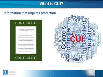
MECHANICAL .188”0.188”04.00”4.00”21
Clockaudio Ltd.Unit C, Wellington Gate, Silverthorne Way,Waterlooville, Hampshire PO7 7XY, UKTel: 44(0)23 9225-1193Fax: 44(0)23 9225 1201Email: info@Clockaudio.co.ukClockaudio North America Inc.2891 du Meunier, Unit 103, Vaudreuil-Dorion, QC,Canada J7V 8P9Toll Free: 1-888-424-9797Tel: 450-424-9797Fax: 450-424-3660Email: info@clockaudio.comClockaudio PTE Ltd.BizTech Centre, Unit # 01-02, 627A Aljunied Road,Singapore, 389842Tel: 65 67484738Fax: 65 67484428Email: info@clockaudio.com.sg22
the Touch Switch will be in LATCH mode. In this mode, press the switch one time to mute the microphone. The microphone will remain muted until the switch is pressed a second time. The second press will unmute the microphone. In the UP or on position, the Touch Switch is in Push To Mute, or PTM mode.