Transcription
C H A P T E R5Configuring POSThis chapter describes advanced packet-over-SONET/SDH (POS) interface configuration for theML-Series card. Basic POS interface configuration is included in Chapter 4, “Configuring Interfaces.”For more information about the Cisco IOS commands used in this chapter, refer to the Cisco IOSCommand Reference publication. POS operation on ONS Ethernet cards, including the ML-Series card,is described in Chapter 20, “POS on ONS Ethernet Cards.”This chapter contains the following major sections: POS on the ML-Series Card, page 5-1 Monitoring and Verifying POS, page 5-9 POS Configuration Examples, page 5-11POS on the ML-Series CardEthernet and IP data packets need to be framed and encapsulated into SONET/SDH frames for transportacross the SONET/SDH network. This framing and encapsulation process is known as POS and is donein the ML-Series card. Chapter 20, “POS on ONS Ethernet Cards,” explains POS in greater detail.The ML-Series card takes the standard Ethernet ports on the front of the card and the virtual POS portsand includes them all as switch ports. Under Cisco IOS, the POS port is an interface similar to the otherEthernet interfaces on the ML-Series card. It is usually used as a trunk port. Many standard Cisco IOSfeatures, such as IEEE 802.1 Q VLAN configuration, are configured on the POS interface in the samemanner as on a standard Ethernet interface. Other features and configurations are done strictly on thePOS interface. The configuration of features limited to POS ports is shown in this chapter.ML-Series SONET and SDH Circuit SizesSONET is an American National Standards Institute (ANSI) standard (T1.1051988) for optical digitaltransmission at hierarchical rates from 51.840 Mbps (STS-1) to 2.488 Gbps (STS-48) and greater. SDHis the international standard for optical digital transmission at hierarchical rates from 155.520 Mbps(STM-1) to 2.488 Gbps (STM-16) and greater.Both SONET and SDH are based on a structure that has a basic frame and speed. The frame format usedby SONET is the synchronous transport signal (STS), with STS-1 being the base level signal at51.84 Mbps. A STS-1 frame can be carried in an OC-1 signal. The frame format used by SDH is thesynchronous transport module (STM), with STM-1 being the base level signal at 155.52 Mbps. A STM-1frame can be carried in an OC-3 signal.Cisco ONS 15454 and Cisco ONS 15454 SDH Ethernet Card Software Feature and Configuration Guide, R8.05-1
Chapter 5 Configuring POSVCATBoth SONET and SDH have a hierarchy of signaling speeds. Multiple lower level signals can bemultiplexed together to form higher level signals. For example, three STS-1 signals can be multiplexedtogether to form a STS-3 signal, and four STM-1 signals can be multiplexed together to form a STM-4signal.SONET circuit sizes are defined as STS-n, where n is a multiple of 51.84 Mbps and n is equal to orgreater than 1. SDH circuit sizes are defined as STM-n, where n is a multiple of 155.52 Mbps and n isequal to or greater than 0. Table 5-1 shows STS and STM line rate equivalents.Table 5-1SONET STS Circuit Capacity in Line Rate MbpsSONET Circuit SizeSDH Circuit SizeLine Rate in MbpsSTS-1 (OC-1)VC-3152 MbpsSTS-3c (OC-3)STM-1 (VC4)156 MbpsSTS-6c (OC-6)STM-2 (VC4-2c)311 MbpsSTS-9c (OC-9)STM-3 (VC4-3c)466 MbpsSTS-12c (OC-12)STM-4 (VC4-4c)622 MbpsSTS-24c (OC-24)STM-8 (VC4-8c)1244 Mbps (1.24 Gbps)1. VC-3 circuit support requires an XC-VXx or XC-VCX-10G card to be installed.For step-by-step instructions on configuring an ML-Series card SONET STS circuit, refer to the “CreateCircuits and VT Tunnels” chapter of the Cisco ONS 15454 Procedure Guide. For step-by-stepinstructions on configuring an ML-Series card SDH STM circuit, refer to the “Create Circuits andTunnels” chapter of the Cisco ONS 15454 SDH Procedure Guide.VCATVCAT significantly improves the efficiency of data transport over SONET/SDH by grouping thesynchronous payload envelopes (SPEs) of SONET/SDH frames in a nonconsecutive manner into VCATgroups. VCAT group circuit bandwidth is divided into smaller circuits called VCAT members. Theindividual members act as independent circuits.Intermediate nodes treat the VCAT members as normal circuits that are independently routed andprotected by the SONET/SDH network. At the terminating nodes, these member circuits are multiplexedinto a contiguous stream of data. VCAT avoids the SONET/SDH bandwidth fragmentation problem andallows finer granularity for provisioning of bandwidth services.The ONS 15454 SONET and ONS 15454 SDH ML-Series card VCAT circuits must also be routed overcommon fiber and be both bidirectional and symmetric. Only high order (HO) VCAT circuits aresupported. The ML-Series card supports a maximum of two VCAT groups, with each groupcorresponding to one of the POS ports. Each VCAT group can contain two circuit members. A VCATcircuit originating from an ML-Series card must terminate on another ML-Series card or a CE-Seriescard. Table 5-2 shows supported VCAT circuit sizes for the ML-Series.Cisco ONS 15454 and Cisco ONS 15454 SDH Ethernet Card Software Feature and Configuration Guide, R8.05-2
Chapter 5 Configuring POSSW-LCASTable 5-2VCAT Circuit Sizes Supported by ML100T-12, ML100X-8, and ML1000-2 CardsSONET VCAT Circuit SizeSDH VCAT Circuit 4c-2vFor step-by-step instructions on configuring an ML-Series card SONET VCAT circuit, refer to the“Create Circuits and VT Tunnels” chapter of the Cisco ONS 15454 Procedure Guide. For step-by-stepinstructions on configuring an ML-Series card SDH VCAT circuit, refer to the “Create Circuits andTunnels” chapter of the Cisco ONS 15454 SDH Procedure Guide. For more general information onVCAT circuits, refer to the “Circuits and Tunnels” chapter of the Cisco ONS 15454 Reference Manualor the Cisco ONS 15454 SDH Reference Manual.NoteML-Series card POS interfaces normally send an alarm for signal label mismatch failure in the ONS15454 STS path overhead (PDI-P) to the far end when the POS link goes down or when RPR wraps.ML-Series card POS interfaces do not send PDI-P to the far-end when PDI-P is detected, when a remotedefection indication alarm (RDI-P) is being sent to the far end, or when the only defects detected aregeneric framing procedure (GFP)-loss of frame delineation (LFD), GFP client signal fail (CSF), virtualconcatenation (VCAT)-loss of multiframe (LOM), or VCAT-loss of sequence (SQM).NoteFor nodes not connected by DCC (open ended nodes), VCAT must be configured through TL-1.SW-LCASA link capacity adjustment scheme (LCAS) increases VCAT flexibility by allowing the dynamicreconfiguration of VCAT groups without interrupting the operation of noninvolved members. Softwarelink capacity adjustment scheme (SW-LCAS) is the software implementation of a LCAS-type feature.SW-LCAS differs from LCAS because it is not errorless and uses a different handshaking mechanism.SW-LCAS on the ONS 15454 SONET/SDH ML-Series cards allows the automatic addition or removalof a VCAT group member in the event of a failure or recovery on a two-fiber bidirectional line switchedring (BLSR). The protection mechanism software operates based on ML-Series card link events.SW-LCAS allows service providers to configure VCAT member circuits on the ML-Series as protectionchannel access (PCA) circuits. This PCA traffic is dropped in the event of a protection switch, but issuitable for excess or noncommited traffic and can double the total available bandwidth on the circuit.For step-by-step instructions on configuring SW-LCAS, refer to the “Create Circuits and VT Tunnels”chapter of the Cisco ONS 15454 Procedure Guide or the “Create Circuits and Tunnels” chapter of theCisco ONS 15454 SDH Procedure Guide. For more general information on SW-LCAS, refer to the“Circuits and Tunnels” chapter of the Cisco ONS 15454 Reference Manual or theCisco ONS 15454 SDH Reference Manual.Cisco ONS 15454 and Cisco ONS 15454 SDH Ethernet Card Software Feature and Configuration Guide, R8.05-3
Chapter 5 Configuring POSFraming Mode, Encapsulation, and CRC SupportFraming Mode, Encapsulation, and CRC SupportThe ML-Series cards on the ONS 15454 and ONS 15454 SDH support two modes of the POS framingmechanism, GFP-F framing and HDLC framing (default). The framing mode, encapsulation, and CRCsize on source and destination POS ports must match for a POS circuit to function properly. Chapter 20,“POS on ONS Ethernet Cards,” explains the framing mechanisms, encapsulations, and cyclicredundancy check (CRC) bit sizes in detail.Supported encapsulation and CRC sizes for the framing types are detailed in Table 5-3.Table 5-3ML-SeriesSupported Encapsulation, Framing, and CRC Sizes for ML-Series Cards on theONS 15454 and ONS 15454 SDHEncapsulations forHDLC FramingCRC Sizes for HDLCFramingEncapsulations forGFP-F FramingCRC Sizes forGFP-F FramingLEX (default)16-bitLEX (default)32-bit (default)Cisco HDLC32-bit (default)Cisco HDLCPPP/BCPNotePPP/BCPML-Series card POS interfaces normally send PDI-P to the far-end when the POS link goes down or RPRwraps. ML-Series card POS interfaces do not send PDI-P to the far-end when PDI-P is detected, whenRDI-P is being sent to the far-end or when the only defects detected are GFP LFD, GFP CSF, VCATLOM or VCAT SQM.Configuring POS Interface Framing ModeYou configure framing mode on an ML-Series card only through CTC. For more information onconfiguring framing mode in CTC, see Chapter 2, “CTC Operations.”Configuring POS Interface Encapsulation TypeThe default Cisco EoS LEX is the primary encapsulation of ONS Ethernet cards. This encapsulation isused under HDLC framing with the protocol field set to the values specified in Internet Engineering TaskForce (IETF) Request For Comments (RFC) 1841. Under GFP-F framing, the Cisco IOS CLI also usesthe keyword lex. With GFP-F framing, the lex keyword is used to represent standard mapped Ethernetover GFP-F according to ITU-T G.7041.To configure the encapsulation type for a ML-Series card, perform the following steps beginning inglobal configuration mode:CommandPurposeStep 1Router(config)# interface pos numberActivates interface configuration mode toconfigure the POS interface.Step 2Router(config-if)# shutdownManually shuts down the interface. Encapsulationchanges on POS ports are allowed only when theinterface is shut down (ADMIN DOWN).Cisco ONS 15454 and Cisco ONS 15454 SDH Ethernet Card Software Feature and Configuration Guide, R8.05-4
Chapter 5 Configuring POSFraming Mode, Encapsulation, and CRC SupportStep 3CommandPurposeRouter(config-if)# encapsulation typeSets the encapsulation type. Valid values are: hdlc—Cisco HDLC lex—(default) LAN extension, specialencapsulation for use with Cisco ONSEthernet line cards. When the lex keyword isused with GFP-F framing it is standardMapped Ethernet over GFP-F according toITU-T G.7041. ppp—Point-to-Point ProtocolStep 4Router(config-if)# no shutdownRestarts the shutdown interface.Step 5Router(config)# endReturns to privileged EXEC mode.Step 6Router# copy running-config startup-config(Optional) Saves configuration changes toNVRAM.Configuring POS Interface CRC Size in HDLC FramingTo configure additional properties to match those of the interface at the far end, perform the followingsteps, beginning in global configuration mode:CommandPurposeStep 1Router(config)# interface pos numberActivates interface configuration mode toconfigure the POS interface.Step 2Router(config-if)# crc {16 32}Sets the CRC value for HDLC framing. If thedevice to which the POS module is connected doesnot support the default CRC value of 32, set bothdevices to use a value of 16.NoteThe CRC value is fixed at a value of 32under GFP-F framing.Step 3Router(config-if)# endReturns to the privileged EXEC mode.Step 4Router# copy running-config startup-config(Optional) Saves configuration changes toNVRAM.Setting the MTU SizeTo set the maximum transmission unit (MTU) size, perform the following steps, beginning in globalconfiguration mode:CommandPurposeStep 1Router(config)# interface pos numberActivates interface configuration mode toconfigure the POS interface.Step 2Router(config-if)# mtu bytesConfigures the MTU size up to a maximum of9000 bytes. See Table 5-4 for default MTU sizes.Cisco ONS 15454 and Cisco ONS 15454 SDH Ethernet Card Software Feature and Configuration Guide, R8.05-5
Chapter 5 Configuring POSSONET/SDH AlarmsCommandPurposeStep 3Router(config-if)# endReturns to the privileged EXEC mode.Step 4Router# copy running-config startup-config(Optional) Saves configuration changes toNVRAM.Table 5-4 shows the default MTU sizes.Table 5-4Default MTU SizeEncapsulation TypeDefault SizeLEX (default)1500HDLC4470PPP4470Configuring Keep Alive MessagesTo configure keep alive messages for the ML-Series card, perform the following steps beginning inglobal configuration mode:CommandPurposeStep 1Router(config)# interface posnumberEnters interface configuration mode and specifies the POSinterface to configure.Step 2Router(config-if)# [no] keepaliveConfigures keep alive messages.Keep alive messages are on by default and are recommended,but not required.The no form of this command turns off keep alive messages.Step 3Router(config-if)# endReturns to the privileged EXEC mode.Step 4Router# copy running-configstartup-config(Optional) Saves configuration changes to NVRAM.SONET/SDH AlarmsThe ML-Series cards report SONET/SDH alarms under both Cisco IOS and CTC/TL1. A number of pathalarms are reported in the Cisco IOS console. Configuring Cisco IOS console alarm reporting has noeffect on CTC alarm reporting. The “Configuring SONET/SDH Alarms” section on page 5-7 specifiesthe alarms reported to the Cisco IOS console.CTC/TL1 has sophisticated SONET/SDH alarm reporting capabilities. As a card in the ONS node, theML-Series card reports alarms to CTC/TL-1 like any other ONS card. On the ONS 15454 SONET, theML-Series card reports Telcordia GR-253 SONET alarms in the Alarms panel of CTC. For moreinformation on alarms and alarm definitions, refer to the “Alarm Troubleshooting” chapter of theCisco ONS 15454 Troubleshooting Guide or the Cisco ONS 15454 SDH Troubleshooting Guide.Cisco ONS 15454 and Cisco ONS 15454 SDH Ethernet Card Software Feature and Configuration Guide, R8.05-6
Chapter 5 Configuring POSSONET/SDH AlarmsCTC/TL1Alarmshas sophisticated SONET/SDH alarm reporting capabilities. As a card in the ONS node, theConfiguring SONET/SDHML-Series card reports alarms to CTC/TL-1 like any other ONS card. On the ONS 15454 SONET, theML-Seriescard reportsalarms inthethereportingAlarms panelof CTC. Formoreon theAll SONET/SDHalarmsTelcordiaappear byGR-253default SONETBut to provisionof heCisco IOS CLI, perform the following steps beginning in global configuration mode:Cisco ONS 15454 Troubleshooting Guide or the Cisco ONS 15454 SDH Troubleshooting config)# interface1PurposeEnters interface configuration mode and specifies the POSinterfaceto configure.All SONET/SDH alarms are logged on theCisco IOSCLI by default. But to provision or disable theposnumberStep 2Router(config-if)#pos alarmsreporton the Ciscoreportingof SONET/SDHIOSCLI, performsteps beginningin globalPermitsconsoleloggingtheof followingselected SONET/SDHalarms.{all encapmode: pais plop ppdi Use the no form of the command to disable reporting of aconfiguration pplm prdi ptim puneq specific alarm.sd-ber-b3 sf-ber-b3}CommandStep 1Router(config)# interface posnumberStep 2Router(config-if)# pos report{all encap pais plop ppdi pplm prdi ptim puneq sd-ber-b3 sf-ber-b3}Step 3Router(config-if)# endStep 4Router# copy running-configstartup-configStep 3The alarms are as follows:Purpose n mode and specifies the POSinterfaceto configure. encap—Pathencapsulation mismatchPermitslogging alarmof selectedSONET/SDH pais—Pathindicationsignal alarms. Use the noform of the command to disable reporting of a specific alarm. plop—Path loss of pointerThe alarms are as follows: ppdi—Path payload defect indication all—All alarms/signals pplm—Payload label, C2 mismatch encap—Path encapsulation mismatch prdi—Path remote defect indication pais—Path alarm indication signal ptim—Path trace identifier mismatch plop—Path loss of pointer puneq—Path label equivalent to zero ppdi—Path payload defect indication sd-ber-b3—PBIP BER in excess of SD threshold pplm—Payload label, C2 mismatch sf-ber-b3—PBIP BER in excess of SF threshold prdi—Path remote defect indicationReturns to the privileged EXEC mode. ptim—Path trace identifier mismatch(Optional) Saves configuration changes to NVRAM. puneq—Path label equivalent to zero sd-ber-b3—PBIP BER in excess of SD thresholdTo determine which alarms are reported on the POS interface and to display the bit error rate (BER) sf-ber-b3—PBIPin “Monitoringexcess of SFandthresholdthresholds, use the show controllers pos command,as describedBERin theVerifying POS”Router(config-if)#sectionon page 5-9. endReturns to the privileged EXEC mode.Step 4Router# copy running-configstartup-configNoteCisco IOS alarm reporting commands apply only to the Cisco IOS CLI. SONET/SDH alarms reportedto the TCC2/TCC2P are not affected.To determine which alarms are reported on the POS interface and to display the bit error rate (BER)thresholds, use the show controllers pos command, as described in the “Monitoring and Verifying POS”section on page 5-9.(Optional) Saves configuration changes to NVRAM.Configuring SONET/SDH Delay TriggersNoteYou can set path alarms listed as triggers to bring down the line protocol of the POS interface. When youCiscoIOSthealarmapplythe CiscoIOSforCLI.configurepathreportingalarms ascommandstriggers, youcanonlyalsotospecifya delaytheSONET/SDHtriggers usingalarmsthe lay command. You can set the delay from 200 to 2000 ms. If you do not specify a time interval, thedefault delay is set to 200 ms.Cisco ONS 15454 and Cisco ONS 15454 SDH Ethernet Card Software Feature and Configuration Guide, R8.05-7
Chapter 5 Configuring POSC2 Byte and ScramblingTo configure path alarms as triggers and specify a delay, perform the following steps beginning in globalconfiguration mode:CommandPurposeStep 1Router(config)# interface posnumberEnters interface configuration mode and specifies the POSinterface to configure.Step 2Router(config-if)# pos triggerdefect {all ber sf b3 encap pais plop ppdi pplm prdi ptim puneq}Configures certain path defects as triggers to bring down thePOS interface. The configurable triggers are as follows: all—All link down alarm failures ber sd b3—PBIP BER in excess of SD thresholdfailure ber sf b3—PBIP BER in excess of SD threshold failure(default) encap—Path Signal Label Encapsulation Mismatchfailure (default) pais—Path Alarm Indication Signal failure (default) plop—Path Loss of Pointer failure (default) ppdi—Path Payload Defect Indication failure (default) pplm—Payload label mismatch path (default) prdi—Path Remote Defect Indication failure (default) ptim—Path Trace Indicator Mismatch failure (default) puneq—Path Label Equivalent to Zero failure (default)Step 3Router(config-if)# pos triggerdelay millisecondSets waiting period before the line protocol of the interfacegoes down. Delay can be set from 200 to 2000 ms. If no timeintervals are specified, the default delay is set to 200 ms.Step 4Router(config-if)# endReturns to the privileged EXEC mode.Step 5Router# copy running-configstartup-config(Optional) Saves configuration changes to NVRAM.C2 Byte and ScramblingOne of the overhead bytes in the SONET/SDH frame is the C2 byte. The SONET/SDH standard definesthe C2 byte as the path signal label. The purpose of this byte is to communicate the payload type beingencapsulated by the SONET framing overhead (FOH). The C2 byte functions similarly to EtherType andLogical Link Control (LLC)/Subnetwork Access Protocol (SNAP) header fields on an Ethernet network;it allows a single interface to transport multiple payload types simultaneously. The C2 byte is notconfigurable. Table 5-5 provides C2 byte hex values.Table 5-5C2 Byte and Scrambling Default ValuesSignal LabelSONET/SDH Payload Contents0x01LEX Encapsulation with 32-bit CRC with or without scrambling0x05LEX Encapsulation with 16-bit CRC with or without scrambling0xCFCisco HDLC or PPP/BCP without scramblingCisco ONS 15454 and Cisco ONS 15454 SDH Ethernet Card Software Feature and Configuration Guide, R8.05-8
Chapter 5 Configuring POSMonitoring and Verifying POSTable 5-5C2 Byte and Scrambling Default Values (continued)Signal LabelSONET/SDH Payload Contents0x16Cisco HDLC or PPP/BCP with scrambling0x1BGFP-FThird-Party POS Interfaces C2 Byte and Scrambling ValuesIf a Cisco POS interface fails to come up when connected to a third-party device, confirm the scramblingand cyclic redundancy check (CRC) settings as well as the advertised value in the C2 byte. On routersfrom Juniper Networks, configuring RFC 2615 mode sets the following three parameters: Scrambling enabled C2 value of 0x16 CRC-32Previously, when scrambling was enabled, these third-party devices continued to use a C2 value of 0xCF,which did not properly reflect the scrambled payload.Configuring SPE ScramblingSPE scrambling is on by default. To configure POS SONET/SDH Payload (SPE) scrambling, performthe following steps, beginning in global configuration mode:CommandPurposeStep 1Router(config)# interface posnumberEnters interface configuration mode and specifies the POSinterface to configure.Step 2Router(config-if)# no posscramble-speDisables payload scrambling on the interface. Payloadscrambling is on by default.Step 3Router(config-if)# no shutdownEnables the interface with the previous configuration.Step 4Router(config-if)# endReturns to the privileged EXEC mode.Step 5Router# copy running-configstartup-config(Optional) Saves configuration changes to NVRAM.Monitoring and Verifying POSThe show controller pos [0 1] command (Example 5-1) outputs the receive and transmit values and theC2 value. Thus, changing the value on the local end does not change the value in the show controllercommand output.Example 5-1show controller pos [0 1] CommandML Series# sh controllers pos 0Interface POS0Hardware is Packet/Ethernet over SonetFraming Mode: HDLCCisco ONS 15454 and Cisco ONS 15454 SDH Ethernet Card Software Feature and Configuration Guide, R8.05-9
Chapter 5 Configuring POSMonitoring and Verifying POSConcatenation: CCATAlarms reportable to CLI: PAIS PLOP PUNEQ PTIM PPLM ENCAP PRDI PPDI BER SF B3 BER SD B3VCAT OOU TPT LOM SQMLink state change defects: PAIS PLOP PUNEQ PTIM PPLM ENCAP PRDI PPDI BER SF B3Link state change time: 200 (msec)*************** Path ***************Circuit state: ISPAIS 0PLOP 0PRDI 0PTIM 0PPLM 0PUNEQ 0PPDI 0PTIU 0BER SF B3 0BER SD B3 0BIP(B3) 0REI 0NEWPTR 0PSE 0NSE 0ENCAP 0Active Alarms : PAISDemoted Alarms: NoneActive Defects: PAISDOS FPGA channel number : 0Starting STS (0 based): 0VT ID (if any) (0 based) : 255Circuit size: STS-3cRDI Mode: 1 bitC2 (tx / rx): 0x01 / 0x01Framing: SONETPath TraceMode: offTransmit String :Expected String :Received String :Buffer: StableRemote hostname :Remote interface:Remote IP addr :B3 BER thresholds:SFBER 1e-4,SDBER 1e-70 total input packets, 0 post-HDLC bytes0 input short packets, 0 pre-HDLC bytes0 input long packets , 0 input runt packets0 input CRCerror packets , 0 input drop packets0 input abort packets0 input packets dropped by ucode0 total output packets, 0 output pre-HDLC bytes0 output post-HDLC bytesCarrier delay is 200 msecThe show interface pos {0 1} command (Example 5-2) shows scrambling.Example 5-2show interface pos [0 1] CommandML Series# show interface pos 0POS0 is administratively down, line protocol is downHardware is Packet/Ethernet over Sonet, address is 0011.2130.b340 (bia 0011.2130.b340)MTU 1500 bytes, BW 145152 Kbit, DLY 100 usec,reliability 255/255, txload 1/255, rxload 1/255Encapsulation: Cisco-EoS-LEX, crc 32, loopback not setKeepalive set (10 sec)Scramble enabledARP type: ARPA, ARP Timeout 04:00:00Last input 01:21:02, output never, output hang neverLast clearing of "show interface" counters 00:12:01Input queue: 0/75/0/0 (size/max/drops/flushes); Total output drops: 0Queueing strategy: fifoOutput queue: 0/40 (size/max)5 minute input rate 0 bits/sec, 0 packets/sec5 minute output rate 0 bits/sec, 0 packets/sec0 packets input, 0 bytesCisco ONS 15454 and Cisco ONS 15454 SDH Ethernet Card Software Feature and Configuration Guide, R8.05-10
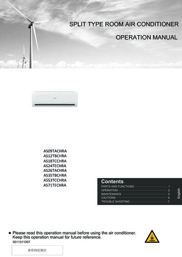
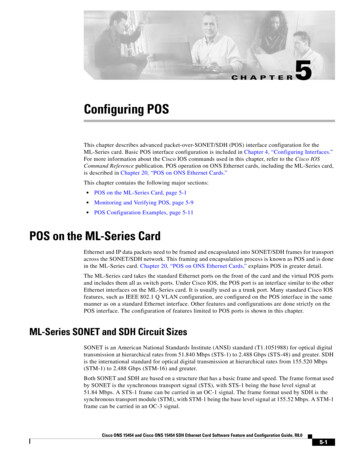
Chapter 5 Configuring POSPOS Configuration ExamplesReceived 0 broadcasts (0 IP multicast)0 runts, 0 giants, 0 throttles0 parity0 input errors, 0 CRC, 0 frame, 0 overrun, 0 ignored0 input packets with dribble condition detected0 packets output, 0 bytes, 0 underruns0 output errors, 0 applique, 0 interface resets0 babbles, 0 late collision, 0 deferred0 lost carrier, 0 no carrier0 output buffer failures, 0 output buffers swapped out0 carrier transitionsPOS Configuration ExamplesThe following sections show ML-Series card POS configuration examples for connecting to other ONSEthernet cards and POS-capable routers. These examples are only some of the ML-Series cardconfigurations available to connect to other ONS Ethernet cards and POS-capable routers. For morespecifics about the POS characteristics of ONS Ethernet cards, see Chapter 20, “POS on ONS EthernetCards.”ML-Series Card to ML-Series CardFigure 5-1 illustrates a POS configuration between two ONS 15454 or ONS 15454 SDH ML-Seriescards.Figure 5-1ML-Series Card to ML-Series Card POS ConfigurationONS 15454with ML100T-12ML Series AONS 15454with ML100T-12ML Series Bpos 0192.168.2.1pos 0SONET/SDHfast ethernet 0192.168.3.183127fast ethernet 0192.168.1.1192.168.2.2Example 5-3 shows the commands associated with the configuration of ML-Series card A.Example 5-3ML-Series Card A Configurationhostname ML Series A!interface FastEthernet0ip address 192.168.1.1 255.255.255.0!interface POS0ip address 192.168.2.1 255.255.255.0crc 32pos flag c2 1!router ospf 1Cisco ONS 15454 and Cisco ONS 15454 SDH Ethernet Card Software Feature and Configuration Guide, R8.05-11
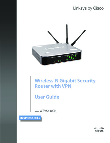
Chapter 5 Configuring POSML-Series Card to Cisco 12000 GSR-Series Routerlog-adjacency-changesnetwork 192.168.1.0 0.0.0.255 area 0network 192.168.2.0 0.0.0.255 area 0Example 5-4 shows the commands associated with the configuration of ML Series B.Example 5-4ML-Series Card B Configurationhostname ML Series B!interface FastEthernet0ip address 192.168.3.1 255.255.255.0!interface POS0ip address 192.168.2.2 255.255.255.0crc 32pos flag c2 1!router ospf 1log-adjacency-changesnetwork 192.168.2.0 0.0.0.255 area 0network 192.168.3.0 0.0.0.255 area 0!ML-Series Card to Cisco 12000 GSR-Series RouterFigure 5-2 illustrates a POS configuration between an ML-Series card and a Cisco 12000 GSR-Seriesrouter. PPP/BCP encapsulation or Cisco HDLC encapsulation may be used for interoperation.Figure 5-2ML-Series Card to Cisco 12000 Series Gigabit Switch Router (GSR) POS ConfigurationONS 15454with ML100T-12Cisco 12000 SeriesGigabit Switch Router(GSR)pos 1/0ML Series Apos 0192.168.2.1SONET/SDHfast ethernet 0192.168.3.183126fast ethernet 0192.168.1.1192.168.2.2Example 5-5 shows the commands associated with configuration of ML-Series card A.Example 5-5ML-Series Card A Configurationhostname ML Series A!interface FastEthernet0ip address 192.168.1.1 255.255.255.0!!interface POS0ip address 192.168.2.1 255.255.255.0encapsulation pppCisco ONS 15454 and Cisco ONS 15454 SDH Ethernet Card Software Feature and Configuration Guide, R8.05-12
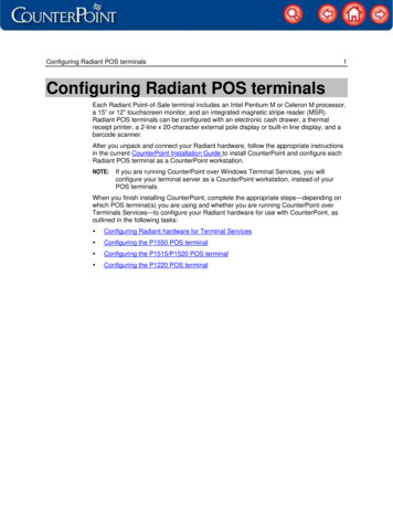
Chapter 5 Configuring POSML-Series Card to G-Series Cardcrc 32!router ospf 1log-adjacency-changesnetwork 192.168.1.0 0.0.0.255 area 0network 192.168.2.0 0.0.0.255 area 0Example 5-6 shows the commands associated with the configuration of the GSR-12000.Example 5-6GSR-12000 Configurationhostname GSR!interface FastEthernet1/0ip address 192.168.3.1 255.255.255.0!interface POS2/0ip address 192.168.2.2 255.255.255.0crc 32encapsulation PPPpos scramble-atm!router ospf 1log-adjacency-changesnetwork 192.168.2.0 0.0.0.255 area 0network 192.168.3.0 0.0.0.255 area 0!The default encapsulation for the ML-Series card is LEX and the corresponding default MTU is1500 bytes. When connecting to an external POS device, it is important to ensure that both theML-Series switch and the external device uses the same configuration for the parameters listed inTable 5-6.Table 5-6ML-Series Parameter Configuration for Connection to a Cisco 12000 fault encapsulation on the Cisco12000 GSR Series is HDLC, which is supported by theorML-Series. PPP is also supported by both the ML-SeriesRouter(config-if)# encapsulation hdlc card and the Cisco 12000 GSR Series.Router(config-if)# encapsulation pppThe Cisco 12000 GSR Series does not support LEX,which is the default encapsulation on the ML-Seriescard.Router(config-if)# show controllerposC2 Byte—Use the show controller pos command toverify that the transmit and receive C2 values are thesame.Router(config-if)# pos flag c2 valueSets the C2 byte value. Valid choices are 0 to 255(decimal). The default value is 0x01 (hex) for LEX.ML-Series Card to G-Series CardFigure 5-3 illustrates a POS configuration between an ML-Series card and a G-Series card.Cisco ONS 15454 and Cisco ONS 15454 SDH Ethernet Card Software Feature and Configuration Guide, R8.05-13
Chapter 5 Configuring POSML-Series Card to ONS 15310 ML-100T-8 CardFigure 5-3ML-Series Card to G-Series Card POS ConfigurationONS 15454with ML100T-12ONS 15454with G-SeriesML Series Apos 0192.168.2.1SONET/SDHfast ethernet 0192.168.1.183125EthernetExample 5-7 shows the commands associated with the configuration of ML-Series card A.Example 5-7ML-Series Card A Configurationhostname ML Series A!interface FastEthe
POS on the ML-Series Card, page 5-1 † Monitoring and Verifying POS, page 5-9 † POS Configuration Examples, page 5-11 POS on the ML-Series Card Ethernet and IP data packets need to be framed and encapsulated into SON ET/SDH frames for transport across the SONET/SDH network. This framing and en capsulation process is known as POS and is done