Transcription
POS NVR System StructureTable of Contents1.1 “POS NVR” mode . 21.1.1 Introduction . 21.1.2 NVR Configuration . 31.1.3 Network POS NVR . 81.1.4 RS-232 POS (Serial Port) NVR. 91.1.5 Product selection . 101.2 “iVMS 4200 POSNVR POS” mode . 111.2.1 Introduce . 111.2.2 Configuration . 111.2.3 Product selection . 141 / 14
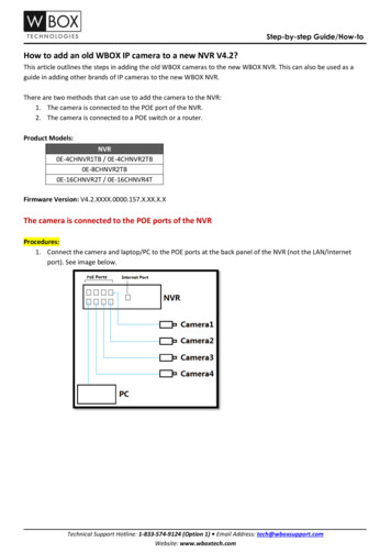
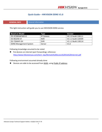
1POS NVR System StructureFig.1 POS NVR System structure of the POS application1.1 “POS NVR” mode1.1.1 IntroductionCurrently there are two ways to connect NVR with POS terminals, via network or viaserial port.For example: The NVR initiates the connection to the POS server for the POS datacommunications between POS server camera.2 / 14
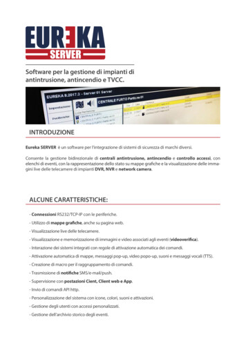
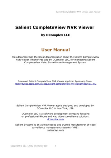
Fig.2 Basic network connection with cameraHow to realize the connection is mainly based on the type of POS machine. It’s veryimportant that what type of POS machine is adopted. The following is POS NVR severwith model introduction.1.1.2 NVR ConfigurationWe need to configure the NVR firstly.1.Login the NVR on the local NVR page, select “system”- ” POS”, and edit a POSchannel.Fig.3 POS configuration page2.Select a connection type. If the connection type is UDP Reception, you also need toconfigure the UDP Reception parameters.3 / 14
Fig.4 POS connection parameter setting 1Fig.5 POS connection parameter setting 23. Then, select the overlay mode, font size, overlay time(s), font color in this page and soon.4 / 14
Fig.6 POS overlay setting4. After setting the GUI of NVR, we should set the parameter in the Convert Tester.Including protocol, local host IP, local host port and then click ‘connect’.Fig.7 POS Convert Tester—Net setting 15. We should fill in the Remote IP as NVR’s IP, Port, the POS content and click ‘Send’ inthe Convert Tester.5 / 14
Fig.8 POS Convert Tester—Net setting 26. Then the POS overlay you set will display to the live view local page. Youcan choose to display or not in POS configuration page or live view page.Fig.9 POS overlay setting6 / 14
Fig.10 POS overlay setting in living view7. Record configuration: Enable the POS schedule in the Storage. And click “edit” tocheck the day is POS record.Fig.11 POS local record configuration18. Playback the POS channel in the local NVR playback page. The POS record bar isred as an event record. You can also click Disable POS overlay .Please refer to the belowpicture:7 / 14
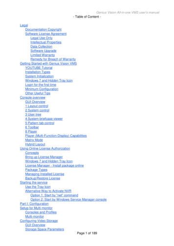
Fig.12 POS Playback Main POS parameter introduction; POS Protocol: At present, there are four kinds of compatible protocols:Universal Protocol, EPSON, AVE, NUCLEUS.POS Settings:Overlay Channel: It can show most half of the POS cameras. Select the correctchannel, you can overlay the information on it.Connection ways:Network connection (TCP, UDP, multicast, Sniff)Serial Port connection (RS-232)USB connection (USB to 232)Main POS Configuration tips: POS only overlay to the main stream. All the streams are stored in the disk, there is a control switch when playback, wecan choose to show the overlay or not. The overlay is not in the stream.1.1.3 Network POS NVRFor example: We based on TCP Reception type, NVR will initialize the connectionbetween camera and POS terminal for POS data transmission. The topology as shown inFig.12Fig.12.8 / 14
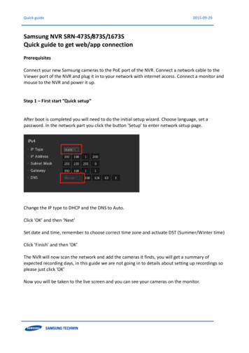
Fig.13 Network POS with NVR topology1.1.4 RS-232 POS (Serial Port) NVRTo RS-232 POS, there are three connection ways.1) POS machine connect to the NVR, the topology usually like this below:Fig.14 RS-323 POS with DVR topology12) Also, we usually will see the IO server in this mode. The POS machine connect to theIO server, the IO server turn 232 signals into network signals, the topology usually like thisbelow:9 / 14
Fig.15 RS-323 POS with DVR topology23) Use RS-232 to USB convertor, there is an extra RS-232 hardware with the USB toconnect to the NVR, the port in convertor and POS are one to one correspondence, POS1should be connected to port1 of convertor. The topology like this below:Fig.16 RS-323 POS with NVR topology21.1.5 Product selectionTable 4 Product ListProducProducttModelDescription10 / 14Image
1.Support POS rule configuration2.Support POS local live view, recordNVRI series NVRlocal playback3.Support POS event playback, backup4. It can support half of the channels tooverlay the POS information.1.2 “iVMS 4200 POSNVR POS” mode1.2.1 IntroduceWith high compatibility and wide adaption, the iVMS-4200 can manage analog, IP andhybrid signal devices; it can access to the devices of different network environment namelyLAN, WAN, cable or wireless connection. For example, we add the POS to the NVR, thenwe use the following topology:Fig.17 “iVMS 4200 POSNVR POS” mode topology1.2.2 Configuration1. Firstly, we need to keep the NVR with cameras online; then, we can add the device inthe 4200, do the configuration in the 4200 configuration page.11 / 14
Fig.18 “iVMS 4200 “maintenance management page2. Select the POS NVR, click to open the device remote configuration page, click the POStab to set the parameters.Fig.19 Remote configuration page12 / 14
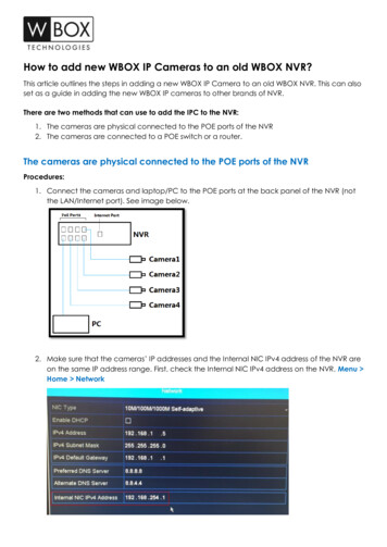
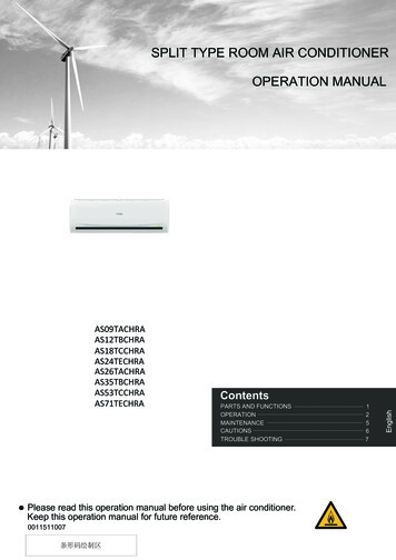
3. Live view the test overlay.Fig.20 Live view the test overlay4. Record configuration: configure the event record in the storage schedule page.Fig.21 Storage schedule configuration5. You can search the record by key word, such as: enter the keywords to filter in a periodof time. Enter Remote Playback firstly, and then click POS playback. Enter the keywords,click Search, and you can search the POS video including the keywords.13 / 14
Fig.22 POS playbackFig.23 POS keywords playback1.2.3 Product selectionTable 5 Product ListProductiVMS-4200Product ModelV2.7.1.4build20180403Description1.Support configure NVR’s POS parameter2.Suppot POS live view and playback3.Support search POS video14 / 14
1 POS NVR System Structure Fig.1 POS NVR System structure of the POS application 1.1 "POS NVR" mode 1.1.1 Introduction Currently there are two ways to connect NVR with POS terminals, via network or via serial port. For example: The NVR initiates the connection to the POS server for the POS data communications between POS server camera.