Transcription
INL/RPT-22-67704Revision 0Net-Zero Microgrid Program Project Report:Small Reactors in MicrogridsAugust 2022Technoeconomic AnalysisBikash Poudel, Timothy McJunkin, and Ning KangIdaho National LaboratoryJames T. ReillyReilly AssociatesMichael StadlerXENDEE CorporationThe Net-Zero Microgrid Program providescross-cutting research to accelerate the use ofrenewable and zero-carbon generation inmicrogrids.
DISCLAIMERThis information was prepared as an account of work sponsored by anagency of the U.S. Government. Neither the U.S. Government nor anyagency thereof, nor any of their employees, makes any warranty, expressedor implied, or assumes any legal liability or responsibility for the accuracy,completeness, or usefulness, of any information, apparatus, product, orprocess disclosed, or represents that its use would not infringe privatelyowned rights. References herein to any specific commercial product,process, or service by trade name, trade mark, manufacturer, or otherwise,does not necessarily constitute or imply its endorsement, recommendation,or favoring by the U.S. Government or any agency thereof. The views andopinions of authors expressed herein do not necessarily state or reflectthose of the U.S. Government or any agency thereof.
INL/RPT-22-67704Revision 0Net-Zero Microgrid Program Project Report:Small Reactors in MicrogridsTechnoeconomic AnalysisBikash Poudel, Timothy McJunkin, and Ning KangIdaho National LaboratoryJames T. ReillyReilly AssociatesMichael StadlerXENDEE CorporationAugust 2022Idaho National LaboratoryEnergy and Environment Science and TechnologyIdaho Falls, Idaho 83415http://www.inl.govPrepared for theU.S. Department of EnergyOffice of ElectricityUnder DOE Idaho Operations OfficeContract DE-AC07-05ID14517
Page intentionally left blank
EXECUTIVE SUMMARYThis report presents the results of technoeconomic analysis that advances understanding of thepotential of small modular reactors and microreactors, collectively referred to as small reactors (SRs) inthis report, in microgrids. This analysis was conducted using a proxy model for SR in microgrids basedon the datapoints that were identified and explored in a predecessor report “Small Reactors in Microgrids:Technical Studies Guidance.”1These datapoints―specific to SRs―are representative of what is understood as of today about theexpected characteristics of SRs (costs and operational). They are the starting point for thetechnoeconomic analysis in this report.This report recognizes that the development of technoeconomic analysis for SRs in microgrids mustconsider that: Microgrids built with SRs have different configurations depending on their boundaries, the loads andresources within those boundaries, energy storage, and the connection and interaction with thedistribution network. Primary technical design principles include power and energy adequacy, systemeconomics, system reliability, and operational resilience. Technical studies required to evaluate the feasibility of SR in microgrids include siting, generationoptimization, operational framework and feasibility, economic optimization, and risk analysis.Technoeconomic models specific to SRs are necessary to conduct these feasibility studies.Utilizing the detailed financial and operational parameters and datasets specific to SRs, a proxyrepresentation of SR, referred to as the proxy model in this report, is created in the XENDEE platformbased on a gas generator model already modeled for microgrids. The proxy model captures the majorcharacteristics of SRs and effectively represents them in microgrid planning studies. This report discussesthe development and implementation of this proxy model and presents feasibility studies that showcase itsuse in a technoeconomic analysis of a practical microgrid use case.In this report, considerable attention is given to estimating the SR’s installation costs. The factors thatinfluence the SR’s installation cost include simpler design, lower plant footprint, smaller exclusion zones,accelerated learning with factory production, lower construction time, and co-location of multiplemodules. The specific capital cost per MW ( /MW) of conventional nuclear power plants (NPPs) is loweras the size of the plant increases. The economies of scale in sizing apply to SRs as well, typically validwithin the fleet of small and/or modular reactors with similar deployment models (i.e., produced infactory settings and assembled onsite). For example, the 1-MW SR plant will have more capital cost perMW than a 10-MW SR plant (single- or multi-module).This report is organized into six sections and three appendixes: Section 1 provides the background on SR in microgrids and its role in the overarching aim ofachieving the net-zero objective. The incorporation of SRs as a cornerstone of power and gridservices in a microgrid will be of large benefit in providing resilience and greenhouse-gas reduction. Section 2 discusses the development of the proxy model for SR in the XENDEE platform using theexisting gas-generator model to represent SR in technoeconomic analysis. Section 3 details a case study developed in the XENDEE platform using the proxy model in anexisting military base in California. The objective is to identify the optimum generation portfolio forthe microgrid system. Several scenarios were developed around the objectives of cost-minimization,CO2 emission reduction, and microgrid resilience. Section 4 provides a comparative analysis of different scenarios and concludes the report. The resultsand the subsequent comparative analysis show that SRs could be a cost-competitive generation optionwhen capital costs are modeled considering potential economies of scale in sizing. If the CO2 tax isiii
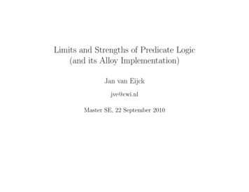
imposed on carbon fuels, SRs would be even more attractive than gas generators. Then, SRs inmicrogrids would play a pivotal role in reducing the carbon footprint at the local distribution level.However, it is particularly important to identify the most suitable use cases for early adoption and theright balance of generation mix with other clean technologies as SRs achieve a level of technologicaland financial maturity. Section 5 describes ongoing work to develop the comprehensive SR model in the XENDEE platformand adapt it for integrated energy system studies. As the next step, a model is being built that isspecifically designed for SR in microgrids in the XENDEE microgrid design and planning platform.The SR model will consider all datapoints described in the predecessor report. Section 6 provides the list of references. Appendix A provides an overview of the XENDEE optimization platform for technoeconomicassessment and portfolio optimization for future microgrids. The sample reports showing thecomprehensive financial and operational results for two different scenarios are provided asAppendices B and C.This report is a product of the Net-Zero Microgrid (NZM) Program at Idaho National Laboratorysupported by the Department of Energy, Office of Electricity Microgrid Program.2 The NZM Programrecognizes SRs as carbon-free energy sources for generation necessary for microgrids to transition awayfrom carbon fuel-based generation that is prevalent in today’s microgrids (see Figure ES-1).Figure ES-1. Net-zero generation.iv
ACKNOWLEDGMENTSWe thank Dan Ton, Program Manager for the DOE Office of ElectricityMicrogrid Program for supporting the effort that produced this report. Weappreciate the review and comments from John Jackson, National TechnicalDirector of the DOE Office of Nuclear Energy Microreactor Program, and DavidShropshire, INL Nuclear Economist. In addition, we appreciate the comments,conversations, and suggested edits from Juan Gallego-Calderon from INL’s Powerand Energy Systems.v
Page intentionally left blankvi
CONTENTS1.MICROGRIDS AND SMALL REACTORS . 12.THE PROXY MODEL . 23.CASE STUDY . 43.1System Overview . 43.23.1.1 Generation Options . 43.1.2 Electricity and Heating Demand . 53.1.3 Utility Tariff and Fuel Price . 63.1.4 Grid Exchange and Outage Models . 7The Scenarios . 73.3Scenario 1: Without Carbon Tax. 83.43.3.1 S1C0: Utility Purchase . 83.3.2 S1C1: With SR Flat Cost Model . 103.3.3 S1C2: With Economies of Scale . 13Scenario 2: With Carbon Tax . 144.3.4.1 S2C0: Utility Purchase . 143.4.2 S2C1: With SR Flat Cost Model . 143.4.3 S2C2: With Economies of Scale . 16DISCUSSION AND CONCLUSION . 185.PATH FORWARD TO THE SR MODEL . 206.REFERENCES. 22Appendix A Overview of XENDEE Platform . 24A-1. Introduction to XENDEE . 24A-2. XENDEE Portfolio Optimization. 24A-3. The Mathematical Modeling of XENDEE Optimization Engine. 26Appendix B Operational and Financial Results for S2C2 . 29Appendix C Operational and Financial Results with Investment Cost Model . 45vii
FIGURESFigure ES-1. Net-zero generation. . ivFigure 1. Small reactor parameters for technoeconomic studies identified in the earlier report.1 . 3Figure 2. Parameters estimates used for the proxy model. . 4Figure 3. XENDEE single-node GIS microgrid model with potential generator options. 4Figure 4. Time-series profile for solar PV performance data. . 5Figure 5. Time-series profile for electrical load (shows peak day each month). . 6Figure 6. Time-series profile for water-heating load (shows peak day each month) . 6Figure 7. Hourly marginal CO2 emission of CAISO in 2018. . 7Figure 8. Small reactor’s economies of scale in purchase price (EOS model) 1. . 8Figure 9. Technoeconomic analysis result summary for S1C0. 9Figure 10. Technoeconomic analysis result summary for S1C1. 11Figure 11. Monthly breakdown of microgrid cost for S1C1 and comparison to S1C0. . 12Figure 12. Time-series dispatch for the microgrid assets for January 1 for S1C1 . 12Figure 13. Monthly breakdown of microgrid cost for S1C2 and comparison to S1C0. . 13Figure 14. Time-series electricity dispatch in microgrid on January 1 for S1C2. . 13Figure 15. Monthly breakdown of microgrid costs for S2C0. . 14Figure 16. Monthly breakdown of electricity and fuel imports for S2C1. . 15Figure 17. Monthly breakdown of microgrid cost for S2C1 and comparison to S2C0. . 15Figure 18. Time-series electricity dispatch in microgrid on January 1 for S2C1. . 16Figure 19. Time-series electricity dispatch in microgrid on January 4 for S2C1. . 16Figure 20. Monthly breakdown of microgrid cost for S2C2 and comparison with S2C0. . 17Figure 21. Time-series electricity dispatch of microgrid for January 1 for S2C2. . 17Figure 22. Plugin for producing and importing SR catalog in XENDEE. . 21Figure A-1. Energy flows in the XENDEE optimization engine. . 25Figure A-2. The workflow of XENDEE optimization engine. . 26Figure A-3. Several constraints modeled in the XENDEE optimization engine. . 27TABLESTable 1. Technoeconomic modeling parameters for other generation technologies considered inmicrogrid. . 5Table 2. Comparison of optimization results with different microgrid scenarios and cases. 19viii
Page intentionally left blankix
ACRONYMSBESbattery energy storageCAISOCalifornia Independent System OperatorCHPcombined heat and powerDoDU.S. Department of DefenseDOEU.S. Department of EnergyEOSeconomies of scaleHALEUhigh-assay low enriched uraniumIAEAInternational Atomic Energy AgencyINLIdaho National LaboratoryLCOElevelized cost of electricityMARVEL Microreactor Applications Research Validation and EvaLuationMMRMicro Modular ReactorNGGnatural gas generatorNPPnuclear power plantNRELNational Renewable Energy LaboratoryNZMNet-Zero MicrogridO&Moperations and maintenanceOPGOntario Power GenerationPVphotovoltaicSCESouthern California EdisonSCOStrategic Capabilities OfficeSMRsmall modular reactorsSOCstate-of-chargeSRsmall reactorsTOUtime of utilizationTREATTransient Reactor TestTRISOtristructural isotropicUSNCUltra Safe Nuclear Corporationx
Page intentionally left blankxi
Net-Zero Microgrid Program Project Report:Small Reactors in Microgrids1.MICROGRIDS AND SMALL REACTORSA microgrid is defined by IEEE 2030.7 TM-2017, “IEEE Standard for Specification of MicrogridControllers,” as:A group of interconnected loads and distributed energy resources with clearlydefined electrical boundaries that act as a single controllable entity with respectto the grid and can connect and disconnect from the grid to enable it to operatein both grid-connected and island modes.3Microgrids are considered foremost for their value for resiliency in times of extreme weather eventsor other natural or human-caused calamities. Scientific evidence shows that these events arising fromglobal warming are becoming more common and adversely impacting the resiliency and integrity ofelectrical grids.4 The rapid shift towards clean but variable generation technologies, such as wind andsolar photovoltaics (PVs), will affect the resilience of the electrical grid due to the increased generationuncertainty and intermittency and reduction of spinning inertia from retired fossil-based synchronousgeneration.In addition to their use in communities and industries in remote areas that are isolated from or weaklyconnected to the central grid structure, microgrids are increasingly considered an integral componentwithin the electrical grid structure. The grid connection allows the two-way exchange of power providingthe flexibility of generation sizing within microgrids. Microgrids can decentralize larger grids into smallerentities, each capable of sustaining themselves without supply from the grid by aggregating localdistributed resources and with support from energy-storage technologies. Depending upon the availabilityof reliable generation sources, microgrids can be made immune to grid loss arising from the loss of weaktransmission infrastructure or due to extreme weather events. While microgrids are increasingly adoptedby commercial and industrial facilities and military bases irrespective of grid-connection availability,their eventual adoption in future applications, such as charging plazas and extraterrestrial stations, iswidely accepted. The scale of microgrids can vary widely by application depending on the criticalfunctions to be supported when islanding is required and the investment in generation assets made bymicrogrid owners/operators to support those critical functions and/or to supply power and energy or otherservices to the connected utility. Applications targeted in this project range from hundreds of kilowatts totens of megawatts; however, no hard lower and upper limits are set by the definition of a microgrid.Currently, distributed wind and solar PV generators are central to microgrid architecture due to their costeffectiveness and scalability, but their operation as non-dispatchable generation and their intrinsicvariability mean that there is a need for a scalable and reliable clean generation to complement theirshortcomings for sustainable microgrids.The use of small modular reactors (SMRs) and microreactors, collectively referred to as smallreactors (SRs) in this report, in microgrids has received significant research interest due to their smallersize, compact and long-lasting fuel, ease of transportation and assembly, flexible siting, improved safetyfeatures, and improved flexible-operation capabilities.5 The SR generations that would be of interest tothe scale microgrids referenced in this report range from 100 kW to 20 MW that would be encompassedby reactors referred to as microreactors and SMRs. For microgrid applications, SRs designs that aremanufactured in a factory setting and can be transported in a commission-ready form to the microgrid bytruck, rail, or air transportation are of most interest. SRs are typically designed with long-lasting fuels.Once loaded, the reactor fuel can last from 5 to 30 years.6 This is a major advantage of SRs over dieselgenerators, which, apart from their large carbon emissions, face difficulties in fuel transportation duringextreme weather events. SRs are designed to be inherently safe and accident-tolerant due to features, such1
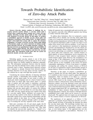
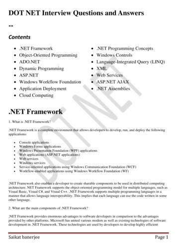
as simpler integral designs, passive coolant circulation, containment, shutdown systems, andunderwater/underground configurations.7 Further, the potential of SRs to provide heat along withelectricity enhances their economic potential and adds value to flexible-operation capability, adding moreimpetus towards achieving carbon-reduction goals.SRs are being developed in all major technological lines of reactors, including water-cooled reactors,high-temperature gas-cooled reactors, fast-neutron reactors, and molten-salt reactors.5 The MicroreactorApplications Research Validation and Evaluation (MARVEL) microreactor project, supported by the U.S.Department of Energy, will be one of the first SRs in the U.S. and will be developed at Idaho NationalLaboratory (INL) and installed at the Transient Reactor Test Facility (TREAT) by late 2023. MARVEL isa 100-kWt fission reactor that will enable the testing of several new non-traditional nuclear microgridapplications.8 Under Project Pele, the Department of Defense’s Strategic Capabilities Office (SCO) isbuilding a mobile microreactor technology with a prototype set to be demonstrated at INL by 2024.9 Thetristructural isotropic (TRISO) fuel makes Pele reactors inherently safe and resilient against externalattacks without needing large evacuation zones. Pele reactors will be sized between 1 to 5 MW, use highassay low enriched uranium (HALEU), and can be transported by trucks, rails, and ships. The MicroModular Reactor (MMR) is another SR project in Canada, which will be hosted at the Chalk RiverLaboratory site. It is a joint venture between the Ultra Safe Nuclear Corporation (USNC) and OntarioPower Generation (OPG) that aims to host an SR plant by 2026. Several other SR technologies are underdevelopment and are expected to start operation by the late 2020s for demonstration purposes.8,10-12 Forpractical use in microgrids in the first few years of production, SRs will need financial incentives tocompete with other clean-energy generation.10 As the technology matures and moves into factoryproduction, SRs are expected to become economically competitive with other sources of clean generation.SRs can work with other forms of clean generation to develop sustainable energy microgrids.2.THE PROXY MODELSR introduce a significant shift in the energy market and the deployment model traditionally adoptedby the nuclear industry. The initial deployments of SRs are expected to be more towards the marketsvaluing resilience, energy equity, and environmental justice and less constrained by the differential costfor technology learning. Some of these initial potential use cases identified in the literature includemilitary bases, isolated communities, urban applications, and disaster relief. SRs have the potential toexpand to the emerging energy market in Eastern Europe and Asia in the mid-term and support urbanmarkets and megacities and electrical grids in the longer term.13 Although losing the economy withdrastically reduced size from older NPP designs, SRs can recover their costs by offsetting gains fromsimplified designs, standardized modules, increased learning rates, reduced construction schedule, andfactory production. Efforts have been made to represent the cost characteristics of SRs with specificdesigns modifying the traditional top-down and bottom-up cost estimation techniques used for olderNPPs.10,14 This report utilizes the generic set of parameters identified in the predecessor report1 tocharacterize SRs for technoeconomic studies.Before developing the SR model, a proxy model was created in the XENDEE platform by changingthe parameters of the existing gas-generator model in a way that reflects the behavior of SRs. Theobjective is to examine XENDEE’s adaptability to include SRs in technoeconomic feasibility analysis andobtain initial optimization results for SR in microgrids. Appendix A provides an overview of theXENDEE platform and its functional capabilities for technoeconomic analysis and portfolio optimizationof microgrids. The technoeconomic characteristics that are common to the XENDEE’s gas-generatormodel are translated into the proxy model. The parameters that are applicable only to SRs are yet to beadded. Figure 1 shows the technoeconomic datapoints explored in the earlier report1 and highlights theones used in the proxy model.2
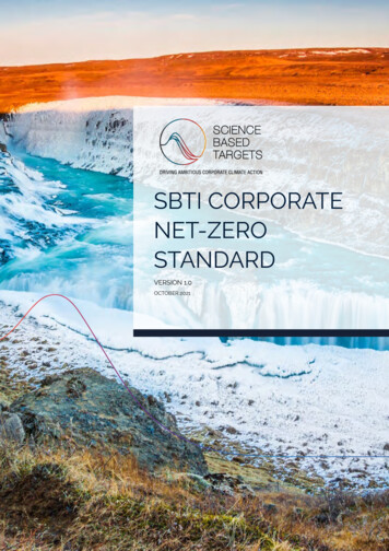
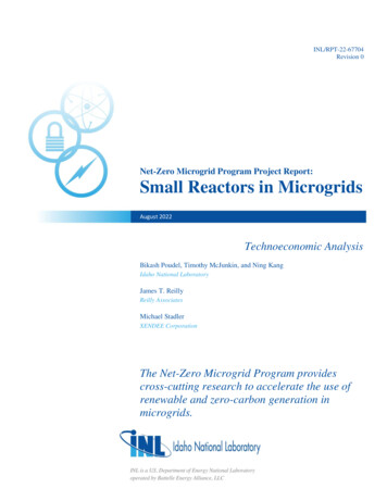
Owner sCostFront-endInterest DuringConstructionFuel CostBack-endNon-fuel CostsHeat toPower RatioMinimumUp TimeEfficiency/PerformanceMinimumDown TimeOperation andMaintenanceCostManeuveringCycle LimitsSR Technoeconomic CostPowerChangeLimitsRamp RateLimitsPlant LifeParametersFuel LifeReactor LifeFigure 1. Small reactor parameters for technoeconomic studies identified in the earlier report.1The purchase cost is an area where SRs differ significantly from gas generators. A significant portionof SR’s investment cost goes for the plant installation including land rights and site utilities, building andstructures, engineering and design, and construction services.1 The installation cost calculated for SR in theearlier report1 is used as the purchase cost of the plant. The economies of scale in the sizing of SR are drivenby cost reduction due to factory-produced units and/or co-location of multiple modules at the same site. Itwill result in a reduced relative installation cost ( /MW) as the plant size increases.The fuel cost for the gas generator is calculated based on the utilization (i.e., cumulated output inkWh) with the choice fuel and the corresponding price rate. The fuel in the gas-generator model couldeither be biogas or natural gas. In SRs, the fuel lasts for several years before it needs refueling. Tosimplify, the front- and back-end fuel costs are calculated and annualized over the refueling period torepresent them as a part of annual operations and maintenance (O&M) costs. Alternatively, the uraniumfuel supply and cost can be manually calculated and translated into the biogas or natural-gas fuel cost forthe proxy representation. For the proxy model, the variable O&M cost calculated in the earlier report1 willbe used to represent both fuel and non-fuel costs. Since the gas-generator model needs the specificationfor the choice of fuel, biogas was selected with a supply price of 0 /kg because the fuel cost is alreadyconsidered in the O&M cost.SRs can be operated in combined heat and power (CHP) mode to supply both heat and electricity.This could be done in two different ways: either by extracting process steam or by using the unused heatfrom the turbine exhaust. The process steam is extracted when high-quality heat is needed (e.g., hightemperature electrolysis). For low-temperature heat applications, such as district heating, the heatavailable at turbine exhaust can be used. XENDEE considers the latter form of the CHP operationutilizing the heat at the turbine exhausta. For the proxy model, it is assumed that the SR can providemaximum CHP capability with all remaining heat at turbine exhaust available for low-temperatureheating applications. For 33.33% thermal efficiency, the maximum possible heat to power ratio would be2:1. The rest of the datapoints are minimum up and down times, minimum loading, and the plant lifetaken as 12 hours, 20%, and 50 years respectively, as shown in Figure 2.aA new feature would be required in XENDEE to account for SR’s high-grade heat applications for industrial processes orhigh temperature electrolysis.3
11,233,100 /MWInstallation cost(Based on 1 MW unit)20%Minimum LoadingParameters50 yPlant Life0.0545 /kWhVariable O&M Cost12 hMinimum Up/DownTime1.67%Fuel Input(Electric Efficiency)2:1Heat to Power RatioFigure 2. Parameters estimates used for the proxy model.3.3.13.1.1CASE STUDYSystem OverviewGeneration OptionsThe SR, represented by the proxy model for this case study, is considered a generation option for amicrogrid developed on a 15-MW electric peak military site in southern California, which has a peak hotwater/heating load of 1800 kWh. Other generator options include solar PV, electric storage, boilers, andnatural gas generator (NGG)b. The XENDEE optimization tool uses mixed-integer linear programming toevaluate the optimum types, numbers, and sizes of generators to meet the microgrid demand with variousobjectives (e.g., cost minimization, CO2 minimization). Figure 3 shows a single-node XENDEEmicrogrid setup showing different generation options for the proposed microgrid. The technoeconomicparameters for all potential generation assets in the microgrid are listed in Table 1.Figure 3. XENDEE single-node GIS microgrid model with potential generator options.bThis case study can be implemented effectively with the proxy model because it uses only low-grade heat that is part of theexisting XENDEE platform.4
Table 1. Technoeconomic modeling parameters for other generation technologies considered inmicrogrid.GenerationTechnologyTechnoeconomic ParametersPVPV panel cost 1700 /kWDC, Lifetime 30 y;Inverter cost 200 /kWDC, Lifetime 15 y, Power factor 100%;System losses 14%, Inverter eff 96%, Panel eff 10%, PV tilt 34⁰ S;Panel technology Thin-film, Array type Fixed ground-mounted;Maximum install space 274278 ft2Electric StorageEnergy module cost 550 /kWh, Inverter cost 196/ kW, O&M cost 0.333 /kWh/moModule size 600 kWh, System Life 18 yCharging Eff Discharging Eff 87%, Power factor 100%, Max SOC 100%, Min SOC 5%.Natural-GasUnit size 1 MW, Nameplate efficiency 26%, Heat to power ratio 1.56,GeneratorCHP mode ONPurchase price 2.9 M/unit, Lifetime 15 years, O&M (variable) 0.0024 /kWh/y, O&M (fixed) 0.0185 /kW/y,Fuel price 0.5716 /Therm, CO2 emission factor 0.1808 kgCO2/kWhThe PV performance data is calculated based on the location of the microgrid to generate an hourlytime-series profile shown in Figure 4. The performance data represents the fraction of the installedelectrical power capacity that a PV plant can generate each hour. In addition to the time-series irradianceprofile, the panel technology type (standard, premium, or thin-film), array type (fixed or tr
Net-Zero Microgrid Program Project Report: Small Reactors in Microgrids August 2022 Technoeconomic Analysis Bikash Poudel, Timothy McJunkin, and Ning Kang . workflow of the XENDEE optimization engine from inputs to outputs together with objectives is shown in Figure A-2. 26 Figure A-2. The workflow of XENDEE optimization engine.