Transcription
INSTRUCTION MANUALFORVOLTAGE REGULATORModel: SR4A & SR8APart Number: 9 0177 00 XXXPublication Number: 9 0177 00 990Revision: R09/97CALL US TODAY1-888-POWER-58REQUEST A QUOTEparts@genpowerusa.comSHOP ONLINEwww.genpowerusa.com
INTRODUCTIONThis manual provides information concerning the operation and installation of a SR4A & SR8A VoltageRegulator. To accomplish this, the following is provided. Specifications Functional Description Installation Information Operation MaintenanceWARNINGTO AVOID PERSONAL INJURY OR EQUIPMENT DAMAGE, ONLYQUALIFIED PERSONNEL SHOULD PERFORM THE PROCEDURESPRESENTED IN THIS MANUAL.WARNINGAll SR4A and SR8A Voltage Regulators are shipped factory presetfor 120 Vac sensing.REVLMNPRECA1560915959160571619516334iCALL US TODAY1-888-POWER-58REQUEST A QUOTEparts@genpowerusa.comSHOP ONLINEwww.genpowerusa.com
First Printing: August 1971Printed in USA 1997, Basler Electric Co., Highland, IL 62249September 1997CONFIDENTIAL INFORMATIONOF BASLER ELECTRIC COMPANY, HIGHLAND, IL. IT IS LOANEDFOR CONFIDENTIAL USE, SUBJECT TO RETURN ON REQUEST,AND WITH THE MUTUAL UNDERSTANDING THAT IT WILL NOT BEUSED IN ANY MANNER DETRIMENTAL TO THE INTEREST OFBASLER ELECTRIC COMPANY.It is not the intention of this manual to cover all details and variations in equipment,nor does this manual provide data for every possible contingency regardinginstallation or operation. The availability and design of all features and options aresubject to modification without notice. Should further information be required,contact Basler Electric Company, Highland, Illinois.BASLER ELECTRIC, BOX 269PHONE 618-654-2341HIGHLAND, IL 62249 USAFAX 618-654-2351iiCALL US TODAY1-888-POWER-58REQUEST A QUOTEparts@genpowerusa.comSHOP ONLINEwww.genpowerusa.com
CONTENTSSECTION 1.0GENERAL INFORMATION. 1-11.11.2Description. 1-1Specifications. 1-1Electrical Specifications . 1-1Physical Specifications . 1-2Optional Features . 1-2Accessories . 1-3Model Number Description and Selection . 1-3Typical Model Number . 1-4Model Number Designations. 1-41.31.41.5SECTION 2.0PRINCIPLES OF OPERATION. 2-12.12.22.3Functional Circuits . 2-1Overall Block Diagram . 2-1Application Information . 2-1Parallel Compensation. 2-2SECTION 3.0INSTALLATION. 3-13.1Mounting . 3-1Outline Drawing . 3-1Interconnection . 3-2Voltage Adjust Potentiometer P/N (03456) . 3-2Paralleling Potentiometer P/N (03469) . 3-2Brush Type Rotary Exciter Interconnection . 3-5Brushless Type Rotary Exciter (or Static Exciter)Interconnection . 3-6Parallel Compensation. 3-6Reactive Droop Compensation (Droop). 3-7Reactive Droop Compensation (Cross-Current). 3-7Reactive Differential (Cross-Current) Compensation CTInterconnection . 3-8Top View of Voltage Regulator . 3-83.23.33.43.5SECTION 4.0OPERATION. 4-14.14.24.34.44.54.64.74.8General . 4-1Operation at Reduced Speeds . 4-1Voltage Shutdown. 4-1Adjustments . 4-2Wiring . 4-2Initial Operation. 4-2Field Flashing. 4-4Parallel Operation . 4-4SECTION 5.0MAINTENANCE, REPLACEMENT PARTS ANDTROUBLESHOOTING . 5-15.15.2Preventive Maintenance . 5-1Corrective Maintenance. 5-1Operational Test . 5-1Replacement Parts . 5-2Component Location and Identification. 5-2SR4A Replacement Parts . 5-35.3iiiCALL US TODAY1-888-POWER-58REQUEST A QUOTEparts@genpowerusa.comSHOP ONLINEwww.genpowerusa.com
CONTENTS - ContinuedSECTION 55.45.5MAINTENANCE, REPLACEMENT PARTS, ANDTROUBLESHOOTING - ContinuedSR8A Replacement Parts .5-3Wiring Diagram.5-4Warranty and Repair Service .5-5Troubleshooting.5-5Troubleshooting Chart .5-6ivCALL US TODAY1-888-POWER-58REQUEST A QUOTEparts@genpowerusa.comSHOP ONLINEwww.genpowerusa.com
SECTION 1GENERAL INFORMATION1-1. DESCRIPTIONa. The SR4A and SR8A Voltage Regulators precisely control the output voltage of an ac electricgenerating system by controlling the amount of current supplied to the exciter (or generator) field.This includes brushless rotary exciters, brush type rotary exciters or direct excitation into thegenerator field of machines within the regulator's power rating.b. The regulators consist of silicon controlled rectifiers (SCR's) transistors, transformers, silicondiodes, resistors and capacitors. The voltage regulators contain no electrolytic capacitors and arerelatively unaffected by temperature, humidity, vibration and shock.1-2. SPECIFICATIONSTable 1-1 provides the electrical specifications of the SR4A and SR8A while Table 1-2 provides thephysical specifications.Table 1-1. Electrical Specifications.Input Power:SR4A:SR8A:Output Power:SR4A:SR8A:Input Sensing:SR4A:SR8A:95 - 139 Vac ( 10), 50/60 Hz, 840 VA.190 - 277 Vac ( 10), 50/60 Hz, 1680 VA.63 Vdc @ 7 A Maximum Continuous, 90 Vdc @ 10 A One MinuteForcing.125 Vdc @ 7 A Maximum Continuous, 180 Vdc @ 10 A OneMinute Forcing.NEMA Standard 60 Hz: 100 - 110/190 - 200 - 208/220 - 230 240/380 - 400 - 415/500 Vac; 10%.NEMA Standard 60 Hz: 120 - 139/208/240/416/480/600 Vac; 10%.Input Sensing Burden:SR4A:SR8A:10 VA.10 VA.Parallel Compensation:5 A Input; 25 VA Burden. Droop adjust to 6%.Minimum Field Resistance:SR4A:SR8A:9Ω18 ΩVoltage Regulation: 1/2% (Average voltage).1-1CALL US TODAY1-888-POWER-58REQUEST A QUOTEparts@genpowerusa.comSHOP ONLINEwww.genpowerusa.com
Table 1-1. Electrical Specifications (con’t).Response Time: 17 mS on 60 Hz systems; 20 mS on 50 Hz systems.Voltage Adjust Range: 10% on nominal.Power Dissipation (Max):60 WattsTemperature Coefficient: 1/2% for a 40 C (104 F) change.Table 1-2. Physical Specifications.Operating TemperatureRange:-55 C (-67 F) to 70 C ( 158 F).Storage TemperatureRange:-65 C (-85 F) to 100 C ( 212 F).Vibration:Tested to withstand 5 G's from 20 to 260 Hz.Mounting:Designed for operation when mounted directly to an enginegenerator set. It is strongly recommended that the voltageregulator be mounted vertically for optimum cooling.Overall Dimensions:Height:Width:Depth:11.5 inches (292 mm).8.38 inches (213 mm).5.0 inches (127 mm).Weight:13 lbs. (5.8 kg.).1-3. OPTIONAL FEATURESThe internal voltage regulator optional features listed below are designated by a combination ofletters and numbers in the complete model number. (See Table 1-3 and/or contact the factory foradditional variations).a. Parallel compensationc. Voltage build up relayb. Single or three-phase sensing.d. Sensing Voltagee. Coverf. Voltage adjust rheostatg. Type of stability circuit1-2CALL US TODAY1-888-POWER-58REQUEST A QUOTEparts@genpowerusa.comSHOP ONLINEwww.genpowerusa.com
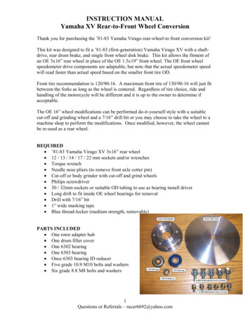
1-4. ACCESSORIESa. The following is a partial list of accessories that are available for use with the SR4A and SR8AVoltage (13)(14)(15)(16)(17)Underfrequency protection.Excitation support systems.EMI suppression filters.Low and medium voltage power isolation transformers.Paralleling current transformers.Manual Voltage control modules.Volts per hertz sensing modules.DC sensing modules.400 hertz regulator.Voltage regulators operating from 60 hertz power on 400 hertz generatorsWide range voltage adjust circuit components.VAR/Power Factor Controller.Overvoltage protection.Control switches.Motor operated controls.Line drop compensators.Voltage transient suppression filters.b. Information covering these accessories may be obtained by consulting the applicable instructionmanual and product bulletin, or by contacting your nearest Basler Electric Sales Representative orthe factory.c. An external voltage adjust rheostat may be obtained from a source other than Basler Electric.This rheostat must be a minimum of 2 watts in size. The nominal required resistance is 175 ohms.Although any value from 150 ohms to 250 ohms may be used, a slight change in the voltage adjustrange will occur.1-5. MODEL NUMBER DESCRIPTION AND SELECTIONThe model number of the voltage regulator is a combination of letters and numbers indicating thefeatures which are included in the regulator. An example of a model number, showing the manner inwhich the various features are designated, is shown in Figure 1-1. A complete list of variousfeatures and their description is given in Table 1-3.1-3CALL US TODAY1-888-POWER-58REQUEST A QUOTEparts@genpowerusa.comSHOP ONLINEwww.genpowerusa.com
SR4A2B15B3EMODEL AND POWER RATINGPARALLEL PROVISIONSVOLTAGE BUILD-UP PROVISIONSSINGLE-PHASE SENSINGENCLOSURETYPE OF VOLTAGE ADJUSTMENTTYPE OF STABILITY CIRCUITD2556-0602-20-97Figure 1-1. Typical Model Number.Table 1-3. Model Number Designations.Sample Model ions withadjustableslide sesensing.16-Selectable3-phasesensing atsuppliedseparatelywithregulator.AA-For use onall brush-typeand mostbrushlessexciters ongeneratorsrated over150 kW.E-For usewithbrushlessexciters(primarily ongeneratorsrated 150 kWor less) orwith all rotaryexciters.The above style chart represents our standard product offering.1-4CALL US TODAY1-888-POWER-58REQUEST A QUOTEparts@genpowerusa.comSHOP ONLINEwww.genpowerusa.com
The following styles are available on a special order basis.Sample Model NumberSR8ASR4SR8AA-Surfacemounted.31-No bleslide wireresistor.B15A-No relay.B-Build-uprelay.CHermeticallysealed relay.15Selectable 1phasesensing.16Selectable 3phasesensing w/Fastonconnectors.3-Parallelprovisionswith eostatinternallyinstalledwith lockingshaft.EA-For useon all brushtype andmostbrushlessexciters ongeneratorsrated over150 kW.B-For useasstaticexciter.E-For usewithbrushlessexciters(primarily ongeneratorsrated150kW or less)or with allrotaryexciters.1-5CALL US TODAY1-888-POWER-58REQUEST A QUOTEparts@genpowerusa.comSHOP ONLINEwww.genpowerusa.com
SECTION 2PRINCIPLES OF OPERATION2-1. FUNCTIONAL CIRCUITSRefer to the Block Diagram, Figure 2-1. The voltage regulator senses the generator voltage, compares a rectified sample of that voltage with a reference diode (zener) voltage and supplies the fieldcurrent required to maintain the predetermined ratio between the generator voltage and thereference voltage. This unit consists of five basic circuits. These are a sensing circuit, an errordetector
generator set. It is strongly recommended that the voltage regulator be mounted vertically for optimum cooling. Overall Dimensions: Height: Width: Depth: 11.5 inches (292 mm). 8.38 inches (213 mm). 5.0 inches (127 mm). Weight: 13 lbs. (5.8 kg.). The internal voltage regulator optional features listed below are designated by a combination of letters and numbers in the complete model number .