Transcription
F11c INSTRUCTION MANUALWe’ll Make It Stress-FreeIf you have any questions along the way, just give us a call.1-888-333-9952. We’re ready to help!Scan for easy install videosan.us/251
IMPORTANT SAFETY INSTRUCTIONS – SAVE THESE INSTRUCTIONS – PLEASE READ ENTIRE MANUAL PRIOR TO USEBefore getting started, let’s make sure this mount is perfect for you!1Does your TV weigh more than 35 lb (15.9 kg) including accessories?35 lb(15.9 kg)2No — Perfect!Yes — This mount is NOT compatible. Visit vuepoint.sanus.com or call 1-888-333-9952 to find a compatible mount.What is your wall made of?Drywall withwood studs3Perfect!Solid concrete or concreteblock - call 1-888-333-9952Do you have all of the tools needed?Unsure? Call 1-888-333-9952Optional1/8 in.(3 mm)Wood4?7/16 in.(12 mm)3/8 in.(10 mm)3/8 in.(10 mm)ConcreteReady to begin?Please read through these instructions completely to be sure you’re comfortable with this easy install process. Also check your TVowner’s manual to see if there are any special requirements for mounting your TV.If you do not understand these instructions or have doubts about the safety of the installation, assembly or use of this product, contactCustomer Service at 1-888-333-9952.CAUTION: Avoid potential personal injuries and property damage!2 This product is designed for use in wood stud, solid concrete, and concrete block walls - DO NOT install into drywall aloneThe wall must be capable of supporting five times the weight of the TV and mount combinedDo not use this product for any purpose not explicitly specified by manufacturerManufacturer is not responsible for damage or injury caused by incorrect assembly or use
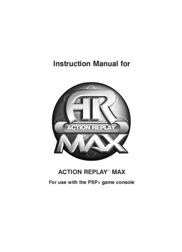
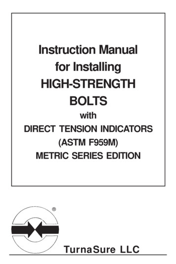
Dimensions7.9[20.0]in.[cm]3.9[10.0]3.0[7.5]12 8.9[22.6]12 6]9.1[23.1]1.7[4.3]3
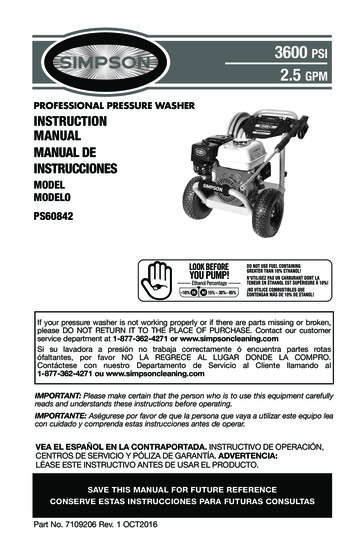
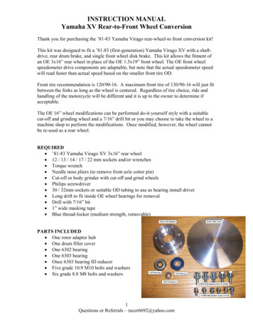
Supplied Parts and HardwareWARNING: This product contains small items that could be a choking hazard if swallowed.Before starting assembly, verify all parts are included and undamaged. If any parts are missing or damaged, do not return the damaged item toyour dealer; contact Customer Service. Never use damaged parts!NOTE: Not all hardware included will be used.STEP 1 Parts and HardwareTV Screws, Washers, and SpacersTV Bracket Extenders*M4 x 12mmM4 x 35mm05 x406 x4TV Bracket02 x2*Only needed for TVswith 20.0 x 20.0 cm(7 7 8 x 7 7 8 in.) holepatterns01 x1M6 ExtensionBracket Screws*M6 x 12mm03 x44M5 x 12mmM5 x 35mm07 x408 x4M6 x 12mmM6 x 35mm09 x410 x4M6 Nuts*††Nylon locking bracket nutsare poly-locks and will need tobe forcibly tightened.M604 x4M4/M511 x4M612 x413 x4
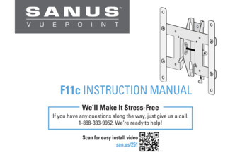
Concrete Installation Kit CMK2 (not included)STEP 2 Parts and HardwareWall Plate TemplateWall PlateContact Customer Service at 1-888-333-9952 to have theseadditional pieces shipped directly to you.1/4 x 2½ in.x21/4 in.x214 x115 x1Lag BoltsFischer UX 10 x 60 Anchorx21/4 x 2½ in.16 x25
STEP 1 Attach TV Bracket to TV1-1 Measure Your TV Hole PatternMeasure the width and height of your TV hole pattern in cm.Record your measurements:Width cm x Height cm75 mm 7.5 cm 3 in.100 mm 10 cm 4 in.200 mm 20 cm 7 7/8 in.inch dimensions are approximateesinchcm6
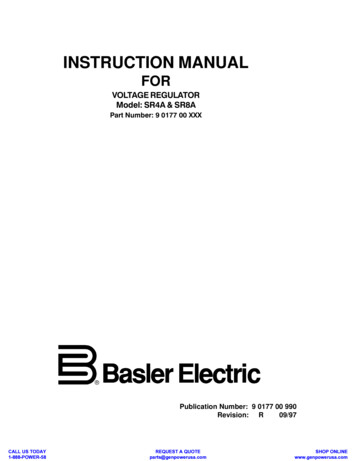
1-2 Assemble Your TV BracketB20.0 x 20.0Determine which TV bracket configuration to use, A or B basedon your TV hole pattern measurements.A20.020.07.5 x 7.510.0 x 10.020.0 X 10.010.07.50110.00220.0027.5020201030404These smaller hole patterns only use TV bracket 01 .Do not use the two TV bracket extenders 02 and four screws 03and four nuts 04 .3/8 in.(10 mm)wrench0303NOTE: Nuts04 are poly-locksand will need to beforcibly tightened.Assemble TV bracket extenders 02 onto TV bracket 01 as illustrated.Secure using four screws 03 and four nuts* 04 in the corner holesshown.7
1-3 Select TV Screw Diameter1-4 Select TV Screw LengthHand thread screws into the threaded insertson the back of your TV to determine whichscrew diameter (M4, M5, or M6) to use.If your TV has a flat back AND you want your TV closer to thewall, use the shorter screws.M4M5M6Spacers and longer screws are supplied to accommodate: Round/irregular back TVs TVs with inset mounting holes Extra space needed for cablesFLAT BACKROUND BACKINSET HOLESCABLESStandard configurationsare shown. For specialapplications, or if youare uncertain about yourhardware selection,contact Customer Serviceat 1-888-333-9952.CAUTION:Verify adequate threadengagment with the screw orscrew/spacer combination.- Too short will not hold the TV.- Too long will damage the TV.Too ShortCorrectToo Long8
1-5 Attach TV BracketPosition your TV bracket configuration over your TV hole pattern - making sure the brackets are vertically centered and level.Install using either the short screw and washer or spacer, long screw and washer combination you selected for your TV.IMPORTANT: Ensure TV bracket is securely fastened before moving on to the next step.Short screw and washer0205 07 0901TV BracketConfiguration BIllustrated(with spacers)11 12Spacer, long screw and washer0201TV BracketConfiguration AIllustrated(with spacers)06 08 101311 129
STEP 2A Attach Wall Plate - Wood StudCAUTION: Avoid potential personal injuries and property damage! Drywall covering the wall must not exceed 5/8 in. (16 mm)Minimum wood stud size: common 2 x 4 in. (51 x 102 mm) nominal 1½ x 3½ in. (38 x 89 mm)1.Locate your stud. Verify and mark the center of the stud by finding the stud edges using an awl, a thin nail, or an edge to edge stud finder.2.Position the wall plate template 14 at your desired height and line up the holes with your stud center line. Level the template and tape in place.3.Drill pilot holes using a 1/8 in. (3 mm) diameter drill bit. Remove wall plate template 14 .2½ in.(63.5 mm)IMPORTANT: Be sure to drill into the center of the stud.IMPORTANT: Pilot holes must be drilled to a depth of 2½ in. (63.5 mm).1 5/8 in.(16 mm)2314101/8 in.(3 mm)14
Install wall plate 15 using two lag bolts 16 . Tighten the lag bolts only until they are pulled firmly against the wall plate.4.CAUTION: Improper use could reduce the holding power of the lag bolt. DO NOT over-tighten the lag bolts16 .NOTE: If needed, you can make small level adjustments to the wall plate by loosening the bottom lag bolt and shifting the wall plate until level.Tighten the bottom lag bolt 16 when adjustments are complete.41516151611
STEP 2B Attach Wall Plate - Solid Concrete / Concrete BlockCAUTION: Avoid potential personal injuries and property damage!Concrete Installation Kit CMK2 is not included Mount the wall plate 15 directly onto the concrete surfaceMinimum solid concrete thickness: 8 in. (203 mm)Minimum concrete block size: 8 x 8 x 16 in. (203 x 203 x 406 mm)1.2.Position the wall plate template 14 on the wall at your desired height. Level the wall plate template and mark the hole locations.Drill two pilot holes using a 3/8 in. (10 mm) diameter masonry drill bit.(see page 5) Contact Customer Serviceat 1-888-333-9952 to have the additionalhardware shipped directly to you.IMPORTANT: Pilot holes must be drilled to a depth of 3 in. (75 mm). Never drill into the mortar between blocks.123 in.(75 mm)3/8 in.(10 mm)141412
3.Remove the wall plate template 14 and insert two anchors (Fischer UX 10 x 60 - included in the Concrete Installation Kit CMK2*).CAUTION: Be sure the anchors are seated flush with the concrete surface.4.Install wall plate 15 using two lag bolts 16 . Tighten the lag bolts only until they are pulled firmly against the wall plate.CAUTION: Improper use could reduce the holding power of the lag bolt. DO NOT over-tighten the lag bolts16 .*Contact Customer Service at 1-888-333-9952 to have the Concrete Installation Kit CMK2 shipped directly to you.NOTE: If needed, you can make small level adjustments to the wall plate by loosening the bottom lag bolt 16 and shifting the wall plate until level.Tighten the bottom lag bolt 16 when adjustments are complete (see page 11).3416*1513
STEP 3 Hang TV onto Wall PlateHEAVY! You may needassistance with this step.IMPORTANT: The locking tab needs to be in the unlockedposition before attaching the TV to the wall plate.Once the TV is on the wall plate, the locking tab needs to bein the locked position.14
TV AdjustmentsADJUSTING THE TILT: Loosen the knob on the TV bracket to adjustthe tilt of your TV. Tighten the knob when your TV is set to thedesired tilt.REMOVING THE TV: Place the locking tab into the unlockedposition and lift the TV up and out away from the wall plate.010115
ESPAÑOLINSTRUCCIONES DE SEGURIDAD IMPORTANTES. CONSÉRVELAS. LEA TODO EL MANUAL ANTES DE UTILIZAR ESTE PRODUCTO.Antes de comenzar, verifiquemos que este soporte sea perfecto para usted.1¿Su televisor pesa más de 15.9 kg (35 libras), incluidos los accesorios?15.9 kg(35 lb)23No — ¡Perfecto!Sí — Este soporte NO es compatible. Visite Vuepoint.Sanus.com o llame al 1-888-333-9952 para encontrar un soporte compatible.¿De qué está hecha su pared?Tabiques de yesocon montantes demadera¡Perfecto!Hormigón sólido o bloquesde cemento - llame al1-888-333-9952¿Tiene todas las herramientas necesarias?Optional1/8''(3 mm)Madera4?¿No está seguro? Llame al 1-888-333-99527/16''(12 mm)3/8''(10 mm)3/8''(10 mm)Hormigón¿Listo para comenzar?Lea estas instrucciones en su totalidad para estar seguro de sentirse cómodo con este fácil proceso de instalación. Consulte también elmanual del usuario de su televisor para ver si existe algún requisito especial para instalar su televisor en la pared.Si no entiende las instrucciones o si tiene dudas acerca de la seguridad de la instalación, del ensamblado o del uso del producto,contáctese con el servicio de atención al cliente al 1-888-333-9952 .PRECAUCIÓN: Evite lesiones y daños materiales.16 Este producto está diseñado para ser instalado en paredes con montantes de madera. NO lo instale en una pared de yeso únicamente.La pared debe soportar cinco veces el peso del televisor y del soporte juntos.No utilice este producto para ningún otro propósito que no sea el explícitamente especificado por el fabricante.El fabricante no se responsabiliza por ningún daño o lesión resultante del montaje incorrecto o del uso indebido.
ESPAÑOLPiezas y accesorios suministradosADVERTENCIA: Este producto contiene piezas pequeñas que, si fuesen tragadas, podrían producir asfixia.Antes de iniciar el ensamblaje, compruebe que todas las piezas estén incluidas y en buenas condiciones. Si faltan piezas o alguna está dañada,no devuelva el artículo al distribuidor; póngase en contacto con el servicio de atención al cliente. Nunca utilice piezas deterioradas.NOTA: No todos los accesorios incluidos deberán utilizarse.PASO 1 Fijar la placa de sujeción al televisor1-1 Mida el patrón de orificios del televisor1-2 Arme la placa de sujeción del televisorMida en mm el ancho y el alto del patrón de orificios del televisor.Determine qué configuración de placa de sujeción debe usar (A o B)según las medidas del patrón de orificios del televisor.patrones de orificios más pequeños solo requieren placa deA Lossujeción 01 .No utilice las cuatro extensiones de la placa de sujeción 02 ni losocho tornillos 03 .Anote las medidas:Ancho cm x Alto cmBEnsamble las extensiones 02 de la placa de sujeción y la placa desujeción 01 tal como se muestra en la ilustración.Fije colocando ocho tornillos 03 en los orificios de las esquinas quese muestran en la imagen.17
ESPAÑOL1-3 Seleccione el diámetro de los 1-4 Seleccione el largo de los tornillostornillos para el televisorpara el televisorEnrosque manualmente los tornillos en losencastres roscados del dorso del televisor afin de determinar qué diámetro de tornillos(M4, M5, o M6) utilizar.Si el dorso del televisor es plano, utilice lostornillos cortos.PRECAUCIÓN:Verifique que el tornillo o la combinaciónde tornillo y espaciador enrosquenLos espaciadores y los tornillos largos secorrectamente.proporcionan para: televisores con dorso irregular o redondeado - Si el tornillo es demasiado corto, no televisores con orificios de montaje intercalados sostendrá el televisor. dejar un espacio adicional para cables- Si es demasiado largo, dañará el televisor.1-5 Fije la placa de sujeciónPosicione la placa de sujeción armada sobre el patrón de orificios del televisor y verifique que esté centrada y nivelada verticalmente.Instale las placas de sujeción usando la combinación que haya seleccionado para su televisor: tornillo corto y arandela o espaciador, o bientornillo largo y arandela.PASO 2A Fijar la placa mural - ÚNICAMENTE montantes de maderaPRECAUCIÓN: Evite lesiones y daños materiales. 1.2.3.18El yeso que recubre la pared no debe exceder los 16 mm (5/8'').Tamaño mínimo del montante de madera: común 51 mm x 102 mm (2'' x 4''); nominal 38 mm x 89 mm (1½'' x 3½'').Localice un montante. Busque los bordes del montante y marque el centro con un punzón o un clavo delgado, o bien utilice un detector debordes de montantes.Ubique la plantilla de placa mural 14 a la altura deseada y alinee los orificios con la línea central de los montantes. Nivele la plantilla y fíjelacon cinta adhesiva en el lugar.Con una mecha de 5.5 mm (7/32'') de diámetro, realice los orificios guía. Retire la plantilla de placa mural 14 .IMPORTANTE: Asegúrese de perforar el centro del montante.IMPORTANTE: Los orificios guía deben realizarse hasta una profundidad de 75 mm (3'').
ESPAÑOL4.Ajuste los tornillos tirafondo 16 solamente hasta que queden firmes contra la placa mural 15 .PRECAUCIÓN: El uso indebido podría reducir la capacidad de retención de los tornillos tirafondo. NO ajuste en exceso los tornillos tirafondo.PASO 2B Fijar la placa mural - Hormigón sólido o bloques de cemento 1.2.3.4.PRECAUCIÓN: Evite lesiones y daños materiales.El Kit de instalación en hormigón CMK2 noInstale el módulo de la placa mural 15 directamente sobre la superficie de hormigónestá incluido (Ver página 5) Comuníquesecon el servicio de atención al cliente al 1-888Espesor mínimo del hormigón: 8 pulgadas (203 mm)333-9952 para sol
15Mount the wall plate directly onto the concrete surface Minimum solid concrete thickness: 8 in. (203 mm) Minimum concrete block size: 8 x 8 x 16 in. (203 x 203 x 406 mm) 1. Position the wall plate template 14 on the wall at your desired height. Level the wall plate template and mark the hole locations. 2. Drill two pilot holes using a 3/8 in .