Transcription
InstructionBulletinBoletín SR12/0212/02Raleigh, NC, USAALTIVAR 11Adjustable Speed Drive Controllers Start-up GuideGuía de puesta en marcha de los variadores develocidad ajustableGuide de mise en service des variateurs de vitesseFRANÇAISESPAÑOLENGLISHRetain for future use.Conservar para uso futuro.À conserver pour usage ultérieur.
ALTIVAR 11 Start-up GuideSetting Up the ALTIVAR 11 Drive ControllerVVDED302031USR12/0212/02SETTING UP THE ALTIVAR 11 DRIVE CONTROLLERRead and follow these instructions before beginning any procedure with this drive controller.DANGERENGLISHHAZARDOUS VOLTAGE Read and understand this start-up guide before installing or operating the ALTIVAR 11drive controllers. Installation, adjustment, repair, and maintenance must be performedby qualified personnel. For more information on ALTIVAR 11 drive controllers, see instruction bulletinVVDED302026US, available from www.SquareD.com or from your Schneider Electricrepresentative. The user is responsible for conforming to all applicable code requirements with respectto grounding all equipment. Many parts in this drive controller, including printed wiring boards, operate at linevoltage. DO NOT TOUCH. Use only electrically insulated tools. DO NOT touch unshielded components or terminal strip screw connections with voltagepresent. DO NOT short across terminals PA and PC or across the DC capacitors. Install and close all covers before applying power or starting and stopping the drivecontroller. Before servicing the drive controller:— Disconnect all power.— Place a “DO NOT TURN ON” label on the drive controller disconnect.— Lock the disconnect in the open position. Disconnect all power including external control power that may be present beforeservicing the drive controller. WAIT 15 MINUTES for the DC bus capacitors todischarge. Then follow the DC bus voltage measurement procedure beginning onpage 5 to verify that the DC voltage is less than 45 Vdc. The drive controller LEDs arenot accurate indicators of the absence of DC bus voltage.Electric shock will result in death or serious injury.CAUTIONDAMAGED EQUIPMENTDo not operate or install any drive controller that appears damaged.Failure to follow this instruction can result in injury or equipment damage. 2002 Schneider Electric All Rights Reserved3
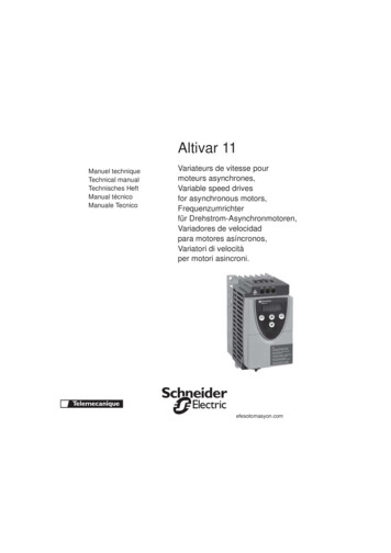
ALTIVAR 11 Start-up 12/0212/02Mount the drive controller (pages 4–5).With the power removed, make the following connections to the drive controller(pages 5–8): Connect the grounding conductors. Connect the line supply. Ensure that it is within the voltage range of the drive controller. Connect the motor. Ensure that its rating corresponds to the drive controller’s voltage.Power up the drive controller, but do not give a run command.Configure the following first level adjustment parameters (pages 9–10): bFr (motor nominal frequency), if it is other than 60 Hz. bFr only appears as a first leveladjustment parameter the first time the drive controller is powered up. ACC (acceleration) and dEC (deceleration) LSP (low speed when the reference is zero) and HSP (high speed when the referenceis at maximum) ItH (motor thermal protection) Preset speeds: SP2, SP3, SP4. Speed reference, if it is other than 0–5 V (0–10 V, 0–20 mA, 4–20 mA).If the factory configuration is not suitable for the application, configure the parameters andI/O assignments in the drC and FUn menus. Refer to the tables beginning on page 10 forthe factory configuration.Remove power from the drive controller, then connect the control wiring via the logic andanalog inputs.Power up the drive controller, then issue a run command via the logic input (page 12).DIMENSIONS G H GaaabCGHØATV11H in.mm in.mmIn.mm in.mmin.mmin.mmU05 UU09 U2.9725.71424.05.01011252.4605.21312 x 0.22x5U18M U2.9725.91475.51382.4605.21312 x 0.22x5U18F1UU29 U U41 U4.71175.71426.21564.21065.21314 x 0.24x52.9725.71424.01012.4605.21312 x 0.22x5ATV11PAll ratings4 c bH 4 2 2002 Schneider Electric All Rights Reserved
ALTIVAR 11 Start-up GuideMounting and Temperature ConditionsVVDED302031USR12/0212/02MOUNTING AND TEMPERATURE CONDITIONS 2 in. (50 mm)Install the drive controller vertically 10 with the output terminals at thebottom. dDo not place the drive controller close to heating sources. 2 in. (50 mm)Leave sufficient free space around the drive controller to ensure that air cancirculate from the bottom to the top of the unit.Leave a minimum of 0.4 in. (10 mm) of free space in front of the drivecontroller.14 to 104 F(-10 to 40 C): d 2 in. (50 mm): no special precautions. d 0 (side-by-side drive controllers): remove the protective cover.104 to 122 F(40 to 50 C): d 2 in. (50 mm): remove the protective cover.122 to 140 F(50 to 60 C): d 2 in. (50 mm): remove the protective cover and derate the drive nominalcurrent by 2.2% for every C above 50 C.ENGLISH d.NOTE: Monitor the tHd parameter (in the SUP menu) during normal operation to verify the drivecontroller thermal state.Refer to instruction bulletin VVDED302026US for information on mounting ATV11P drivecontrollers.BUS VOLTAGE MEASUREMENT PROCEDUREDANGERHAZARDOUS VOLTAGERead and understand the precautions on page 3 before performing this procedure.Failure to follow these instructions will result in death or serious injury.The bus voltage can exceed 400 Vdc. Use appropriately rated measuring equipment whenperforming this procedure. To measure the bus capacitor voltage:1. Disconnect all power from the drive controller.2. Wait 15 minutes to allow the DC bus to discharge.3. Measure the DC bus voltage between the PA ( ) and PC (–) terminals to verify that the DCvoltage is less than 45 Vdc. Refer to “Power Terminals” on page 8 for the location of theterminals.4. If the bus capacitors are not fully discharged, contact your local Schneider Electricrepresentative—do not operate the drive controller. 2002 Schneider Electric All Rights Reserved5
ALTIVAR 11 Start-up GuideElectrical InstallationVVDED302031USR12/0212/02ELECTRICAL INSTALLATIONEnsure that the electrical installation of this drive controller conforms to the appropriate nationaland local codes. Verify that the voltage and frequency of the input supply line and the voltage, frequency,and current of the motor match the rating on the drive controller nameplate.DANGERHAZARDOUS VOLTAGEGround equipment using the provided ground connecting point as shown in the figurebelow. The drive controller panel must be properly grounded before power is applied.Electric shock will result in death or serious injury.Drive ControllerENGLISH Verify that resistance to ground is one ohm orless. Ground multiple controllers as shown inthe figure. Do not loop the ground cables orconnect them in series.Drive ControllerDrive Controller Provide overcurrent protection. To achieve the fault-withstand current rating listed on thedrive controller nameplate, install the line power fuses recommended on the drivecontroller nameplate.WARNINGINADEQUATE OVERCURRENT PROTECTION Overcurrent protective devices must be properly coordinated. The National Electrical Code requires branch circuit protection. Use the fusesrecommended on the drive controller nameplate to achieve published fault withstandcurrent ratings. Do not connect the drive controller to a power feeder whose short circuit capacityexceeds the drive controller withstand fault rating listed on the drive controllernameplate.Failure to follow these instructions can result in death, serious injury, or equipmentdamage. 6Do not use mineral-impregnated cables. Select motor cabling with low phase-to-phase andphase-to-ground capacitance.Motor cables must be at least 20 in. (0.5 m) long.Maximum motor cable length is 50 m (164 ft.) for shielded cable and 100 m (328 ft.) fornon-shielded cable. Verify that the motor is designed for use with AC drive controllers.Cable runs longer than 12.2 m (40 ft.) may require output filters to reduce voltage spikesat the motor terminals.Do not run control, power,or motor wiring in the same conduit. Do not run motor wiring fromdifferent drive controllers in the same conduit. Separate metallic conduit carrying powerwiring from metallic conduit carrying control wiring by at least 3 in. (8 cm). Separate non- 2002 Schneider Electric All Rights Reserved
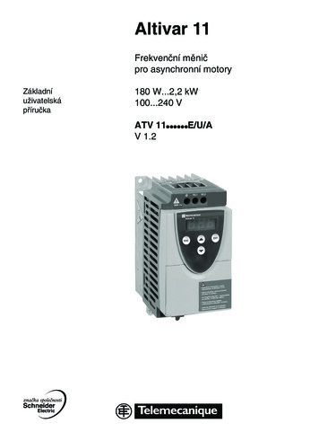
ALTIVAR 11 Start-up GuideWiring Diagram for Factory SettingsVVDED302031USR12/0212/02metallic conduits or cable trays used to carry power wiring from metallic conduit carryingcontrol wiring by at least 12 in. (31 cm). Always cross power and control wiring at rightangles.WARNINGIMPROPER WIRING CONNECTIONS The drive controller will be damaged if input line voltage is applied to the outputterminals (U, V, W). Check the power connections before energizing the drive controller. If replacing another drive controller, verify that all wiring connections to the ATV11 drivecontroller comply with all wiring instructions in this manual.Failure to follow these instructions can result in death, serious injury, or equipmentdamage. Do not immerse motor cables in water.Do not use lightning arrestors or power factor correction capacitors on the output of thedrive controller.Equip all inductive circuits near the drive controller (such as relays, contactors, andsolenoid valves) with electrical noise suppressors, or connect them to a separate circuit.ENGLISH WIRING DIAGRAM FOR FACTORY SETTINGSSingle phase line supply 100–120 VNOTE: The line supply terminals are shown atthe top and the motor terminals are shown atthe bottom. Connect the power terminalsbefore connecting the control terminals. Installsurge suppressors on all inductive circuitslocated near the drive controller or coupled tothe same circuit.ATV11 F1 NL1(4)Single phase line supply 200–230 VATV11 M2 L2L1(4)3-phase line supply 200–240 VATV11 M3 (2)L3 15 VDOLI4LI30VLI1LI2AI1PC / PB 5VPA / PAWUVW1V1U1RC(1)RAL2L1(4)M3aMotor200–230 VSpeedpotentiometer(1) Fault relay contacts for remote indication ofdrive controller status.(2) Internal 15 V. If an external source is used(30 V Max.), connect the 0 V of the source tothe 0 V terminal, and do not use the 15 Vterminal on the drive controller.(3) Meter or low level relay.(4) Refer to drive controller nameplate for recommended fuses. Fast acting or time delayClass J fuses can be used.(5) See bulletin VVDED302026US for precautions and additional information concerningdynamic braking.(3)Braking module andresistor, optional (5) 2002 Schneider Electric All Rights Reserved7
ALTIVAR 11 Start-up GuidePower TerminalsVVDED302031USR12/0212/02POWER TERMINALSMaximum Connection CapacityATV11 2AWGmmlb-inN mU05 , U09 , U18M AWG 141.56.60.75U18F1 , U29 , U41 AWG 1048.91Line power supplyPA( )ENGLISHTightening TorqueLine power supplyPA( )PC(–)MotorconnectionsTo brakingmodule(optional)PC(–)To brakingmodule(optional)MotorconnectionsTerminal 15VLI 4LI 3LI 2LI 1DO 5VAI 10VNot usedRARCCONTROL TERMINALSMaximum connection capacity:AWG 16 (1.5 mm2)Maximum tightening torque:4.4 lb-in (0.5 N m).FunctionElectrical CharacteristicsRCRAFault relay contact(open if there is a fault or thedrive controller is off)Min. switching capacity: 10 mA for 24 VdcMax. switching capacity: 2 A for 250 Vac and 30 Vdc on inductive loadTime constant 0.4 – (inductance/resistance) 7 ms 5 A for 250 Vac and 30 Vdc on resistive loadTime constant 1– (inductance/resistance) 00VI/O common0VAI1Voltage or current analog inputAnalog input 0–5 V or 0–10 V: impedance 40 kΩ, 30 V max.Analog input 0–20 mA or 4–20 mA: impedance 250 Ω (with no externalresistor) 5 VPower supply for referencepotentiometer 2.2 to 10 kΩ Precision: 0–5% Max. current available: 10 mA8 2002 Schneider Electric All Rights Reserved
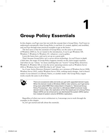
ALTIVAR 11 Start-up GuideProgramming the Drive Electrical CharacteristicsDOPWM open collector analog output at 2 kHZ:Output voltage 30 V max., impedance 1 kΩ, 10 mA max.(can be configured as analog orOpen collector logic output:logic output) voltage 30 V max., impedance 100 kΩ, 50 mA max.LI1LI2LI3LI4Programmable logic inputs Power supply 15 V (max. 30 V), Impedance 5 kΩ State 0 if 5 V, state 1 if 11 V 15 VLogic input power supply 15 V 15% (protected against short circuits and overloads)Maximum current available: 100 mAPROGRAMMING THE DRIVE CONTROLLERExits a menu orparameter, or aborts thedisplayed value andreturns to the previousvalue in the memory ESCENGLISHThree 7-segmentdisplaysEnters a menu or a parameter,or saves the displayedparameter or valueENTReturns to the previousmenu or parameter, orincreases the displayedvalueGoes to the next menu orparameter, or decreases thedisplayed value Pressingordoes not save the choice. To save the displayed choice, pressENT.PROGRAMMING EXAMPLEParameterValue or assignmentENTACC015ESCESCdEC1 flash(save)026The display flashes when avalue is stored.026ENT(Next parameter)Normal display with no fault present and no run command: rdY: Drive controller ready43.0: Display of the parameter selected in the SUP menu (default selection: referencefrequency)dcb: DC injection braking in progressnSt: Freewheel stopIf there is a fault, the display flashes. 2002 Schneider Electric All Rights Reserved9
ALTIVAR 11 Start-up GuideFirst Level Adjustment parametersVVDED302031USR12/0212/02FIRST LEVEL ADJUSTMENT PARAMETERSDisplays drive controller status 1st leveladjustmentparameters Menu: Motor control Menu: Application functions Menu: Monitoring MenusENGLISH The parameters in unshaded boxes can only be modified when the controller is stopped and locked.The parameters in shaded boxes can be modified with the controller operating or stopped.CodeDescriptionAdjustment rangeFactory settingbFrMotor frequency50 or 60 Hz60This parameter is only displayed here the first time the drive controller is powered up. It can be modif
ALTIVAR fi 11 Start-up Guide VVDED302031USR12/02 Dimensions 12/02 EN GL I S H 1. Mount the drive controller (pages 4Œ5). 2. With the power removed, make the following connections to the drive controller (pages 5Œ8): Connect the grounding conductors. Connect the line supply. Ensure that it is with in the voltage range of the drive controller .