Transcription
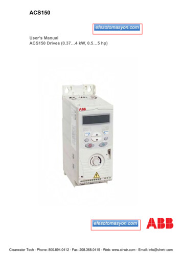
InstructionBulletinBoletín deinstruccionesVVDED302026USR2/0302/2003Raleigh, NC, USADirectivesd'utilisationALTIVAR 11Adjustable Speed Drive ControllersUser’s GuideRetain for Future Use.Conservar para uso futuro.À conserver pour usage ultérieur.Variadores de velocidad ajustableGuía del usuarioVariateurs de vitesseGuide de l’utilisateur
ALTIVAR 11 User’s GuideVVDED302026USR2/0302/2003ALTIVAR 11 Adjustable Speed Drive ControllersENGLISHUser’s GuideESPAÑOLVariadores de velocidad ajustable ALTIVAR 11Guía del usuarioFRANÇAISVariateurs de vitesse ALTIVAR 11Guide de l’utilisateur 2003 Schneider Electric All Rights Reserved3
ALTIVAR 11 User’s US VOLTAGE Read and understand this manual before installing or operatingthe ALTIVAR 11 drive controllers. Installation, adjustment, repair,and maintenance must be performed by qualified personnel. The user is responsible for conforming to all applicable coderequirements with respect to grounding all equipment. Many parts in this drive controller, including printed wiring boards,operate at line voltage. DO NOT TOUCH. Use only electricallyinsulated tools. DO NOT touch unshielded components or terminal strip screwconnections with voltage present. DO NOT short across terminals PA and PC or across the DCcapacitors. Install and close all covers before applying power or starting andstopping the drive controller. Before servicing the drive controller:— Disconnect all power.— Place a “DO NOT TURN ON” label on the drive controllerdisconnect.— Lock the disconnect in the open position. Disconnect all power including external control power that maybe present before servicing the drive controller. WAIT 15MINUTES for the DC bus capacitors to discharge. Then followthe DC bus voltage measurement procedure beginning on page23 to verify that the DC voltage is less than 45 Vdc. The drivecontroller LEDs are not accurate indicators of the absence of DCbus voltage.Failure to follow this instruction will result in death or seriousinjury.4 2003 Schneider Electric All Rights Reserved
VVDED302026USR2/0302/2003ALTIVAR 11 User’s GuideTable of ContentsNorth American (U) Range (ATV11 U) . . . . . . . . . . . . . . . . . . . . . . . . . . . . . . . 7European (E) Range (ATV11 E) . . . . . . . . . . . . . . . . . . . . . . . . . . . . . . . . . . . 7Asian (A) Range (ATV11 A) . . . . . . . . . . . . . . . . . . . . . . . . . . . . . . . . . . . . . . . 7STORING AND SHIPPING . . . . . . . . . . . . . . . . . . . . . . . . . . . . . . . . . . . . . . . . . . . . . 8TECHNICAL CHARACTERISTICS . . . . . . . . . . . . . . . . . . . . . . . . . . . . . . . . . . . . . . . 9DIMENSIONS . . . . . . . . . . . . . . . . . . . . . . . . . . . . . . . . . . . . . . . . . . . . . . . . . . . . . . . 16MOUNTING AND TEMPERATURE CONDITIONS . . . . . . . . . . . . . . . . . . . . . . . . . . 17MOUNTING DRIVE CONTROLLERS WITH BASE PLATES . . . . . . . . . . . . . . . . . . 19MOUNTING THE EMC PLATE . . . . . . . . . . . . . . . . . . . . . . . . . . . . . . . . . . . . . . . . . 20MOUNTING IN A TYPE 12 OR IP54 METAL ENCLOSURE . . . . . . . . . . . . . . . . . . . 20Calculating Enclosure Size . . . . . . . . . . . . . . . . . . . . . . . . . . . . . . . . . . . . . . . . . . 20Ventilation . . . . . . . . . . . . . . . . . . . . . . . . . . . . . . . . . . . . . . . . . . . . . . . . . . . . . . . 22BUS VOLTAGE MEASUREMENT PROCEDURE . . . . . . . . . . . . . . . . . . . . . . . . . . . 23ELECTRICAL INSTALLATION . . . . . . . . . . . . . . . . . . . . . . . . . . . . . . . . . . . . . . . . . . 23POWER TERMINALS . . . . . . . . . . . . . . . . . . . . . . . . . . . . . . . . . . . . . . . . . . . . . . . . 25RECOMMENDED FUSES . . . . . . . . . . . . . . . . . . . . . . . . . . . . . . . . . . . . . . . . . . . . . 27CONTROL TERMINALS . . . . . . . . . . . . . . . . . . . . . . . . . . . . . . . . . . . . . . . . . . . . . . 28WIRING DIAGRAM . . . . . . . . . . . . . . . . . . . . . . . . . . . . . . . . . . . . . . . . . . . . . . . . . . 29EUROPEAN COMMUNITY EMC DIRECTIVE . . . . . . . . . . . . . . . . . . . . . . . . . . . . . . 30LOGIC INPUT APPLICATION FUNCTIONS . . . . . . . . . . . . . . . . . . . . . . . . . . . . . . . 322-Wire Control . . . . . . . . . . . . . . . . . . . . . . . . . . . . . . . . . . . . . . . . . . . . . . . . . . . .3-Wire Control . . . . . . . . . . . . . . . . . . . . . . . . . . . . . . . . . . . . . . . . . . . . . . . . . . . .Operating Direction (Forward / Reverse) . . . . . . . . . . . . . . . . . . . . . . . . . . . . . . .Preset Speeds . . . . . . . . . . . . . . . . . . . . . . . . . . . . . . . . . . . . . . . . . . . . . . . . . . .Fault Reset . . . . . . . . . . . . . . . . . . . . . . . . . . . . . . . . . . . . . . . . . . . . . . . . . . . . . .Second Ramp . . . . . . . . . . . . . . . . . . . . . . . . . . . . . . . . . . . . . . . . . . . . . . . . . . . .323232333333DO OUTPUT APPLICATION FUNCTIONS . . . . . . . . . . . . . . . . . . . . . . . . . . . . . . . . 34Current in the Motor (AO) . . . . . . . . . . . . . . . . . . . . . . . . . . . . . . . . . . . . . . . . . . .Motor Frequency (AO) . . . . . . . . . . . . . . . . . . . . . . . . . . . . . . . . . . . . . . . . . . . . .Frequency Threshold Reached (LO) . . . . . . . . . . . . . . . . . . . . . . . . . . . . . . . . . .Reference Reached (LO) . . . . . . . . . . . . . . . . . . . . . . . . . . . . . . . . . . . . . . . . . . .Current Threshold Reached (LO) . . . . . . . . . . . . . . . . . . . . . . . . . . . . . . . . . . . . .DO Output Wiring Diagram . . . . . . . . . . . . . . . . . . . . . . . . . . . . . . . . . . . . . . . . . .Configuration of the Analog Input . . . . . . . . . . . . . . . . . . . . . . . . . . . . . . . . . . . . .Wiring Diagram for the Analog Input . . . . . . . . . . . . . . . . . . . . . . . . . . . . . . . . . . . 2003 Schneider Electric All Rights Reserved34343434343535365ENGLISHINTRODUCTION . . . . . . . . . . . . . . . . . . . . . . . . . . . . . . . . . . . . . . . . . . . . . . . . . . . . . 7
ALTIVAR 11 User’s GuideTable of G . . . . . . . . . . . . . . . . . . . . . . . . . . . . . . . . . . . . . . . . . . . . . . . . . . . . 37Precautions . . . . . . . . . . . . . . . . . . . . . . . . . . . . . . . . . . . . . . . . . . . . . . . . . . . . . . 37Programming the Drive Controller: E (European) and U (North American)Ranges . . . . . . . . . . . . . . . . . . . . . . . . . . . . . . . . . . . . . . . . . . . . . . . . . . . . . . 38Programming the Drive Controller: A (Asian) Range . . . . . . . . . . . . . . . . . . . . . . 39ACCESS TO MENUS . . . . . . . . . . . . . . . . . . . . . . . . . . . . . . . . . . . . . . . . . . . . . . . . . 40FIRST LEVEL ADJUSTMENT PARAMETERS . . . . . . . . . . . . . . . . . . . . . . . . . . . . . 41drC MOTOR CONTROL MENU . . . . . . . . . . . . . . . . . . . . . . . . . . . . . . . . . . . . . . . . . 43FUn APPLICATION FUNCTIONS MENU . . . . . . . . . . . . . . . . . . . . . . . . . . . . . . . . . . 45Incompatible Application Functions . . . . . . . . . . . . . . . . . . . . . . . . . . . . . . . . . . . . 46tCC Menu . . . . . . . . . . . . . . . . . . . . . . . . . . . . . . . . . . . . . . . . . . . . . . . . . . . . . . . 47rrS, PS2, and rSF Menus . . . . . . . . . . . . . . . . . . . . . . . . . . . . . . . . . . . . . . . . . . . 48rP2, StP, and brA Menus . . . . . . . . . . . . . . . . . . . . . . . . . . . . . . . . . . . . . . . . . . . . 50AdC and SFt Menus . . . . . . . . . . . . . . . . . . . . . . . . . . . . . . . . . . . . . . . . . . . . . . . 51FLr and dO Menus . . . . . . . . . . . . . . . . . . . . . . . . . . . . . . . . . . . . . . . . . . . . . . . . 53Atr, LSr, and nPL Menus . . . . . . . . . . . . . . . . . . . . . . . . . . . . . . . . . . . . . . . . . . . . 55bFr, IPL, SCS, and FCS Menus . . . . . . . . . . . . . . . . . . . . . . . . . . . . . . . . . . . . . . 57SUP DISPLAY MENU . . . . . . . . . . . . . . . . . . . . . . . . . . . . . . . . . . . . . . . . . . . . . . . . . 58MAINTENANCE AND TROUBLESHOOTING . . . . . . . . . . . . . . . . . . . . . . . . . . . . . . 59Precautions . . . . . . . . . . . . . . . . . . . . . . . . . . . . . . . . . . . . . . . . . . . . . . . . . . . . . . 59Routine Maintenance . . . . . . . . . . . . . . . . . . . . . . . . . . . . . . . . . . . . . . . . . . . . . . 59Fault Detection . . . . . . . . . . . . . . . . . . . . . . . . . . . . . . . . . . . . . . . . . . . . . . . . . . . 59Procedure 1: Checking the Supply Voltage . . . . . . . . . . . . . . . . . . . . . . . . . . . . . . 60Procedure 2: Checking the Peripheral Equipment . . . . . . . . . . . . . . . . . . . . . . . . 60LIST OF FAULTS AND CORRECTIVE ACTION . . . . . . . . . . . . . . . . . . . . . . . . . . . . 62Drive Controller Does Not Start, No Fault Displayed . . . . . . . . . . . . . . . . . . . . . . 63CONFIGURATION AND SETTINGS TABLES . . . . . . . . . . . . . . . . . . . . . . . . . . . . . . 646 2003 Schneider Electric All Rights Reserved
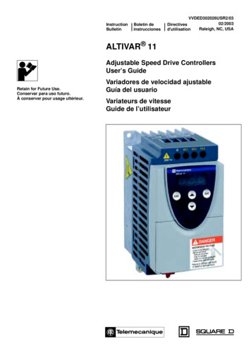
ALTIVAR 11 User’s TION ENGLISHThe ALTIVAR 11 (ATV11) family of adjustable speed AC drivecontrollers is used for controlling three-phase asynchronous motors.The controllers range from:0.25 to 3 hp (0.37 to 2.2 kW), 208/230/240 V, single-phase input0.25 to 3 hp (0.37 to 2.2 kW), 208/230/240 V, three-phase input0.25 to 1 hp (0.37 to 0.75 kW), 100/115/120 V, single-phase inputATV11 controllers have been designed for the global marketplacewith three regional adaptations. Each version of the product has thesame wiring configuration and functionality. The variations among theregional versions are summarized in the following sections.North American (U) Range (ATV11 U) Designed for the North American market.Current ratings meet or exceed NEC requirements (seepages 9–11).European (E) Range (ATV11 E) Designed for the European market. Has an integrated EMC filter to meet European CE requirements.Available only in 230 V single-phase input line voltage.Current ratings have been adapted to meet European standards(see pages 9–11).Asian (A) Range (ATV11 A) Designed for the Asian market. Speed reference potentiometer and run/stop buttons have beenintegrated onto the keypad display for local operation (see pages39, 47, and 56). Logic inputs can be configured for negative logic (see page 56).Current ratings have been adapted to meet Asian standards (seepages 9–11).This instruction bulletin covers the technical characteristics,installation, wiring, programming, and maintenance of all ATV11 drivecontrollers. 2003 Schneider Electric All Rights Reserved7
ALTIVAR 11 User’s GuideStoring and ShippingVVDED302026USR2/0302/2003RECEIVING AND PRELIMINARY INSPECTIONENGLISHBefore installing the ATV11 drive controller, read this manual andfollow all precautions. Before removing the drive controller from its packaging, verify thatthe carton was not damaged in shipping. Carton damage usuallyindicates improper handling and the potential for device damage.If any damage is found, notify the carrier and yourSquare D/Schneider Electric representative. After removing the drive controller from its packaging, visuallyinspect the exterior for shipping damage. If any is found, notify thecarrier and your sales representative. Do not install a damageddevice. Verify that the drive controller nameplate and label conform to thepacking slip and corresponding purchase order.\CAUTIONDAMAGED EQUIPMENTDo not operate or install any drive controller that appears damaged.Failure to follow this instruction can result in injury orequipment damage.STORING AND SHIPPINGIf the drive controller is not being immediately installed, store it in aclean, dry area with an ambient temperature between -25 and 69 C(-13 to 156 F). If the drive controller must be shipped to anotherlocation, use the original shipping carton and packing material toprotect it.8 2003 Schneider Electric All Rights Reserved
ALTIVAR 11 User’s GuideTechnical CharacteristicsVVDED302026USR2/0302/2003TECHNICAL CHARACTERISTICSSingle-Phase Supply Voltage: 200/240 V -15%, 10%, 50/60 Hz;Three-Phase ive ControllerMax.Short Circuit NominalTransientRatingCurrentCurrent3AENGLISHTable 1:kAAPowerDissipatedat Nominal Catalog Number4LoadAWNorth American (U) 43.623ATV11 U09M2U0.7519.914.66.343ATV11 5101ATV11HU41M2UAsian (A) .625ATV11 U09M2A0.7519.914640ATV11 7ATV11HU41M2AEuropean (E) 13.120.5ATV11 U09M2E0.550.756.3134.529ATV11 U12M2E0.7518.613.65.437ATV11 .496ATV11HU41M2E1Power ratings are for a switching frequency of 4 kHz in continuous operation. The switching frequency isadjustable from 2 to 16 Hz. Above 4 kHz, the drive controller will reduce the switching frequency if an excessivetemperature rise occurs. The temperature rise is sensed by a PTC probe in the power module. Derate thenominal drive current as follows for continuous operation above 4 kHz: 10% for 8 kHz; 20% for 12 kHz; 30% for16 kHz.2Nominal voltage values: 208 V for the North American (U) Range; 200 V for the Asian (A) Range; 230 V for theEuropean (E) Range.3For 60 seconds.4The symbol “ ” in a catalog number indicates that the drive controller is available in two versions. For drivecontrollers with a heatsink, replace the “ ” with an “H” (for example, ATV11HU09M2E). For drive controllers witha base plate, replace the “ ” with a “P” (for example, ATV11PU09M2E). 2003 Schneider Electric All Rights Reserved9
ALTIVAR 11 User’s GuideTechnical CharacteristicsENGLISHTable 2:Three-P
VVDED302026USR2/03 ALTIVAR 11 User’s Guide 02/2003 Introduction 7 ENGLISH INTRODUCTION The ALTIVAR 11 (ATV11) family of adjustable speed AC drive controllers is used for controlling three-phase asynchronous motors. The controllers range from: 0.25 to 3 hp (0.37 to 2.2 kW), 208/230/240 V, single-phase inputFile Size: 518KBPage Count: 70