Transcription
Altivar 11Manuel techniqueTechnical manualTechnisches HeftManual técnicoManuale TecnicoVariateurs de vitesse pourmoteurs asynchrones,Variable speed drivesfor asynchronous motors,Frequenzumrichterfür Drehstrom-Asynchronmotoren,Variadores de velocidadpara motores asíncronos,Variatori di velocitàper motori asincroni.efesotomasyon.com
OWLYDU 9DULDWHXUV GH YLWHVVH SRXU PRWHXUV DV\QFKURQHV3DJH ,6 d1 5)9DULDEOH VSHHG GULYHV IRU DV\QFKURQRXV PRWRUV3DJH ,6/*1(6HLWH &678('3iJLQD /2f 36(3DJLQD 21, / 7,)UHTXHQ]XPULFKWHU I U 'UHKVWURP V\QFKURQPRWRUHQ9DULDGRUHV GH YHORFLGDG SDUD PRWRUHV DVtQFURQRV9DULDWRUL GL YHORFLWj SHU PRWRUL DVLQFURQLefesotomasyon.com1
When the drive is powered up, the power components and some of the control components areconnected to the line supply. It is extremely dangerous to touch them. The drive cover must be keptclosed.In general, the drive power supply must be disconnected before any operation on either the electricalor mechanical parts of the installation or machine.After the ALTIVAR has been switched off and the display has disappeared completely, wait for 10minutes before working on the equipment. This is the time required for the capacitors to discharge.The motor can be stopped during operation by inhibiting start commands or the speed reference whilethe drive remains powered up. If personnel safety requires prevention of sudden restarts, thiselectronic locking system is not sufficient: fit a cut-off on the power circuit. ,6/*1(The drive is fitted with safety devices which, in the event of a fault, can shut down the drive andconsequently the motor. The motor itself may be stopped by a mechanical blockage. Finally, voltagevariations, especially line supply failures, can also cause shutdowns.If the cause of the shutdown disappears, there is a risk of restarting which may endanger certainmachines or installations, especially those which must conform to safety regulations.In this case the user must take precautions against the possibility of restarts, in particular by using alow-speed detector to cut off power to the drive if the motor performs an unprogrammed shutdown.The drive must be installed and set up in accordance with both international and national standards.Bringing the device into conformity is the responsibility of the systems integrator who must observethe EMC directive among others within the European Union.The specifications contained in this document must be applied in order to comply with the essentialrequirements of the EMC directive.The Altivar 11 must be considered as a component: it is neither a machine nor a device ready for usein accordance with European directives (machinery directive and electromagnetic compatibilitydirective). It is the responsibility of the end user to ensure that the machine meets these standards.The products and equipment described in this document may be changed or modified at any time,either from a technical point of view or in the way they are operated. Their description can in no waybe considered contractual.62efesotomasyon.com
&RQWHQWVSteps for Setting Up the Drive 64Factory Configuration 65Drive References 66Mounting 70Wiring 74Basic Functions 82Configurable I/O Application Functions 83Setup - Preliminary Recommendations 87Programming 881st Level Adjustment Parameters 91drC Motor Control Menu 94FUn Application Functions Menu 98SUP Display Menu 114Maintenance 116Faults - Causes - Remedies 117Configuration/Settings Tables 119efesotomasyon.com63 ,6/*1(
6WHSV IRU 6HWWLQJ 8S WKH 'ULYH 'HOLYHU\ RI WKH GULYH Check that the drive reference printed on the label is the same as that on the delivery notecorresponding to the purchase order. Remove the Altivar 11 from its packaging and check that it has not been damaged in transit. )LW WKH GULYH &RQQHFW WKH IROORZLQJ WR WKH GULYH ,6/*1( The line supply, ensuring that it is: ZLWKLQ WKH YROWDJH UDQJH RI WKH GULYH YROWDJH IUHH The motor, ensuring that its coupling corresponds to the line voltage The control via the logic inputs The speed reference via the logic or analog inputs 6ZLWFK RQ WKH GULYH EXW GR QRW JLYH D UXQ FRPPDQG &RQILJXUH WKH IROORZLQJ The nominal frequency (bFr) of the motor, if it is other than 50 Hz for the E and A ranges or other than60 Hz for the U range (only appears the first time the drive is switched on). The ACC (Acceleration) and dEC (Deceleration) parameters. The LSP (Low speed when the reference is zero) and HSP (High speed when the reference ismaximum) parameters. The ItH parameter (Motor thermal protection). The preset speeds SP2-SP3-SP4. The speed reference if it is other than 0 - 5 V (0 -10V or 0 -20mA or 4 -20mA). &RQILJXUH WKH IROORZLQJ LQ WKH GU& PHQXThe motor parameters, only if the factory configuration of the drive is not suitable. 6HW WKH IROORZLQJ LQ WKH )8Q PHQXThe application functions, only if the factory configuration of the drive is not suitable, for example thecontrol mode: 3-wire, or 2-wire transitional, or 2-wire level detection, or 2-wire level detection withforward priority, or local control for the A range.7KH XVHU PXVW HQVXUH WKDW WKH SURJUDPPHG IXQFWLRQV DUH FRPSDWLEOH ZLWK WKH ZLULQJGLDJUDP XVHG 6WDUW WKH GULYH64efesotomasyon.com
)DFWRU\ &RQILJXUDWLRQ)DFWRU\ VHWWLQJVThe Altivar 11 is factory-set for the most common operating conditions: Display: drive ready (rdY) motor stopped, and motor frequency reference in running Motor frequency (bFr): 50 Hz for the E and A ranges, 60 Hz for the U range Motor voltage (UnS): 230 V Ramps (ACC, dEC): 3 seconds Low speed (LSP): 0 Hz High speed (HSP): 50 Hz for the E and A ranges, 60 Hz for the U range Frequency loop gain: standard Motor thermal current (ItH) nominal motor current (value depending on drive rating) Standstill injection braking current 0.7 x nominal drive current, for 0.5 seconds Automatic adaptation of the deceleration ramp in the event of overvoltage on braking No automatic restarting after a fault Switching frequency 4 kHz Logic inputs:- LI1, LI2 (2 directions of operation): 2-wire transitional control, LI1 forward, LI2 reverse, inactivefor the Asia range- LI3, LI4: 4 preset speeds (speed 1 speed reference or LSP, speed 2 10 Hz, speed 3 25 Hz,speed 4 50 Hz) Analog input:- AI1 (0 5 V): 5 V speed range, inactive for the Asia range. Relay R1: the contact opens in the event of a fault (or drive off) Analog/logic output DO: as an analog output, image of the motor frequency VLD UDQJHWhen they leave the factory, ATV 11//////A drives are supplied with local control activated: the RUN,STOP buttons and the drive potentiometer are active. Logic inputs LI1 and LI2 and analog input AI1 areinactive.If the above values are compatible with the application, the drive can be used without changing thesettings.efesotomasyon.com65 ,6/*1(
'ULYH 5HIHUHQFHV6LQJOH SKDVH VXSSO\ YROWDJH « 9 ]3-phase motor 200.240 VMotorMainsAltivar 11PowerMax. lineindicated on current (2)plate (1)Max.Nominalprospective currentline IscMax.transientcurrent (3)PowerReference (4)dissipated atnominal loadkW/HPkAAAW11.11.61212.13.120.529A ,6/ (XURSH UDQJH* 0.18 / 0.25 2.91( 0.37 / 0.55.30.55 / 0.756.3134.50.75 / 18.613.65.4371.5 / 214.816.810.2722.2 / 320.819.614.4960.18 / 0.253.311.42.1140.37 / 0.5612.43.6250.75 / 19.9146401.5 / 217.117.511.2782.2 / 324.11101597 VLD UDQJH PHULFD UDQJH0.18 / 0.253.311.62.414.50.37 / 0.5612.43.6230.75 / 19.914.66.3431.5 / 217.117.511.2772.2 / 324.1110.61510166 79 8 0 ( 79 /8 0 ( 79 /8 0 ( 79 /8 0 ( 79 8 0 ( 79 8 0 ( 79 8 0 79 /8 0 79 /8 0 79 8 0 79 8 0 79 8 0 8 79 /8 0 8 79 /8 0 8 79 8 0 8 79 8 0 8efesotomasyon.com
'ULYH 5HIHUHQFHV(1) These power ratings are for a switching frequency of 4 kHz, in continuous operation. The switchingfrequency is adjustable from 2 to 16 kHz.Above 4 kHz, the drive will reduce the switching frequency if an excessive temperature rise occurs.The temperature rise is controlled by a PTC probe in the power module. Nonetheless, deratingshould be applied to the nominal drive current if operation above 4kHz needs to be continuous: 10% derating for 8 kHz 20% derating for 12 kHz 30% derating for 16 kHz ,6/*1((2) Nominal voltage values: 230 V for the Europe range, 200 V for the Asia range and208 V for the America range.(3) For 60 seconds.(4) Drives whose reference contains a / are available in two versions: on heatsink, replace the / with an H (ATV11HU09M2E for example) on base plate, replace the / with a P (ATV11PU09M2E for example)efesotomasyon.com67
'ULYH 5HIHUHQFHV SKDVH VXSSO\ YROWDJH « 9 ]3-phase motor 200.230 VMotorMainsAltivar 11Max. linePowerindicated on current (2)plate (1)NominalMax.prospective currentline IscMax.transientcurrent (3)Reference (4)Powerdissipated atnominal loadkW/HPkAAW VLD UDQJH,6/ 0.18 / 0.25*1 0.37 / 0.5(AA1.851.42.113.53.652.43.6240.75 / 16.3546381.5 / 21157.511.2752.2 / 315.25101594 PHULFD UDQJH0.18 / 0.251.851.62.413.50.37 / 0.53.652.43.6240.75 / 16.354.66.3381.5 / 21157.511.2752.2 / 315.2510.61594 79 8 0 79 /8 0 79 /8 0 79 8 0 79 8 0 79 8 0 8 79 /8 0 8 79 /8 0 8 79 8 0 8 79 8 0 8(1) These power ratings are for a switching frequency of 4 kHz, in continuous operation. The switchingfrequency is adjustable from 2 to 16 kHz.Above 4 kHz, the drive will reduce the switching frequency if an excessive temperature rise occurs.The temperature rise is controlled by a PTC probe in the power module. Nonetheless, deratingshould be applied to the nominal drive current if operation above 4kHz needs to be continuous: 10% derating for 8 kHz, 20% for 12 kHz, 30% for 16 kHz(2) Nominal voltage values: 200 V for the Asia range and 208 V for the America range.(3) For 60 seconds.(4) Drives whose reference contains a / are available in two versions: on heatsink, replace the / with an H (ATV11HU09M3A for example) on base plate, replace the / with a P (ATV11PU09M3A for example)68efesotomasyon.com
'ULYH 5HIHUHQFHV6LQJOH SKDVH VXSSO\ YROWDJH « 9 ]3-phase motor 200.230 VMotorMainsAltivar 11Max. linePowerindicated on current (2)plate (1)NominalMax.prospective currentline IscMax.transientcurrent (3)Reference (4)Powerdissipated atnominal loadkW/HPkAAWAA VLD UDQJH 0.18 / 0.25611.42.1140.37 / 0.5912.43.6250.75 / 11814640 PHULFD UDQJH0.18 / 0.25611.62.414.50.37 / 0.5912.43.6230.75 / 11814.66.343 79 8 ) 79 /8 ) 79 8 ) 79 8 ) 8 79 /8 ) 8 79 8 ) 8(1) These power ratings are for a switching frequency of 4 kHz, in continuous operation. The switchingfrequency is adjustable from 2 to 16 kHz.Above 4 kHz, the drive will reduce the switching frequency if an excessive temperature rise occurs.The temperature rise is controlled by a PTC probe in the power module. Nonetheless, deratingshould be applied to the nominal drive current if operation above 4kHz needs to be continuous: 10% derating for 8 kHz, 20% for 12 kHz, 30% for 16 kHz(2) Values for 100 V nominal voltage.(3) For 60 seconds.(4) Drives whose reference contains a / are available in two versions: on heatsink, replace the / with an H (ATV11HU09F1A for example) on base plate, replace the / with a P (ATV11PU09F1A for example)efesotomasyon.com69 ,6/*1(
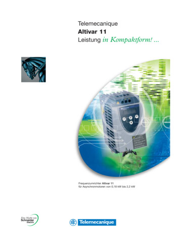
0RXQWLQJ'LPHQVLRQV DQG ZHLJKWVG HH GaATV 11H c b ,6/*1( 4 2aammbmmc (1)mmGmmHmmØmmweightkgU05// E, A, U ranges7214210160 1131 12x50.70U09// E range7214212560 1120 12x50.85U09// A, U ranges7214212560 1131 12x50.85U12// E rangeU18M/ E range7214213860 1120 12x50.92U18M/ A range7214213860 1131 12x50.92U18M/ U range7214713860 1131 12x50.95U18F1 A, U rangesU29// E, A, U rangesU41// E, A, U ranges117142156106 0.5 131 14x51.6ATV 11Pammbmmc (1)mmGmmHmmØmmweightkgAll ratings7214210160 1131 12x50.67(1) For drives in the A range (Asia), add 7 mm for the protruding potentiometer button.70efesotomasyon.com
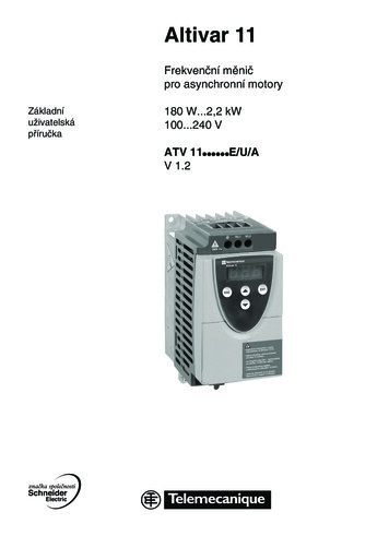
0RXQWLQJ0RXQWLQJ DQG WHPSHUDWXUH FRQGLWLRQV 50 mmInstall the unit vertically, at 10 .Do not place it close to heating elements.Leave sufficient free space to ensure that the air required for coolingpurposes can circulate from the bottom to the top of the unit. d dFree space in front of unit: 10 mm minimum. 50 mmWhen IP20 protection is adequate, we recommend that the protective coveron the top of the drive be removed, as shown below. From -10 C to 40 C: d 50 mm: no special precautions. d 0 (mounted side by side): remove the protective cover on the top of the drive,as shown below (the degree of protection becomes IP20). From 40 C to 50 C: d 50 mm: remove the protective cover on the top of the drive, as shown below(the degree of protection becomes IP20).If the cover is left on, derate the nominal drive current by 2.2% for every Cabove 40 C. d 0: remove the protective cover on the top of the drive, as shown below (thedegree of protection becomes IP20), and derate the nominal drive current by2.2% for every C above 40 C. From 50 C to 60 C: d 50 mm: remove the protective cover on
The Altivar 11 must be considered as a component: it is neither a machine nor a device ready for use in accordance with European directives (machinery directive and electromagnetic compatibility directive). It is the responsibility of the end user to ensure that the machine meets these standards. The products and equipment described in this document may be changed or modified at any time .File Size: 692KBPage Count: 62