Transcription
Resettable PPTC Datasheet250R SeriesRadial LeadedRoHSDescription he 250R Series is designed to protect against short duration highTvoltage fault currents (power cross or power induction surge)typically found in telecom applications (250Vrms). The series canbe used to help telecom networking equipment meet theprotection requirements specified in ITU K.20 and K.21.Features 0 .08 – 0.18 hold currentrange, 60VDC operatingvoltage 250VAC interrupt rating B inned and sorted narrowresistance ranges available RoHS-compliant, Lead-Freeand Halogen-Free* Fast time–to-tripApplicationsAdditional Information Customer PremisesEquipment (CPE) LAN/WAN equipment C entral Office (CO)/ telecomcentersResourcesAccessories Access equipmentSamplesAgency ApprovalsAgencyAgency File NumberE183209R50120008Electrical CharacteristicsPart NumberI hold(A)I trip(A)VmaxVint / VopI 0250/60250/6033333310Maximum Time To TripResistancePdtyp. (W) Current (A) Time (Sec.) R (Ω) R (Ω) .52014475.4830.822897.510.562.23316161416144Agency ApprovalsXXXXXXXXXXXXXXNote: Items with T at end of part number pre-tripped device. See Part Ordering Number System section of this data sheet for additional information.I hold Hold current: maximum current device will pass without tripping in 20 C still air.R min Minimum resistance of device in initial (un-soldered) state.I trip Trip current: minimum current at which the device will trip in 20 C still air.R typ Typical resistance of device in initial (un-soldered) state.Vint Maximum voltage the device can withstand without damage at rated current (I max)R 1max Maximum resistance of device at 20 C measured one hour after tripping.Vop The device regular operation voltage* Effective February 11, 2010 onward, all 600R PTC products will be manufactured Halogen Free (HF). ExistingI max Maximum fault current device can withstand without damage at rated voltage (Vmax)Non-Halogen Free 600R PTC products may continue to be sold, until supplies are depleted. This change willP d Power dissipated from device when in the tripped state at 20 C still air.have no effect on 600R product specifications or performance.Warning Users shall independently assess the suitability of these devices for each of their applications Operation of these devices beyond the stated maximum ratings could result in damage to the devices and lead to electrical arcing and/or fire These devices are intended to protect against the effects of temporary over-current or over-temperature conditions and are not intended to perform as protective devices where such conditions are expected to berepetitive or prolonged in duration Exposure to silicon-based oils, solvents, electrolytes, acids, and similar materials can adversely affect the performance of these PPTC devices These devices undergo thermal expansion under fault conditions, and thus shall be provided with adequate space and be protected against mechanical stresses Circuits with inductance may generate a voltage (L di/dt) above the rated voltage of the PPTC device.1 2021 Littelfuse, Inc.Specifications are subject to change without notice.Revised: GD. 05/07/21
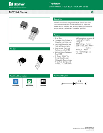
Resettable PPTC Datasheet250R SeriesRadial LeadedTemperature ReratingAmbient Operation Temperature-40 C-20 C0 C20 C40 CPart .060.100.120.1670 C85 .030.050.060.083170%1000150%Percentage of Rated Current100Time to trip (sec)60 CTemperature Rerating CurveAverage Time Current Curves101BCD0,1A0,010,00150 CHold Current (A)130%110%90%70%50%30%10%0,1110-40 -30 -20Fault Current (A)Ihold (A)ABCD0.180.1450.120.8001020 30 40Temperature ( C)50607080Note: Typical Temperature rerating curve, refer to table for derating dataThe average time current curves and Temperature Rerating curve performance is affected by a numberor variables, and these curves provided as guidance only. Customer must verify the performance in theirapplication.Curve Designation-102 2021 Littelfuse, Inc.Specifications are subject to change without notice.Revised: GD. 05/07/21
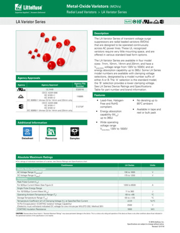
Resettable PPTC Datasheet250R SeriesRadial LeadedAgency Specification Selection Guide For Telecom and Networking ApplicationsProductLightningPower Cross250R120250R145ITU K.20/21/45 – 1.5kV 10/700μsITU K.20/21/45 – 4kV 10/700μs*ITU K.20/21/45 – 1.5kV 10/700μsITU K.20/21/45 – 4kV 10/700μs*Telcordia GR – 974 – 1.0kV 10/1000μsITU K.20/21/45 – 230Vac, 10ΩITU K.20/21/45 – 600Vac, 600ΩITU K.20/21/45 – 230Vac, 10ΩITU K.20/21/45 – 600Vac, 600ΩTelcordia GR – 974- 283Vac, 10A250R180*Devices should be independently evaluated and tested for use in any specific applicationProtection Application GuideRegion/SpecificationApplicationSouth America/Asia/Europe ITU K.45*Access network equipment, Remote terminalRepeaters, WAN equipment, Cross –connectSouth America/Asia/Europe ITU K.21Customer and IT equipment, Analog modemsADSL, xDSL, Phone sets, PBX systems, Internet appliances, POS terminalsSouth America/Asia/Europe ITU K.20Central Office, POTS/ISDN linecards, T1/E1/J1 linecards,ADSL/VDSL splitters, CSU/DSU,North America Telcordia R145250R120250R080*Primary protection modules,MDF modules, Network interfaceSouth America/Asia/Europe ITU K.20North America Telcordia GR-1089South America/Asia/EuropeITU K.20 and K.21-Device Selection*Intrabuilding communication systems, LAN, VOIP cards, Local loop handsets,LAN Intrabuilding power cross, Protection, LAN equipment, IP phone*Resistance binned parts are recommendedSoldering Parameters - Wave SolderingConditionPeak Temp/ Duration Time 220 CPreheat 140 C 180 CStorage ConditionWave Soldering260 C 5 Sec2 Sec 20 Sec180 Sec 210 Sec0 C 35 C, 70%RHSoldering260Cooling220Temperature ( C)Note: R ecommended soldering methods: heat element oven or N2 environment for lead–free D evices are designed to be wave soldered to the bottom side of the board. D evices can be cleaned using standard industry methods and solvents. T his profile can be used for lead-free device I f soldering temperatures exceed the recommended profile, devices may not meet theperformance requirements.1901600Preheating180 to 2102 to 520-30Time(s)3 2021 Littelfuse, Inc.Specifications are subject to change without notice.Revised: GD. 05/07/21
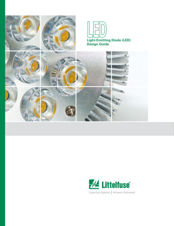
Resettable PPTC DatasheetFigure 1250R SeriesCAFigure 2ARadial LeadedBPhysical SpecificationsSolderingCharacteristicsInsulating MaterialDevice LabelingFigure 1AEnvironmental SpecificationsDOperating TemperatureTin-plated CopperSolderability per MIL–STD–202,Method 208Cured, flame retardant epoxy polymermeets UL94V-0 requirements.Marked with 'LF', voltage, current rating,and date code.Lead MaterialD125 CFEPassive Aging65 C/85 C, 1000 hoursHumidity Aging 85 C, 85% R.H,.1000 hoursThermal ShockMIL–STD–202, Method 107 125 C to -55 C 10 timesSolvent ResistanceMIL–STD–202, Method 215Moisture Sesitivity LevelLevel 1, J–STD–020Part Marking SystemAC250LittelfuseTrademarkBLittelfuseVoltage RatingTrademarkCurrent RatingDate Code(Contact Littelfusefor additionalinformation)080XXXXB250Voltage RatingCurrent RatingDate Code(Contact Littelfusefor additionalinformation)120XXXXDDFEFEFigure 1Figure 2APart 250R120-R2250R145250R180LittelfuseTrademark-40 C to 85 CMaximum Device SurfaceTemperatureEin Tripped StateFigure 2DimensionsCBFigure1222221LittelfuseVoltage RatingTrademarkCurrent RatingDate Code(Contact Littelfusefor additionalinformation)BCDEPhysical .650.650.650.650.650.650.650.230.270.270.27 250120XXXX0.270.270.37Voltage RatingCurrent RatingDate Code(Contact Littelfusefor additionalinformation)Lead RNING: Users shall independently assess the suitability of these devices for each of their applications Operation of these devices beyond the stated maximum ratings could result in damage to the devices and lead to electrical arcing and/or fire These devices are intended to protect against the effects of temporary over-current or over-temperature conditions and are not intended to perform as protective devices where such conditions are expected to berepetitive or prolonged in duration Exposure to silicon-based oils, solvents, electrolytes, acids, and similar materials can adversely affect the performance of these PPTC devices These devices undergo thermal expansion under fault conditions, and thus shall be provided with adequate space and be protected against mechanical stresses Circuits with inductance may generate a voltage (L di/dt) above the rated voltage of the PPTC device.Part Ordering Number System250 R 120 - RA Z RPackaging StyleBlank: BulkR: Tape & AmmoQuantity Code: F 200 M 1000 U 500 Z 1200SeriesRx: Resistance Range (x A-Z or 1-9) [not applicable for all parts]T: Pre-tripped Device (Optional)IHOLD Current Code (Refer to Packaging or Electrical Characteristics tables)R: RadialPeak Voltage Rating4 2021 Littelfuse, Inc.Specifications are subject to change without notice.Revised: GD. 05/07/21
Resettable PPTC Datasheet250R SeriesRadial LeadedPackagingPart NumberOrdering F250R180MRIhold (A)Ihold 450.180180Packaging OptionQuantityQuantity & Packaging CodesBulkTape and AmmoBulkTape and AmmoTape and AmmoTape and AmmoTape and AmmoTape and AmmoBulkTape and RZRZRFMRTape and Ammo SpecificationsDevices taped using EIA468-B/IE286-2 standards. See table below and Figure 1 for details.DimensionEIA MarkIEC tt1ΔhΔpP1FCarrier tape widthHold down tape widthTop distance between tape edgesSprocket hole positionSprocket hole diameter*Abscissa to plane (straight lead)Abscissa to plane (kinked lead)Abscissa to topOverall width without lead protrusionOverall width with lead protrusionLead protrusionProtrusion of cut outProtrusion beyond hold–down tapeSprocket hole pitch: 250R080–250R145Sprocket hole pitch: 250R180Pitch toleranceDevice pitch: 250R080–250R145Device pitch: 250R180Tape thicknessTape thickness with spliceSplice sprocket hole alignmentBody lateral deviationBody tape plane deviationOrdinate to adjacent component lead*Lead spacing*Differs from EIA SpecificationDimensionsDim. (mm)Tol. (mm)181139418.51632.242.543.21.011Not specified–0.5 / 1.0min.max.–0.5 / 0.75–0.32 / 0.2–/ 3.0–/ 0.5max.max.max.max.max.-P012.7–/ 0.3P0tΔhΔpP1F25.420 consecutive.12.725.40.92.00003.815.1–/ 0.5–/ 1max.max.–/ 0.3–/ 1.0–/ 1.3–/ 0.7–/ 0.7Tape and Ammo Diagram hFigure 1 h h pReference planeA1H1H1 C1H C2FALH0BW4W5WI2L1P0D0Direction of unreelingCross section A - BtDisclaimer Notice - Information furnished is believed to be accurate and reliable. However, users should independently evaluate the suitability of and test each product selected for their own applications. Littelfuse products arenot designed for, and may not be used in, all applications. Read complete Disclaimer Notice at www.littelfuse.com/disclaimer-electronics.5 2021 Littelfuse, Inc.Specifications are subject to change without notice.Revised: GD. 05/07/21ReelUpper side
The average time current curves and Temperature Rerating curve performance is affected by a number or variables, and these curves provided as guidance only. Customer must verify the performance in their . *Access network equipment, Remote terminal Repeaters, WAN equipment, Cross -connect 250R180 250R145 250R120 South America/Asia/Europe ITU .