Transcription
OH: ServicesGreenbookEMWPPrepared by: SXZO025055REQUIREMENTS FOR CUSTOMER-OWNED POLESAsset Type:Electric DistributionFunction:ConstructionIssued by:D.Jantz (DWJ7)Date:12 17 2020Rev. #19: This document replaces PG&E Document 025055, Rev. #18. For a description of the changes, see Page 17.This document is also included in the following manuals: Electric and Gas Service Requirements Manual (Greenbook) Electric Meter Work PracticesPurpose and ScopeEquipment installed on service poles as shown in this document will also meet the requirements of the CaliforniaBuilding Standards Code - Electrical Regulations. These requirements have been established by the state of Californiain the interest of safety to the public and to workers, and are applicable to all customer-owned service poles. PG&Ecannot establish service to poles that do not meet these minimum requirements. The maintenance of customer-ownedservice poles in conformity with these requirements is the sole responsibility of the customer.Local ordinances may include wiring requirements in addition to those shown in this document. Consult localinspection authorities for these requirements and for city or county permits and inspections that may be requiredbefore service can be connected.ReferencesMethods of Attaching Services to CustomersPremises . . . . . . . . . . . . . . . . . . . . . . . . . . . . . . . . . . . .Dead-End and Angle Attachments for AluminumConductors - Distribution Lines . . . . . . . . . . . . . . . . . .Connectors for Aluminum Conductors onDistribution Lines . . . . . . . . . . . . . . . . . . . . . . . . . . . . . .Temporary Underground Electric ServiceSingle-Phase, 120/240 Volt 200 Amps Maximum . .Conductors for Overhead Lines . . . . . . . . . . . . . . . . . . .Overhead and UndergroundPanel Board Construction . . . . . . . . . . . . . . . . . . . . . .Utility Standard TD-2325S, “Wood Pole Inspection,Testing, and Maintenance” . . . . . . . . . . . . . . . . . . . . .LocationDocumentOH: Services . . . . . . . . . . . . . . . . . . . . . . . . 025202OH: Conductors . . . . . . . . . . . . . . . . . . . . . 028851OH: Conductors . . . . . . . . . . . . . . . . . . . . . 028852UG-1: Services/Greenbook . . . . . . . . . . . . 036670OH: Conductors . . . . . . . . . . . . . . . . . . . . . 059626OH Services/UG-1 Services/Greenbook065374TIL . . . . . . . . . . . . . . . . . . . . . . . . . . . . . . . . . TD-2325STemporary Service Pole Installation1. The use of temporary service poles must be restricted to installations of a temporary nature, such as buildingconstruction, temporary sales locations, etc., where the period of service is estimated to be 1 year or less.2. Temporary service poles must be furnished and installed by the customer and may be wooden or metallic.The minimum length must be 20 feet (set 4 feet in the ground). A longer pole may be necessary to providethe required clearance from the ground (see Note 9 on Page 4) or to supply the customer’s overhead line(see Figure 3 on Page 8).3. A temporary, wood service pole may be rectangular or circular in cross section and must be solid (notlaminated). Rectangular poles must have a minimum cross section of 6” x 6” nominal; circular poles mustmeet the requirements for permanent service poles specified in Note 7 on Page 2 except that the minimumlength may be 20 feet providing the required clearances are maintained.4. The butt of the temporary, wood service pole must at least be painted with creosote or other approvedpreservative. However, it is recommended that these poles be full-length treated with a suitable preservative inorder to obtain the maximum useful life of the pole and to provide increased safety to workers and to theRev. #19:12 17 2020025055 Page 1 of 17
OH: ServicesGreenbookEMWPRequirements for Customer-Owned Polespublic. The permanent service pole specified in Note 6 below is approved for temporary installations. It willusually be the more economical pole for repeated use.5. A metal pole may be used for temporary service provided its strength is at least equivalent to the wood servicepoles specified in Note 3 on Page 1 and provided its base or foundation is designed to provide at least anequivalent resistance to overturning when set at the same depth. The use of 4-inch extra-strong steel pipe(Schedule 80), set in concrete to obtain equivalent bearing surface, or the use of a 5-inch standard steel pipe(Schedule 40), set directly in the ground, will meet these requirements.Permanent Pole Installation6. A permanent wood or metal service pole must be used when it is estimated that the installation will remain fora period longer than 1 year. Permanent wood service poles, as specified in Note 7, must be furnished andinstalled by the customer. PG&E will, however, furnish and install the pole (wood or metal) exclusive of wiringand service entrance equipment, at the customer’s expense, if the customer is unable to have the poleinstalled by a private contractor.7. Customer Owned Wood Poles:A. Customer-owned, permanent wood poles must meet all pertinent requirements of ANSI O5.1.2008, “WoodPoles Specifications and Dimensions,” and American Wood Protection Association Standards T1-10 andU1-10, as modified or described in Engineering Material Specification 57, “Preservative Treated Wood Polesand Stubs for Overhead Lines.”B. Approved pole suppliers and treatments are shown in Table 1 and Table 2 of this document.C. For poles that will have a final height greater than 20 feet above ground level, the Federal AviationAdministration (FAA) may require the applicant to file a notice a minimum of 45 days prior to the installation ofthe pole. The FAA may issue a determination of hazard to air navigation and recommend actions to mitigateor eliminate that hazard. Please contact your PG&E project coordinator for additional informationD. When planning to install a new customer owned service pole prior to inspection by PG&E personnel see thesection, Verifying Depth of Customer Owned Poles, on Page 6 and Figure 18, “Pole Depth Verification”, onpage 17.After setting the pole(s), the customer/contractor must notify the local PG&E inspector who will look at thepole(s) to verify that they meet the requirements stated within this note (Note 7).E. Customer-owned, permanent wood poles must be of circular cross section, minimum Class 6, with a minimumlength of 25 feet (4-1/2 feet in the ground). A longer pole may be necessary to obtain the required clearancefrom the ground. Consult PG&E before ordering. Exception: minimum length may be 20 feet providing therequired clearances are maintained.F. The pole brand must remain visible at all times. The customer-owner shall not install the main service switchmeter socket box, or conduit runs over the brand.G. Used poles may be installed provided they are inspected and accepted by PG&E before installation.H. Applicants must obtain a certificate of treatment or a letter from a supplier indicating that the pole was treatedin accordance with the American Wood Protection Association (AWPA) and ANSI requirements. PG&E shouldreceive a copy of this certificate before accepting the pole.I. Do not notch, cut, chip, or damage the pole in any way. As this affects the integrity of the pole.8. A metal pole may be used for permanent service provided its size and strength are at least equivalent to thewood pole described in Note 7,and provided its base or foundation is designed to provide at least equivalentresistance to overturning when set at the same depth. The following are some poles that will meet theserequirements:A. An 11-gauge steel pole with 8-1/2-inch minimum diameter at ground line, set directly in the ground.B. A 7-gauge steel pole with 7-inch minimum diameter at ground line, set directly in the ground.C. A 5-inch extra-strong steel pipe (Schedule 80) set in concrete to obtain equivalent bearing surface.D. A 6-inch standard steel pipe (Schedule 40) set in concrete to obtain equivalent bearing surface.All steel permanent metal poles must be galvanized.025055 Page 2 of 17Rev. #19:12 17 2020
OH: ServicesGreenbookEMWPRequirements for Customer-Owned PolesTable 1 Approved Suppliers for Permanent Wood Poles (Table 5, Item 2 on Page 7) 1Service Poles 35 Feet and ShorterDistribution Poles Taller than 35 FeetKoppersSilver Springs, NV.Stella Jones SJC / McFarland Cascade MCFStella Jones SJC / McFarland Cascade MCF(Tacoma, WA. or Eugene, OR. Yards only)Thunderbolt Wood Treating1 Service poles are sold to lumberyard/hardware companies.Table 2 Approved Service Pole Treatments 11TreatmentAmmoniacalPenta-A opper ArsenateZinc Arsenate(C)(CCA or SK)(PA)(ACZA or SZ)Western Red CedarXXXXDouglas-FirXXX All poles must be full-length treated, except Western Red Cedar may be butt treated with oilpentachlorophenol.Table 3 Pole Setting DepthsSetting Depth (feet)Firm Soil255-1/2306356 1/2407457 1/2Do not use a 25 foot pole when the service crosses a street or roadPole Length (feet)1Table 4 Customer’s Service Attachment Locationt 2252345MinimumMaximumPG&E ServiceAttachment(type)1820Service Knob334363 Spool & Clevis 4, 5226-400 (3-Phase) 342444 Spool & Clevis 4, 5226-400 (1-Phase)11, 2Weatherhead Distance From Top of Pole(inches)Panel Rating(amps)Rock333-1/23-1/24All open wire services require vertical construction. See Figure 7 on Page 11and Figure 4 on Page 9.A longer pole may be necessary to obtain the required service clearances from the ground. See note9D on Page 4.See Note 26 on Page 6.See Figure 7 on Page 11. PG&E service must be insulated wire.The installation of extended rack brackets is no longer allowed. Use Vertical construction.Rev. #19:12 17 2020025055 Page 3 of 17
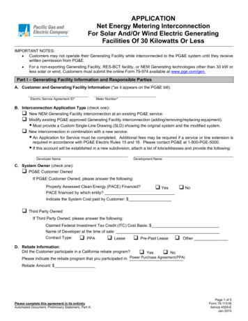
OH: ServicesGreenbookEMWPRequirements for Customer-Owned PolesVertical Clearance for Service Poles9. Conductors to service poles must have a minimum ground clearance as follows:A. Over the center portion of the street, 18’ 0” minimum. For conductor height over trolleys, railroad tracks,telephone lines, etc., consult PG&E.B. At the curb or outer limits of possible vehicular traffic, 16’ 0” minimum.C. Over private driveways, lanes, or other areas accessible to vehicles used for industrial, commercial, oragricultural purposes, 16’ 0” minimum.D. If required clearances cannot be obtained with a minimum-length service pole and the constructionsillustrated on Pages 7 through 9, the required clearances should be obtained by using a longer (taller)pole. The setting depth for a 25-foot and longer pole must be followed as specified in Table 3 on Page 3.10’ 0” Minimum (from surface of Company pole, lines, or equipment)Consult PG&E for Maximum Distance (see Note 21 on Page 5)Service Drop (see Note 21 on Page 5)See Note 9CPowerCompanyPole18’ 0” Min.(see Note 9A)16’ 0” Min.(see Note 9B)Street orRoad12’ 0”Min.12’ 0”Min.Figure 1Clearances for Service PolesSeeNote 22 onPage 6SidewalkService Entrance Conductors10. The customer must furnish, install, and maintain the service entrance wiring and service equipment beyondthe point of attachment to PG&E’s service wires. The service entrance wires must be continuous and must beof a size and type that will provide not less than the minimum standard of safety as specified in local city andcounty ordinances or, where there is no local ordinance, as specified in the current issue of the NationalElectrical Code (NEC).11. The neutral conductor of 2-wire, 120 V and 3-wire, 120/240 V (or 120/208 V) services must be securelyconnected to the neutral terminal of the meter socket and extended through to the neutral terminal of theservice entrance switch. It must be continuous (without splice) from the service head to the serviceentrance switch.12. At least 18 inches of service entrance conductors must be provided outside the service head.13. Weatherproof wire is not permitted in conduit.025055 Page 4 of 17Rev. #19:12 17 2020
OH: ServicesGreenbookEMWPRequirements for Customer-Owned PolesService Entrance and Load Side Conduit and Conduit Covering14. Service entrance and load side conduit and conduit covering requirements must comply with applicable codesand local requirements. G.O. 95 requires that any conduit installed below the 8-foot level on the pole must betreated as a riser; in which case, the conduit must be either rigid galvanized steel or 2-inch minimum diameterSchedule 40 PVC.Exception: Conduit that enters the top of an enclosure is considered to be “protected” by the enclosure and neednot be treated as a riser unless installed below the 6-foot level. Conduit installed above the 6-foot or 8-foot level(whichever height applies) must be either: (1) galvanized rigid steel conduit, (2) rigid aluminum conduit,(3) electrical metallic tubing, (4) IMC, or (5) PVC plastic conduit having a minimum wall thickness of 0.15 inches(Schedule 40 for 2-inch PVC conduit or larger, Schedule 80 for 1-1/2-inch or smaller). All fittings must be rain-tight.If PVC plastic conduit is used, it need not be covered. If rigid steel or other approved metallic conduit is used, itmust be enclosed with PVC “U” shaped molding for a minimum distance of 8 feet below the lowest open serviceentrance conductor. The covering must be fastened to the pole at intervals not greater than 3 feet (see Page 11).15. Wood Block:A. A wood block must be attached directly over the service head in the following situations:(1) On a service pole where electrical metallic tubing, rigid steel, or IMC is used.(2) On a wood pole with plastic conduit installation when the service head is metallic and the neutral serviceentrance conductor is not insulated.B. A wood block over the service head is not required in the following instances:(1) On a service pole with plastic conduit installation except as noted in Note 15, A. above.(2) On a metallic pole, provided the pole is effectively grounded and provided all metallic conduits areadequately bonded to the metal pole with approved clamps or connectors.C. Attach wood blocks as shown on Pages 8 through 10.16. All conduit and fittings must be rain-tight.17. Water pipe and fittings are not permitted for use as electrical conduit.Service Entrance Switch18. Main switch, receptacles, and other equipment on the load side of the meter must be of weatherproof designor protected by weatherproof enclosures. Such equipment must comply with local ordinances and must alsocomply with the California Building Standards Code - Electrical Regulations.19. The switch cover must be locked if the enclosure contains exposed live parts.Grounding20. The customer must be responsible for bonding and grounding all exposed, non-current-carrying metal parts.Grounding and bonding must be in accordance with NEC and local ordinances. PG&E prefers, but does notrequire, the grounding electrode conductor wire to be protected against physical damage by rigid steel conduitor armored cladding (see Pages 8 and 10 for additional details).Pole Location21. Poles must be located so that the vertical clearances specified in Note 9 and Figure 1 on Page 4 can beobtained. A service pole must not be located less than 10 feet from the surface of the PG&E pole, orpole-mounted equipment, or within 10 feet of the vertical plane of a PG&E line.PG&E must be consulted for maximum span lengths, as they can vary depending on wire type and size, loadingarea, clearances, and suitable guying. The maximum span length of PG&E’s service drop to a temporary polemust not exceed 100 feet, and if 4/0 conductor is necessary, not more than 80 feet. The maximum span length fora permanent type installation may vary from 80 feet to 150 feet upward depending on the variables mentioned.The pole must also be positioned so that the pole brand will not be hidden by the main service switch, metersocket box, or conduit runs.Rev. #19:12 17 2020025055 Page 5 of 17
OH: ServicesGreenbookEMWPRequirements for Customer-Owned PolesGuying or Bracing22. Where conductors cross a street or road, the customer’s pole must be guyed or braced against the pull ofconductors as follows:A. Temporary Poles: Anchor guy as shown in Figure 13 on Page 12, or with wood braces not smaller than 2” x 4”timber and securely bolted to the pole as per Figure 14 on Page 12. See Figure 2 on Page 8 for the correctplacement of guy or brace.B. Permanent Service Poles: Anchor guy only as shown in Figure 13 on Page 12. See Figure 5 on Page 10 forthe correct placement of guy.C. The guy strain insulator is to be located in a zone: 8 feet or more above the ground; and 8 feet or more belowthe level of the lowest supply conductor, or 6 feet or more from the surface of the pole and 1 foot or morebelow the level of the lowest supply conductor.Metering Requirements23. Meters must be furnished by PG&E. See Greenbook sections 5, 6, and 7 for meter panel and additionalmetering requirements.24. For residential installations, meter sockets without test bypass facilities must be furnished, installed, and wiredby the customer as shown on Page 12.25. For commercial and industrial applications, meter sockets with PG&E-approved test bypass facilities must befurnished, installed, and wired by the customer.26. Customer owned poles for residential use are limited to only one meter panel rated at 320 amps (continuous)or less. Poles for non residential applications are limited to only one meter panel rated at 200 amps or less.Installations with more than one meter panel or a meter panel with a greater ampacity must be installed onpanelboard construction as shown in Document 065374.Verifying Depth of Customer Owned PolesApplicants who plan to install a new customer owned service pole prior to inspection by PG&E personnel can usefollowing method for PG&E inspectors to verify the setting depth of newly installed poles that have already been set inthe ground. See notes below and Figure 18, “Pole Depth Verification”, on page 17. These installations will be approvedat the discretion of the PG&E Electrical inspector.27. Install 3/4 inch diameter PVC Schedule 40 conduit from the bottom of the pole to 12 inches above grade level.28. Place a removable cap on the top of the conduit and a permanent cap on the bottom of the conduit.29. Attach the conduit to the pole using three heavy duty pipe straps and 10D galvanized nails. Place one pipe straptowards the top of the conduit below the removable cap. Place the second strap in the middle of the conduit andthe third strap at the bottom of the conduit just above the permanent cap.30. Install a PG&E approved pole to, at least, the minimum required setting depth. Refer to Table 3 Pole SettingDepths on page 3.31. Ensure the PVC conduit is not broken and remains free of soil, equipment, or other obstacles, throughout theconduit. The conduit will be used to verify the pole setting depth.32. Backfill and compact the soil around the pole to 90% of maximum density. Determine the maximum density andthe in place density by the California Test Method No. 216 6, Parts I and II respectively, or by ASTM D 1556and D 1557 respectively. A copy of the test results may be required by PG&E.33. Call for inspection after the installation of the customer owned pole is complete.025055 Page 6 of 17Rev. #19:12 17 2020
OH: ServicesGreenbookEMWPRequirements for Customer-Owned PolesTable 5 Materials to Be Furnished and Installed by the CustomerItemDescription1 Pole, 6” x 6” Timber, Class 6 Round, or Equivalent Metal (length as required, see Note 2 on Page 1)Pole, Wood, or Equivalent Metal (see Note 6, Note 7, and Note 8 on Page 2). (See Table 1 on Page 3 for2approved list of wood pole suppliers.)3 Meter Socket, Main Service Switch4 Conduit, Service (see Note 14 on Page 5)5 Conduit, Load Side (see Note 14 on Page 5)6 Conduit Fitting, Threaded, With Cover and Gasket7 1 Covering, PVC Conduit, or PVC Moulding (see Page 9)8 1 Wood Block (4” x 4” x 6” or two 2” x 4” x 6” nailed together)9 Service Head10 Service Knob11 Wire, Insulated (size as required) (18” minimum extension from service head)12 Bolt, Machine, 5/8 or 3/4, (as required), Galvanized13 Washer, Curved, 3” x 3” (for 5/8” Bolt) or 4” x 4” (for 3/4” Bolt), Galvanized14 Guy Hook or Guy Pole Plate and Thimble Assembly15 Guy Strand Cable, 7/32” or 1/4“ Minimum Galvanized Steel or Equivalent16 Insulator, Guy Strain (10,000 lbs. minimum)17 Guy Grip, Preform, (as required)18 Anchor Rod, 5/8” x 6’ 0” Minimum, and Fittings (as required)19 Anchor, 16” Cross Plate, or 8” Expanding20 Guy Marker21 Push Brace, 2” x 4” Minimum Timber (securely bolted to pole). See Figure 14 on Page 12.22 Grounding by Customer (see Pages 8 and 10)1 Omit conduit covering, Item 7, and wood block, Item 8, on a metal pole or on a wood pole with plastic conduit (seeNote 15 on Page 5). Exception: The wood block is required for a wood pole with plastic conduit when theservice head is metallic and the neutral service entrance conductor is uninsulated (see Note 15 on Page 5).Table 6 Materials to Be Furnished and Installed by PG&EItemsDescription23Vertical Construction24Spool and Clevis25Meter, Watthour (as required)26Service Wire (as required)27Insulator, for Service Wire (as required)28Connectors, Service Sleeve (as required)29Preformed Grip, Dead-End (as required)Rev. #19:12 17 2020Document 022439 059626025202028852028851025055 Page 7 of 17
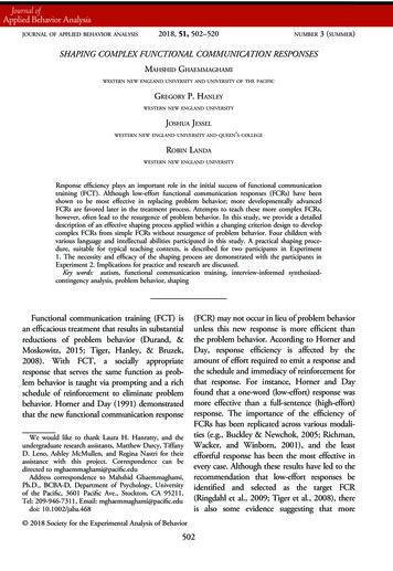
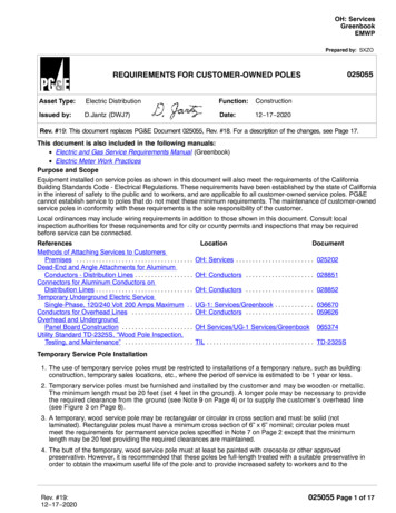
OH: ServicesGreenbookEMWPRequirements for Customer-Owned PolesTemporary InstallationsNotes1. Locate the guy in line with the service drop. The guy must be maintained taut.2. Grounding and bonding, by the customer, must be in accordance with NEC and local ordinances, (see Note 20 onPage 5). The ground rod must be located no less than 12 inches from the pole surface.3. Customer’s equipment must not be installed in the climbing space or over the pole brand. See Note 20 onPage 5 for grounding requirements.4. For customer-owned poles, span lengths are limited to 100 feet. The vertical separation between conductors invertical construction is 8 inches minimum.5. If the poles are to be set in firm soil, use the setting depths from the “Firm Soil” column of Table 3 on Page 3. Ifthe poles are to be set in rock, use the setting depths from “Rock” column of Table 3 on Page 3. If the poles areto be set in soft soil, the poles must be set deeper than the depths shown in Table 3. Consult the PG&E projectcoordinator for the other approved methods for soft soil.16” min.29278SeeTable 426PG&ELineSee Note 144 on Page 520’ 0” Minimum(see Note 2 on Page 1)3 See Note 325Meter12 ” Min.48”Min.Figure 2Service Drop Cable to Receptacles11 28Customer’sLine75See Note 144 on Page 525 Meter63 See Note 3117 See Note 217 See Note 2025055 Page 8 of 17PG&EInsulatedLine875” Max.66” Preferred48” Min.75” Max.66” Preferred48” Min.269117GroundLevel1028See Note 22.Con Page 6Figure 13 orFigure 14 onPage 122924 23SeeTable 49See Figure 15,Page 13 12 13 14 1715 16 or 20See AlternateLocations6” min.8 ” Min.20’ 0” Minimum(see Note 2 on Page 1)See AlternateLocationsGroundLevel48”Min.Figure 3Service Drop Cable to Overhead LineRev. #19:12 17 2020
Requirements for Customer-Owned PolesOH: ServicesGreenbookEMWPTemporary Installations (continued)PG&E Insulated Line6” Min.8”See Table 4Page 38”8”12” Min.Figure 4Open Insulated Wire Construction(For use when the load requires a larger service drop conductor)GuyServiceDropGuyAlternate Locations forService Drop and Guy(see Note 1 on Page 8)Detail ASee Figure 16 on Page 14Rev. #19:12 17 2020025055 Page 9 of 17
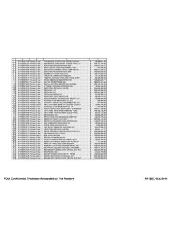
OH: ServicesGreenbookEMWPRequirements for Customer-Owned PolesPermanent InstallationsNotes25’ 0” Min.(see Note 7on Page 225’ 0” Min.(see Note 7on Page 21. Locate the guy in line with the service drop. The guy must be maintained taut.2. Grounding and bonding, by the customer, must be in accordance with NEC and local ordinances (see Note 20 onPage 5), The ground rod must be located no less than 12 inches from the pole surface.3. Customer’s equipment must not be installed in the climbing space or over the pole brand. See Note 20 on Page 5for grounding requirements.4. For customer-owned poles, span lengths are limited to 150 feet. The vertical separation between conductors invertical construction is 8 inches minimum.5. If the poles are to be set in firm soil, use the setting depths from the “Firm Soil” column of Table 3 on Page 3. Ifthe poles are to be set in rock, use the setting depths from “Rock” column of Table 3 on Page 3. If the poles areto be set in soft soil, the poles must be set deeper than the depths shown in Table 3 on Page 3. Consult thePG&E project coordinator for the other approved methods for soft soil.See Alternate2924 23See Alternate2626Locations296”Min.Locations27108” Min.PG&E6” Min.PG&EInsulatedLine8LineSee8SeeTable 49Table 49Figure 15,28Page 13112712 13 14 171112” minNote 22.Con Page 6Customer’s15 16Line4 See Note 14on Page 57See Note 14Figure 13 on74 on Page 5Page 123 See Note 35225 Meter25 Meter617See Note 24’ 6” Min.(see Table 3on Page 3)Figure 5Service Drop Cable to Underground Line025055 Page 10 of 17217 See Note 2GroundLevel5ToLoad675” Max.66” Preferred48” Min.75” Max.66” Preferred48” Min.GroundLevel3 See Note 34’ 6” Min.(see Table 3on Page 3)Figure 6Service Drop Cable to Overhead LineRev. #19:12 17 2020
OH: ServicesGreenbookEMWPRequirements for Customer-Owned PolesPermanent Installations (continued)6” min.PG&E Insulated Line8”GuyGuyAlternateLocations forService Dropand GuyServiceDropNote 4Page 10See Table 4Page 38”8”12”Guy(see Note 1on Page 10)Detail BSee Figure 5 and Figure 6 on Page 10Figure 7Open Insulated Wire Construction(for use when the load requires a larger service drop conductor)Method of Covering Metal Conduits and Attaching Coverings on Wood PolesNotes1. Strap PVC conduit to the pole with 2 hole heavy duty pipe straps or galvanized perforated plumber’s tapespaced not more than 3 feet apart (see Figure 8).2. Attach PVC molding to the poles with 1/4” x 2-1/2” galvanized washer-head lag screws.Figure 8PVC Conduit(see Note 1)Rev. #19:12 17 2020Figure 9PVC Molding(see Note 2)025055 Page 11 of 17
OH: ServicesGreenbookEMWPRequirements for Customer-Owned PolesMeter Connections1. For test bypass facilities, see Note 25 on Page 6.2. All wiring material on the load side of the meter socket must be in accordance with applicable electrical codes,city and county ordinances, and must comply with the California Building Standards Code ElectricalRegulations. Unless threaded connections are used, adequate bonding of all sections of the serviceequipment must be provided.Threaded Conduit Hub4-TerminalMeter Socket(see Note 1)ThreadedConduit Hub4-Terminal Meter Socket(see Note 1)8”Weatherproof ServiceSwitch. Cover Must BeLocked if Enclosure ContainsExposed Live Parts.LockGround Wire(see Note 20 on Page 5)Figure 10120/240 V, 3-WireWith WHM, ServiceSwitch, and Receptacle inWeatherproof Cabinet(see Note 2)Weatherproof Receptacles(see Notes 18 and 19 onPage 5)Figure 11120/240 V, 4-Wire DeltaWith Weatherproof ServiceSwitch and Receptacles(see Note 2)Figure 12120/240 V, 3-WireWith Weatherproof ServiceSwitch and Receptacles(see Note 2)Details of Anchors, Guying Materials, and Brace5/8” Diameter x 72”Galvanized SteelAnchor Rod(minimum size)2” x 4” Min. WoodBrace 20-FootLength Approx.6” Approx.17 18 19 20SteelAnchorBolted to Pole45 ServicePole4” x 4” Min.StakeBolted toStake36” Min.Figure 14Wood Brace(for use with temporary pole only)Figure 13Steel Anchor025055 Page 12 of 17Note: Use 1/2 Galvanized MachineBolts, and 1” x 1” Diameter CurvedWashers to attach wood brace tostake and pole.Rev. #19:12 17 2020
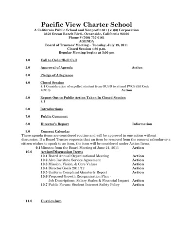
Requirements for Customer-Owned Poles1312OH: ServicesGreenbookEMWP141715Figure 15Guying MaterialsTemporary Commercial Service to Non-Substantial Portable StructureNotes1. Temporary Service AttachmentTemporary services will not be directly attached to any structure considered by PG&E to be of inadequatestrength. The structure must, in all cases, be substantial (see Note 2) and capable of supporting the servicespan, as well as the force of the ladder and worker against the service mast.2. Portable Buildings (Figure 16 on Page 14 and Figure 17 on Page 16)Portable buildings, such as small sheds, combined office/toilet structures, etc., are not considered to besubstantial structures unless they are staked in place in the manner shown in Figure 17 on Page 16.Furthermore, periscopes must be installed and adequately braced in accordance with Figure 17 on Page 16 andthe “Electric Service: Overhead” Section of the Electric and Gas Service Requirements Manual (Greenbook).3. Temporary Poles (Figure 16 on Page 14)Customer-owned temporary poles are required for support of PG&E’s overhead service wires if the temporarybuilding to be served is considered by PG&E as not substantial.4. Method of ServingNon-substantial structures that have been approved for the attachment of metering equipment and serviceperiscopes may be served in the manner shown on Page 14. However, if desired, the metering equipment may beremoved from the structure and placed on the temporary pole as shown in Figure 2 on Page 8.5. The distance from the centerline of the periscope service mast to the pole face must not exceed 24 inches.6. A portable structure must not obstruct the climbing space of a temporary pole.7. The working space in front of the meter must not be obstructed.8. The minimum distance from the surface of a PG&E pole to a customer’s pole is 10 feet.9. The maximum permitted span to a PG&E pole is 100 feet and may be only 80 feet in some cases (seeNote 21 on Page 5).Rev. #19:12 17 2020025055 Page 13 of 17
OH: ServicesGreenbookEMWPRequirements for Customer-Owned PolesTemporary Commercial Service to Non-Substantial Portable Structure (continued)10 Feet Minimum (see Note 8 on Page 13)100 Feet Maximum (see Note 9 on Page 13)PG&E PoleCustomer’s Pole(see Note 6 on Page 11)PG&E LineCustomer’s Portable BuildingGuy36” x 36” Working Space(see Note 7 on Page 11)24” Maximum(see Note 5 on Page 13)Customer’s Temporary Pole(for details, se
A. An 11-gauge steel pole with 8-1/2-inch minimum diameter at ground line, set directly in the ground. B. A 7-gauge steel pole with 7-inch minimum diameter at ground line, set directly in the ground. C. A 5-inch extra-strong steel pipe (Schedule 80) set in concrete to obtain equivalent bearing surface. D.