Transcription
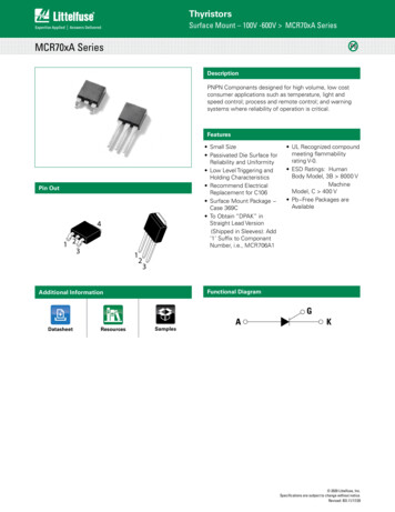
ThyristorsSurface Mount – 600V MAC4DHMMAC4DHMPbDescriptionThe MAC4DHM is designed for high volume, low cost,industrial and consumer applications such as motor control;process control; temperature, light and speed control.Features Small Size Surface MountDPAK Package Passivated Die forReliability and Uniformity Four Quadrant Triggering Blocking Voltage to 600 V On State Current Ratingof 4.0 A RMS at 93 C Low Level Triggering andHolding CharacteristicsPin Out Epoxy Meets UL 94 V 0@ 0.125 in ESD Ratings: HumanBody Model, 3B 8000 VMachine Model, C 400V Lead Free Packages areAvailableFunctional Diagram441 23MT 2MT 1G123 2020 Littelfuse, Inc.Specifications are subject to change without notice.Revised: 09/01/20
ThyristorsSurface Mount – 600V MAC4DHMMaximum Ratings (TJ 25 C unless otherwise noted)RatingSymbolValueUnitPeak Repetitive Off-State Voltage (Note 1)(Gate Open, Sine Wave 50 to 60 Hz, TJ -40 to 110 C)VDRM,VRRM600VOn-State RMS Current (Full Cycle Sine Wave, 60 Hz, TC 93 C)IT4.0A(RMS)Peak Non-Repetitive Surge Current(One Full Cycle Sine Wave, 60 Hz, TC 110 C)ITSM40ACircuit Fusing Consideration (t 8.3 msec)2It6.6A²secPeak Gate Current (Pulse Width 20 µsec, TC 108 C)IGM4.0APeak Gate Power (Pulse Width 10 µsec, TC 108 C)PGM2.0WPeak Gate Voltage (Pulse Width 20 µsec, CT 93 C)VGM5.0VAverage Gate Power (t 8.3 msec, TC 108 C)PG(AV)1.0WOperating Junction Temperature RangeTJ-40 to 110 CStorage Temperature RangeTstg-40 to 150 CStresses exceeding Maximum Ratings may damage the device. Maximum Ratings are stress ratings only. Functional operation above the Recommended Operating Conditions is not implied. Extended exposure to stresses above theRecommended Operating Conditions may affect device reliability.1. VDRM and VRRM for all types can be applied on a continuous basis. Ratings apply for zero or negative gate voltage; however, positive gate voltage shall not be applied concurrent with negative potential on the anode. Blocking voltagesshall not be tested with a constant current source such that the voltage ratings of the devices are exceeded.Thermal CharacteristicsRatingJunction to Case (AC)Junction to AmbientJunction to Ambient (Note 2)Thermal Resistance,Maximum Lead Temperature for Soldering Purposes, 1/8” from case for10 secondsSymbolValueUnitRƟJCRƟJARƟJA3.58880 C/WTL260 C2. These ratings are applicable when surface mounted on the minimum pad sizes recommended.3. 1/8" from case for 10 seconds.Electrical Characteristics - OFF (TJ 25 C unless otherwise noted ; Electricals apply in both directions)CharacteristicTJ 25 CTJ 110 CPeak Repetitive Blocking Current(VD VDRM VRRM; Gate trical Characteristics - ON (TJ 25 C unless otherwise noted; Electricals apply in both directions)CharacteristicPeak On State Voltage (Note 4) (ITM 6.0 A)MT2( ), G( )MT2( ), G( )TypMaxUnit 1.31.6V1.85.0IGTMT2(–), G( )Holding Current (VD 12 V, Gate Open, Initiating Current 200 mA))Gate Non Trigger Voltage (Continuous dc) (VD 12 V, RL 100 Ω, TJ 110 C)All Four Quadrants(VD 12 V, IG 5.0 mA)2.15.02.45.04.210-1.515mAVGD0.10.4-VMT2( ), G( ) 1.7510MT2( ), G( ) 5.210(VD 12 V, IG 5.0 mA)MT2( ), G( ) 2.110ILMT2(–), G( ) 2.210MT2( ), G( )0.50.621.3MT2( ), G( )MT2( ), G( )MT2(–), G( )mAIH(VD 12 V, IG 5.0 mA)(VD 12 V, IG 10 mA)Gate Trigger Voltage(Continuous dc)(VD 12 V, RL 100 Ω)MinVTMMT2( ), G( )Gate Trigger Current(Continuous dc)(VD 12 V, RL 100 Ω)Latching . Indicates Pulse Test: Pulse Width 2.0 ms, Duty Cycle 2%. 2020 Littelfuse, Inc.Specifications are subject to change without notice.Revised: 09/01/20
ThyristorsSurface Mount – 600V MAC4DHMDynamic CharacteristicsCharacteristicRate of Change of Commutating Current(VD 200 V, ITM 1.8 A, Commutating dv/dt 1.0 V/µsec,TJ 110 C, f 250 Hz, CL 5.0 µfd, LL 80 mH, RS 56 Q,CS 0.03 µfd) With snubber see Figure 11Critical Rate of Rise of Off-State Voltage(VD 0.67 x VDRM, Exponential Waveform, Gate Open, TJ 110 C)SymbolMinTypMaxUnit(dI/dt)c-3.0 A/msdV/dt20- V/µsVoltage Current Characteristic of SCRSymbolParameterVDRMPeak Repetitive Forward Off State VoltageIDRMPeak Forward Blocking CurrentVRRMPeak Repetitive Reverse Off State VoltageIRRMPeak Reverse Blocking CurrentVTMMaximum On State VoltageIH CurrentVTMOn StateIRRM at VRRMQuadrant 1Main Terminal 2 IHHolding CurrentIHQuadrant Definitions for a TriacQuadrant 3Main Terminal 2-Off State VoltageIDRM at VDRMVTMMT2 Positive(Positive Half Cycle) ( ) MT 2Quadrant II(-) IGTGate( ) MT 2( ) IGTGateQuadrant IMT 1MT 1REFREF(-) MT 2(-) MT 2IGTQuadrant III (-) IGTGate( ) IGTGateQuadrant IVMT 1REFIGTMT 1REFMT2 Negative(Negative Half Cycle)All Polarities are referenced to MT1.With in-phase signals (using standard AC lines) quadrants I and III are used 2020 Littelfuse, Inc.Specifications are subject to change without notice.Revised: 09/01/20
ThyristorsSurface Mount – 600V MAC4DHMFigure 2. On-State Power DissipationFigure 3. On State CharacteristicsFigure 4. Transient Thermal Responser(t), TRANSIEN T RESIST ANCE (NORMALIZED)Figure 1. Typical RMS Current Derating1.00.1Z JC(t) R JC(t) r(t)0.010.11.010100100010 Kt, TIME (ms)Figure 5. Typical Gate Trigger Current vs, Junction TemperatureFigure 6. Typical Gate Trigger Voltage vs. Junction Temperature 2020 Littelfuse, Inc.Specifications are subject to change without notice.Revised: 09/01/20
ThyristorsSurface Mount – 600V MAC4DHMFigure 7. Typical Holding Current vs. Junction TemperatureFigure 8. Typical Latching Current vs.Junction Temperature12IL, LATCHING CURRENT (mA)IH , HOLDING CURRENT (mA)5.04.03.0MT2 NEGATIVE2.0MT2 POSITIVE1.00-40-10358065108.0Q26.04.0Q42.0 Q1Q3-0-40110T , JUNCTION TEMPERA TURE ( C)Figure 9. Exponential Static dv/dt vs.Gate MT1 Resistance, MT2( )10203550658095110TJ , JUNCTION TEMPERA TURE ( C)Figure 10. Exponential Static dv/dt vs.Gate MT1 Resistance, MT2(-)40VD 400VTJ 110 CSTATIC dv/dt (V/ s)353025MAC4DHM2015105100100010 KGATE-MT1 RESIST ANCE (OHMS)Figure 11. Simplified Test Circuit to Measure the Critical Rate of Rise of Commutating Current (di/dt)LL200VRMSADJUST FORITM, 60 Hz VAC1N4007CHARGETRIGGERCHARGECONTROLCLTRIGGER CONTROLMEASUREIRSCSMT21N914 51G-ADJUST FOR di/dt(c)200VMT1Note: Component values are for verification of rated (di/dt)c. See AN1048 for additional information. 2020 Littelfuse, Inc.Specifications are subject to change without notice.Revised: 09/01/20
ThyristorsSurface Mount – 600V MAC4DHMDimensionsSoldering FootprintAEb3B6.200.244c24L3D12L4CAb2ZDetail AH35.800.228NOTE 7ecBottom ViewSide ViewbTop ViewZ0.005 (0).13M2.580.1023.000.118CBottom LANEL2C SeatingPlaneLSCALE 3: 1mminchesA1L1Detail ARotated 90 C DIMENSIONING AND TOLERANCING PER ANSI Y14.5M,1982.CONTROLLING DIMENSION: INCH. STYLE 6: PIN 1. MT1MT2GATEMT2 2020 Littelfuse, Inc.Specifications are subject to change without notice.Revised: 09/01/20
ThyristorsSurface Mount – 600V MAC4DHMDimensionsPart Marking System4DPAK-3Case 369D-01Issue B1 2TO251-3L MaxA0.2130.2245.405.70B0.2520.2606.406.60Pin Assignment1Main Terminal 12Main Terminal 260.550.65F0.0230.0310.580.091 500.0651.35SZ0.063 TYP.0.0530.150 TYP.DIMENSIONING AND TOLERANCING PER ANSI Y14.5M, 1982.CONTROLLING DIMENSION: INCH. STYLE 6: PIN 1. MT1MT2GATEMT2GateMain Terminal 22.30 TYP.HV Device Code D, M, or N Year Month Assembly Site Lot Serial Code Pb-Free PackageTMillimetersMaxAC4DHMGYMAXX3D3PL0.13 (0.0005)MinG1.2.3.4.5.2FHDim1DPAK-3Case 369DStyle 6KGAC4DHMGYMAXX3CSDPAK-3Case 369CStyle 61.60 TYP1.653.80 TYP.Ordering InformationDevicePackage TypePackageShippingMAC4DHM 001DPAK 3369D4000 Units / BoxMAC4DHM 001GDPAK 3(Pb Free)369D4000 Units / BoxMAC4DHMT4DPAK 3369C2500 / Tape & ReelMAC4DHMT4GDPAK 3(Pb Free)369C2500 / Tape & ReelDisclaimer Notice - Information furnished is believed to be accurate and reliable. However, users should independently evaluate the suitability of and test each product selected for their own applications. Littelfuse products arenot designed for, and may not be used in, all applications. Read complete Disclaimer Notice at: www.littelfuse.com/disclaimer-electronics 2020 Littelfuse, Inc.Specifications are subject to change without notice.Revised: 09/01/20
2020 Littelfuse, Inc. Specifications are subject to change without notice. Revised: 09/01/20 Thyristors Surface Mount - 600V MAC4DHM Figure 3.