Transcription
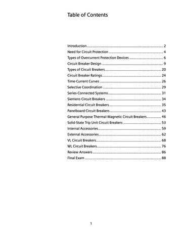
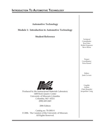
Application NoteAutomotive Circuit Protection usingLittelfuse Automotive TVS DiodesThe ChallengeThe designers of automotive electronics face many technical challenges during the system design process, including designingmethods of protection against a variety of electrical hazards. The three major sources of electrical hazards in these systems areelectrostatic discharge (ESD), lightning, and switching loads in power electronics circuits. Overcoming transient surges that can harmthe vehicle’s electronics is one of the biggest challenges of the design process.The SolutionProtecting automotive electronics includes eliminating transient surges that can damage the control units, infotainment electronics,sensors, fuel injectors, valves, motors, 12/24/42/48 volts powertrains, and hydrolytic controllers, etc.Note: For 48V power system with high power surge rating, welcome to contact Littelfuse for technical support and application test)What do Littelfuse Transient Voltage Suppression (TVS) Diodes Protect?As shown in Figure 1, Littelfuse TVS diodes provide protection for four main categories of vehicle systems: safety, performance andemissions, comfort and convenience, and hybrid vehicles.In modern automotive designs, all on-board electronics are connected to the battery and the alternator. As indicated in Figure 2, theoutput of the alternator is unstable and requires further conditioning before it can be used to power the vehicle’s other systems.Currently, most of the alternators have zener diodes to protect against load dump surges; however, these are still not sufficient. Duringthe powering or switching of inductive loads, the battery is disconnected, so that unwanted spikes or transients are generated. If leftuncorrected, these transients would be transmitted along the power line, causing individual electronics and sensors to malfunction orpermanently damaging the vehicle’s electronic system, affecting overall reliability.Figure 1. Vehicle Systems Subject to Transient Surge HazardsSafetyComfort and ConvenienceHID LightingSeating Controls/MemoryRide ControlTheater LightingClimate ControlNavigation SystemsInfotainment/VideoAirbagsBattery DisconnectAnti-rolloverStability ControlSeat Belt Pre-tensioningTire Pressure MonitoringHybrid VehiclesPerformance and EmissionsEngine ManagementAdaptable SuspensionAdvanced PowertrainsGas ElectricFuel Cell ElectricDiesel ElectricLi-Ion PolymerUltra-capacitorsLittelfuse.com1 2019 Littelfuse Inc.
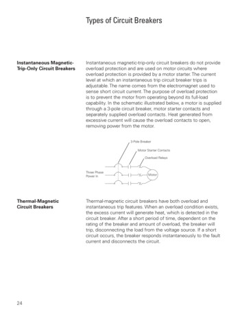
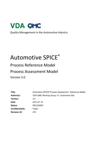
Application NoteAutomotive Transient Surge (Not ESD) StandardLittelfuse is a leading provider of TPSMF4L, TPSMB, TPSMA6L, TPSMC, TPSMD, TP6KE, TP1.5KE, TP5KP, SZSMF, SZ1SMA, SZ1SMB,SZP6SMB, SZ1SMC, SZ1.5SMC, SLD, SLD5S, SLD6S, and SLD8S Series. TVS Diodes which can provide secondary transient voltageprotection for sensitive electronics from transients induced by load dump and other transient voltage events. These series offersuperior electrical performance in a small footprint package, allowing designers to upgrade their circuit protection without altering theirexisting design footprint or to provide more robust protection in new circuit layouts.Load dump protection requires high energy TVS diodes in the 12 and 24 volt system. For more information on load dumpprotection, visit Littelfuse.com.The automotive market has major two standards that outline protection against transient surges: JASO and ISO7637-2 (Surge) test forthe Japanese, American, and international markets. JASO A-1 outlines test conditions for 14 volt vehicle systems; JASO D-1 outlinestest conditions for 27 volt vehicles.The following test standards are international and American test standards, which include the load dump, switching transientsand ESD threats.Figure 2. The Alternator Causes Most of the Transients In a Vehicle’s Electrical SystemAlternator/Regulator Assembly(Actual circuit is fully wave rectified)WipersAirbagABS BATTVoltageReg.EECWindow MotorInternational Standard ISO7637-2:USA National Standard: Applies to road vehicles-electrical disturbance by conductionand coupling SAE (Society of Automotive Engineers) J1113 GM 9105, ES-F2af-1316-AA Ford (Visteon)More Information on the ISO7637-2 Pulses: Refers to the unwanted transients in the switching events Automotive EMC Transition Requirements Pulse 4 - Starter crank – refers battery voltage drop during Pulse 1- Interruption of inductive load – refers tomotor start. This always happens in cold weatherdisconnection of the power supply from an inductive loadwhile the device under test (DUT) is in parallel with theinductive load Pulse 5 - Load dump – refers to the disconnection of thevehicle battery from the alternator while the battery isbeing charged. Pulse 2 - Interruption of series inductive load – refers to theinterruption of current and causes load switching Pulse 6 - Ignition coil interruption Pulse 3 - Switching spikes Pulse 7 - Alternator field decayPulse 1, 2, 3a, 3b, 5 - Relatedto high voltage transient getting into the supply line; Pulse4 defines minimum battery voltage. Refer to Figure 3aand Table 1 3a negative transient burst 3b positive transient burstFigure 3a: Surge Wave of Different Pulses & Its Magnitude120V Load Dump85V NoiseNominal14V24V Jump Start6V CrankReverseBatteryLittelfuse.com2 2020 Littelfuse Inc.
Application NoteAutomotive Environment Test Levels Pulse 1 is a transient caused by battery supply disconnectionfrom inductive loads.Table 1: ISO7637-2 Test Levels on Each Pulse (12 Volts)Test Levels (12V System)TestPulseI Min.IIIIIIV Max.Min. No. of Pulsesor Test Time1--–75V–100V5000 pulses Pulse 2a simulates transients due to sudden interruption ofcurrents in a device connected in parallel with the DUT due tothe inductance of the wiring harness.2a-- 37V 112V5000 pulses2b-- 10V 10V10 pulses3a--–112V–220V1 hour3b-- 75V 150V1 hour5a-- 65V 87V1 pulse Pulse 3a and 3b are switching transients.5b-- 65V 87V1 pulse Pulse 5a and 5b are load dump transients. 5b clamp voltageUs* is defined by different car manufacturers.Table 2: ISO7637-2 Test Levels on Each Pulse (24 Volts) The former levels I and II were deleted because they do notensure sufficient immunity in road vehicles.Test Levels (24V System)TestPulseI Min.IIIIIIV Max.Min. No. of Pulsesor Test Time1--–300V–600V5000 pulses2a-- 37V 112V5000 pulses Pulse 2b simulates transients from DC motors acting asgenerators after the ignition is switched off. Four performance levels for each pulse Different o/c voltage2b-- 20V 20V10 pulses Negative and positive3a--–150V–300V1 hour3b-- 150V 300V1 hour Pulse duration 0.1 - 400msSingle and burst5a-- 123V 173V1 pulse 5b-- 123V173V1 pulse TVS protection and its operation modeResults of Littelfuse Automotive TVS Diode in ISO7637-2 Surge TestTable 1a & 1b summarizes the compliance of each level of the ISO7637-2 surge test in 12 and 24 volt power systems when usingvarious Littelfuse Automotive TVS Diode series. Series TPSMF4L, TPSMA6L, TPSMB, TP6KE, TPSMC, TPSMD, SZSMF, SZ1SMA,SZ1SMB, SZP6SMB, SZ1SMC and SZ1.5SMC feature pulse power ratings from 400W to 3000W. TP6KE series is a through-hole TVSwhile the rest are surface mount. These devices help the power system pass the different surge tests (1, 2a, 2b, 3a, 3b, 5a and 5b)operationally as specified by ISO7637-2. Referred to the table 12 volt system below, only if the alternator Ri value is higher than 4.5Ω,TPSMD series TVS can then be used to pass the higher energy 5a surge. If Ri value (Altenator internal resistance) is lower than 4.5Ω,then the higher power TVS such as SLD, SLD5S, SLD6S or SLD8S series are suggested used for such design. For the 24 volt car powersystem surge compliance, refer to the 24 volt system results below.Table 1a: Littelfuse Automotive TVS Diode Series Compliance with Various Surge Levels in 12 & 24 volt Powertrains12V SystemTVS SeriesLevel 3Level 412a2b3a3b5a12a2b3a3b5a–75V 37V 10V–112V 75V 65V–100V 112V 10V–220V 150V 87VTPSMF4L/ MA6L/ SMB/ SZ1SMB / PSMC/ SZ1SMC / ssPassLittelfuse.com3 2020 Littelfuse Inc.
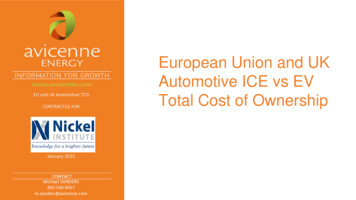
Application NoteTable 1b: Littelfuse Automotive TVS Diode Series Compliance with Various Surge Levels in 24 volt Powertrains24 Volt SystemTVS SeriesLevel 3Level 412a2b3a3b5a12a2b–300V 37V 20V–150V 150V 123V3a3bTPSMF4L/ MA6L/ SMB/ SZ1SMB / PSMC/ SZ1SMC / sPassPassPassConditional PassPassPassPassPassPassConditional al PassPassPassPassPassPassConditional Pass–600V 112V 20V –300V 300V5a 173VFigure 3b: TVS Diode Used as a Shunt/TransientSurge Protector for Various Car VBatteryECU, Airbag,Motor,Infotainment,etc.As shown in Figure 3b, the TVS diode TPSMA6L15A is placed before the ECU, sensors, airbag controllers, motor, etc. When thealternator provides power to the electronics, the TVS diode will protect against unwanted transients while allowing DC operatingvoltage of 12 - 14 volts to the electronic systems.Automotive Bus ProtectionThe most popular communication bus standards currently are the CAN and LIN buses.CAN bus (Control Area Network) is a vehicle bus standard designed to allow microcontrollers and devices to communicate with eachother within a vehicle with no need for a host computer.CAN bus is a message-based protocol, designed specifically for automotive applications but now also used in other areas, such asaerospace, industrial automation, and medical equipment.The popular high-speed CAN bus protocol is ISO11898-2, where this differential protocol is good for high-speed (1.0 Mbps) andmedium-speed (125Kbps) applications in harsh environmentsThe ISO11898-2 bus consists of the CAN H and CAN L data lines and a common ground signal. It has 12 and 24 volt systems withdifferent bus voltages.The LIN (Local Interconnect Network) bus standard is a serial network protocol used for communication between components invehicles. As the technologies and the facilities implemented in vehicles grew, a need arose for a cheap serial network because theCAN bus was too expensive to implement for every component in the car. European car manufacturers started using different serialcommunication topologies, which led to compatibility problems.The first fully implemented version of the new LIN specification (LIN version 1.3) was published in November 2002. In September2003, version 2.0 was introduced to expand its capabilities and provide for additional diagnostics features. LIN may also be used overthe vehicle’s battery power-line with a special DC-LIN transceiver, which is common in today’s automotive world.Littelfuse.com4 2020 Littelfuse Inc.
Application NoteTable 2: High-Speed CAN SpecificationsParameterPhysical Layer SpecificationFeaturesPopular ApplicationsTransmission SpeedCableTermination ResistanceMin/Max Bus VoltageMin/Max CommonMode Bus VoltageTable 3: LIN Bus ApplicationsHigh-Speed CANApplication SegmentsISO 11898-2RoofHigh speed differential bus,good noise immunityAutomotive and industrial controls1.0 Mbits/s @ 40 meters125 kbits/s @ 500 metersTwisted or parallel pair wires,shielded or unshielded cable120 W resistors located at each end of the bus12 V System: –3.0/ 16 V24 V System: –3.0/ 32 VCAN L: –2.0 (min)/ 2.5 V (nom)CAN H: 2.5 (nom)/ 7.0 V (max)Steering WheelSpecific LIN Application ExamplesSeatSensor, light sensor, light control, sun roofCruise control, wiper, turning light,climate control, radioSeat position motors, occupant sensors, control panelEngineSensors, small motorsClimateSmall motors, control panelMirror, central ECU, mirror switch, window lift,seat control switch, door lockDoorDifferences between CAN and LIN Bus ApplicationsControl Area Network (CAN) systems handle everything from power steering to the critical drive-train communications between theengine computer and the transmission. Local Interconnect Network (LIN) systems handle simple electromechanical functions, such asmoving the power seats and toggling the cruise control.Threats to CAN/LIN Busses in the Automotive WorldBecause CAN/LIN busses are two-wire communication busses for various control and monitor functions inside the car, they havea high chance of getting surges into the two wires and causing failure on the CAN/LIN transceivers. The following are protectionmethods for these two buses.Figure 4: CAN Bus ProtectionTxHostControllerRxRefCANTransceiverCAN HCAN LCommonModeChokeCAN BusCAN Bus Protection SchemeAs shown in Figure 4, the TPSMB30CA TVS diode is designed to protect the two CAN bus lines in common-mode (with 24 voltsystem) from the surge events. TPSMB24CA is a 600 watt bi-directional TVS diode with 25.6 volt reverse standoff voltage and 41.4volt maximum clamping voltage. It is ideal for protecting the CAN bus without clipping the CAN signals. In a 12 volt CAN system, twoTPSMB15CA TVS diodes are used instead of the TPSMB24CA.Figure 5 : LIN Bus ProtectionLIN BusLINTransceiverLIN NodeConnectLIN Bus Protection SchemeA LIN transceiver has signal ranges from 24 /–15 volts and data rate of 2.4 kbps to 20 kbps. As seen in Figure 5, it needs abidirectional asymmetrical TVS configuration to protect the two wires in a differential mode.TPSMA6L24A/TPSMA6L15A TVS dioes are connected in anti in-series mode to protect the two wires from surge events. The TPSMA6LTVS diode is a 600 watt device housed in a small DO-221AC package. An alternative solution with same power handling capabilitywould be to add a TPSMB30CA (bi-directional) to protect the LIN bus.Littelfuse.com5 2020 Littelfuse Inc.
Application NoteAutomotive Standard ISO16750-2 Vs. ISO7637-2 for Pulse 5 (Load Dump Surge Test)Littelfuse TVS products in ISO16750-2ISO 16750-2 was prepared by Technical Committee ISO/TC 22, Road vehicles, Subcommittee SC 3, Electrical and electronic equipment.In 2010, ISO16750 replace ISO7637 for load dump pulse 5a and 5b portion. Here we will list these two standard difference and give aguideline for load dump protection component selection.Load dumpThis test is a simulation of load dump transient occurring in the event of a discharged battery being disconnected while the alternator isgenerating charging current to other loads remaining on the alternator circuit.Based on below 2 waveforms definitions, we can see there is a difference between the tr rising slope. ISO16750 defines the risingslope from 10% (US-UA) to 90% (US-UA), while ISO7637-2 defines the rising slope from 10% US to 90% US.Figure 6: Pulse 5a Waveform in ISO16750-2Figure 7: Pulse 5a Waveform in ISO7637-2UtdUtdtrtrUS0,9 (US-U)A0,9 USUS0,1 (US-U)AUA0 0,1 USUA0t t timeU test voltagetd duration of pulsetr rising slope UA supply voltage for generatorin operation (see ISO 16750-2)US supply voltagett timeU test voltagetd duration of pulsetr rising slope UA supply voltage for generatorin operation (see ISO 7637-2) US supply voltage (Does notinclude UA)Base on above waveform definition, we can see there is a slight difference between the rising slope tr for pulse 5b US and US* inISO16750-2 and ISO7637-2.Figure 8. Pulse 5b Waveform in ISO16750-2Figure 9. Pulse 5b Waveform in ISO7637-2UtdUtdtrtrUS0,9(US-U)Aa0,9 USbUS0,1(US-U)AUAUA0 t timeU test voltagetd duration of pulsetr rising slopeUS supply voltageLittelfuse.comUSU S* UA supply voltage for generatorin operation (see ISO 16750-2) US* supply voltage with loaddump surpression0,1 US0t6* t timeU test voltagetd duration of pulsetr rising slope UA supply voltage for generatorin operation (see ISO 16750-2)t US supply voltage (Does notinclude UA) US* supply voltage with loaddump surpression (not includeUA) 2020 Littelfuse Inc.
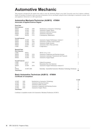
Application NoteOne important point here is how to choose a suitable TVS diode to pass ISO-16750-2 5b test for automotive electronics designer. Aswe have already known that ISO-16750-2 Pulse 5b (here we call it as 5b pulses, in short) is a clamped load dump surge by alternatorintegrated TVS diode, so other electrical or electronic components’ maximum voltage need be designed base on this US* clampedvoltage. In some cases, electronics designers may think that the centralized integrated TVS diode clamp voltage US* is still too highfor proper protection for the afterwards components. That means a lower clamp voltage TVS diode is needed for such protections.However, with such lower clamp voltage, centralized integrated TVS will be by-passed (or shorted) without dissipating any load dumpenergy. As a result, all load dump energy will be dissipated on the lower clamp voltage TVS diode. However, this waveform or surgeenergy level is now actually a ISO16750-2 5a (without centralized load dump protection) but not that of from 5b. Thus automotiveelectronics designers need to consider the rating of Us, Ri and td together to determine how high power the clamp TVS diode shouldtake. In this case, normally higher energy SLD/SLD5S/SLD6S/SLD8S series TVS diodes need be considered.If US* voltage is within TVS diode protection voltage range, then designer just need to select a small power TVS with working voltagea little bit higher than the US*, like TPMSB, TPSMC, TPSMD, SZ1SMB, SZP6SMB, SZ1SMC and SZ1.5SMC to withstand such 5b pulseenergy. At the same time, these TVS diode(s) can also able to withstand pulse1, 2a, 3a and 3b other impulses. For detail selection ofright TVS diode(s), please refer to below Figure 10 & 11 for 12 and 24 volt system.The rule for ISO16750 5b US* and TVS Vbr correlation refer to below SOA (Safe Operation Area) curve.Figure 10. 12v 5b Vbr vs. US*Figure 11. 24v 5b Vbr vs. US*Table 4. Pulse Parameter Difference Comparison Between ISO16750-2 & ISO7637-2ISO16750-2ParameterUN 12VUN 24VISO7637-2Min TestRequirementsUN 12VUN 24VUS(V)79 US 101151 US 202v65 US 87123 US 174vUS*(V)3565define by userdefine by userUA(V)1428Ri(ohm)0.5 Ri 41 Ri 8td(ms)40 td 400100 td 350tr(ms)10 0/-510 0/-5Ri 10 pulses at intervalsof1 minute13 1426 280.5 Ri 41 Ri 840 td 400100 td 35010 0/-510 0/-5Min TestRequirements1 pulse10 x Unom x Nact0.8 x Irated x 12000min -1Note - Ri is defined as the Alternator internal resistanceUnom: Specified voltage of the alternatorIrated: Specified current at an alternator speed of 6000 min - 1 (as given in ISO 8854)Nact: Actual alternator speed, in reciprocal minutes.For example, a traditional small passenger car with alternator 14 volts & 60 amps, its Ri at Nact 3000min-1 is 10 x 14 x 3000 / (0.8 x 60x 12000), it is about 0.73 ohm.Littelfuse.com7 2020 Littelfuse Inc.
Application NoteMajor Differences:ISO16750-2 defines 10 pulses in 10 minutes with 1 minute interval, while the old ISO7637-2 standard defines only 1 pulse. Thus, theprotector must have a higher reliability for this load dump protection in this new requirement.As seen in Figure 12 & 13 below, we use typical 12 and 24 volt AEC-Q101 qualified TVS for load dump pulse 5a test verification andcomparison between ISO16750-2 and ISO7637-2.Below is typical open load dump waveform for 12 and 24 volt system.Figure 12. 12v System 101v 400mS PulseFigure 13. 24v System 202v 350mS PulseIn Figure 14 & 15 below, we have a comparison test of ISO16750-2 and ISO7637-2 with different pulses duration in the 12V system.For the supply voltage Us 65 to 87 volt range, the Ri resistance required to withstand different pulses (40, 220 and 400 milliseconds) isat least more than 1.14 ohm in the ISO7637-2. The upper region of the Figure 14 & 15 is the safe operation area of SLD15U-017 device.Thus, we have to ensure the resultant resistance ( Alternator source impedance ) on the line exceeding 1.14 ohm to provide sufficientprotection for ISO7637-2 pulses. But, in the case of the Figure 15 with ISO16750-2 test requirement, the minimum resistance requiredon the line is 1.5ohm which is more than that of the ISO7637-2.Note: SLD15U-017 is a uni-directional TVS diode with 2200W power rating and a reverse standoff voltage 15V and a minimum breakdown voltage 16.7V.Figure 14. 12v System Single Pulse(ISO7637-2) US Vs. RiFigure 15. 12v System 10 Pulses(ISO16750-2) US Vs. RiSLD15U-017SLD15U-0171.21.1Ri (ohm)Ri (ohm)10.90.840mS 1 pulse0.7220mS 1 pulse0.6400mS 1 pulse0.56570.57681.58740mS 10 pulse220mS 10 pulse400mS 10 pulse79Us(v)84.59095.5101Us(v)*Note: Each curve above is SOA(Safe Operation 5*Note: Each curve above is SOA(Safe Operation Area).8 2020 Littelfuse Inc.
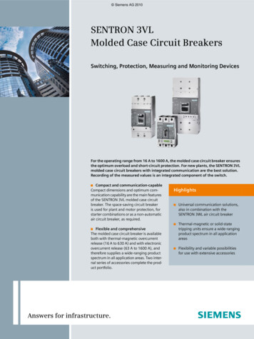
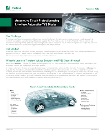
Application NoteIn Figure 16 & 17 below, we have a comparison test of ISO16750-2 and ISO7637-2 with different pulses duration in the 24 volt system.For the Supply voltage Us 123 to 174 volt range, the Ri resistance required to withstand different pulses (40mS, 220mS & 400mS) isat least more than 4.3 ohm in the ISO7637-2. The upper region of the Figure 16 & 17 is the safe operation area of SLD33-018 device.Thus, we have to ensure the resultant resistance (Alternator source impedance) on the line exceeding 4.3 ohm to provide sufficientprotection for ISO7637-2 pulses. But, in the case of the Figure 17 with ISO16750-2 test requirement, the minimum resistance requiredon the line is 4.5 ohm which is a little bit larger than that of the ISO7637-2.Note: SLD33-018 is a bi-directional TVS diode with 2200W power rating and a reverse standoff voltage 33V and a minimum breakdown voltage 36.7V.Figure 16. 24 Volt System Single Pulse(ISO7637-2) US Vs. RiFigure 17. 24 Volt System 10 Pulses(ISO16750-2) US Vs. RiSLD33-018SLD33U-0184.54.5443.5Ri (ohm)Ri (ohm)3.5340mS 1 pulse2.521.5340mS 10 pulse2.5220mS 1 pulse2400mS 1 pulse1.5220mS 10 pulse400mS 10 s(v)*Note: Each curve above is SOA(Safe Operation Area).*Note: Each curve above is SOA(Safe Operation Area).Figure 18. 12 Volt System 10 Pulses (ISO16750-2) US Vs. Ri189.25202Figure 19. 24 Volt System 10 Pulses (ISO16750-2) US Vs. Ri*Note: Each curve above is SOA(Safe Operation Area).*Note: Each curve above is SOA(Safe Operation Area).All above 6 graphs data are tested under normal room temperature. Actual pulse withstand capability could be different with differentapplication environments. The TVS Load dump energy could have de-rated to a lower level with higher environmental temperature. Thatmeans, for the same US level, Ri would rise a little bit.Littelfuse.com9 2020 Littelfuse Inc.
Application NoteTable 5. SLD series Vclamp maximum with differentpulse width, No. of pulsesSeriesSingle pulse40mS220mS10 pulses400mS40mS220mSTable 6. SLD Series IPP Minimum with DifferentPulse Width, No. of Pulses400mSSeriesSingle pulse40mS220mS10 0.8A38.4AAs seen in above table, we have an example and pick suitable parts for your load dump protection. Now we are about to verify ifSLD33-018 can meet this protection requirement.Voltage: 24 volt system: Alternator resistance Ri 4Ω Peak voltage of alternator outputin load dump 202 volts Target clamping voltage 65 volts Pulse width 200 milliseconds Pulse numbers 10 pulses in 10minutesFrom Table 6, we know that SLD33-018 has a 40.8 amps clamping capability in 10 pulsescondition at 220 milliseconds pulse width. From Table 5, we know that SLD33-018 has maxclamping voltage 50 volts in 10 pulses condition at 220 milliseconds pulse width. The actualload dump peak clamping current can be calculated as (202 - 50 Volts) / 4Ω 38 amps whichis lower than the 40.8 amp. Hence, SLD33-018 can protect the load dump surge (40.8 38 amps). Since TVS diode is a clamping device, the surge current will be affected by theexternal resistance. We know from the above, the Ri is the Alternator internal resistancewill affect the TVS diode whether it can pass the surge test set by different external appliedvoltage and surge duration. In the case where the Ri is too low to pass some surge tests,then multiple TVS cascaded in parallel is needed to pass relevant surge test.TVS TerminologyFigure 20. A Uni-Directional TVS in the Circuit for ProtectionEOS TransientCurrentTVSProtectedLoad–Reverse Standoff VoltageIn the case of a uni-directional TVS diode, this is the maximum peak voltage that may be applied in the “blocking direction” with nosignificant current flow. In the case of a bi-directional transient, it applies in either direction. It has the same definition as Maximum OffState Voltage and Maximum Working Voltage.Breakdown VoltageThe voltage measured at a specified DC test current, typically 1 mA. A minimum or maximum value is usually specified.Peak Pulse Power RatingExpressed in Watts or Kilowatts, for a 1ms exponential transient. It is IPP multiplied by VCL.Maximum Clamping Voltage (VC or VCI)Maximum voltage that can be measured across the protector when subjected to the Maximum Peak Pulse Current.Peak Pulse Current (IPP)The Peak Pulse Current (IPP) identifies the maximum current the TVS Diode can withstand without damage. The required IPP can onlybe determined by dividing the peak transient voltage by the source impedance. Note that the TVS Diode failure mechanism is a shortcircuit; if the TVS Diode fails due to a transient greater than the datasheet specification, the circuit will still be protected.Littelfuse.com10 2020 Littelfuse Inc.
Automotive Environment Test Levels Table 2: ISO7637-2 Test Levels on Each Pulse (24 Volts) Results of Littelfuse Automotive TVS Diode in ISO7637-2 Surge Test Table 1a & 1b summarizes the compliance of each level of the ISO7637-2 surge test in 12 and 24 volt power systems when using various Littelfuse Automotive TVS Diode series.