Transcription
ThyristorsSurface Mount – 100V -600V MCR70xA SeriesMCR70xA SeriesPbDescriptionPNPN Componants designed for high volume, low costconsumer applications such as temperature, light andspeed control; process and remote control; and warningsystems where reliability of operation is critical.Features Small Size Passivated Die Surface forReliability and Uniformity Low Level Triggering andHolding Characteristics Recommend ElectricalReplacement for C106 Surface Mount Package Case 369C To Obtain “DPAK” inStraight Lead Version(Shipped in Sleeves): Add’1’ Suffix to ComponantNumber, i.e., MCR706A1Pin Out41 2312 UL Recognized compoundmeeting flammabilityrating V-0. ESD Ratings: HumanBody Model, 3B 8000 VMachineModel, C 400 V Pb Free Packages areAvailable3Functional DiagramAdditional InformationGDatasheetResourcesSamplesAK 2020 Littelfuse, Inc.Specifications are subject to change without notice.Revised: BO.11/17/20
ThyristorsSurface Mount – 100V -600V MCR70xA SeriesMaximum Ratings (TJ 25 C unless otherwise noted)RatingSymbolValueUnitPeak Repetitive Off State Voltage (Note 1)(TC 40 to 110 C, Sine Wave, 50 to 60 Hz, RGK 1 k Ω)MCR703AMCR706AMCR708AVDRM,VRRM100400600VPeak Non-Repetitive Off State Voltage(180º Conduction Angles; TC 0AIT(AV)2.61.6ANon-Repetitive Surge Current(1/2 Cycle, Sine Wave 60 Hz, TJ 110 C)(1/2 Cycle, Sine Wave 1.5 ms, TJ 110 C)ITSM2535ACircuit Fusing Consideration (t 8.3 ms)I2t2.6A²secForward Peak Gate Power (Pulse Width 1.0 µsec, TC 90 C)PGM0.5WForward Peak Gate Current (Pulse Width 1.0 µsec, TC 90 C)IGM0.2AOn State RMS Current (180º Conduction Angles; TC 90ºC)TC 40 to 90ºCTC 100ºCAverage On-State Current(180º Conduction Angles)PG(AV)0.1WOperating Junction Temperature RangeForward Average Gate Power (t 8.3 ms, TC 90ºC)TJ-40 to 110 CStorage Temperature RangeTstg-40 to 150 CStresses exceeding Maximum Ratings may damage the Componant. Maximum Ratings are stress ratings only. Functional operation above the Recommended Operating Conditions is not implied. Extended exposure to stressesabove the Recommended Operating Conditions may affect Componant reliability.1. VDRM and VRRM for all types can be applied on a continuous basis. Ratings apply for zero or negative gate voltage; however, positive gate voltage shall not be applied concurrent with negative potential on the anode. Blocking voltagesshall not be tested with a constant current source such that the voltage ratings of the Componants are exceeded.Thermal Characteristics*SymbolValueThermal Resistance, Junction to CaseRatingRƟJC3.0Thermal Resistance, Junction to Ambient (Note 2)RƟJA80TL260Maximum Lead Temperature for Soldering Purposes 1/8" from Case for10 SecondsUnit C/W C2. Case 369C when surface mounted on minimum pad sizes recommended.Electrical Characteristics - OFF (TJ 25 C unless otherwise noted)CharacteristicPeak Repetitive Forward or Reverse Blocking Current(VAK Rated VDRM or VRRM, RGK 1 k Ω)SymbolMinTypMaxUnitIDRMIRRM--10200µATJ 25 CTJ 110 CElectrical Characteristics - ON (TJ 25 C unless otherwise noted)CharacteristicPeak Forward "On" Voltage(ITM 8.2 A Peak, Pulse Width 1 to 2 ms, 2% Duty Cycle)SymbolMinTypVTMMax2.2UnitVGate Trigger Current (Continuous dc) (Note 3)(VAK 12 V; RL 24 Ω)TJ 25 CTJ –40 CIGT2575300µAGate Trigger Voltage (Continuous dc) (Note 3)(VAK 12 V; RL 24 Ω)TJ 25 CTJ –40 CVGT0.81.0VVGD0.2VIH–––5.010mAPeak Reverse Gate Blocking Voltage (IGR 10 µA)VRGM1012.518VPeak Reverse Gate Blocking Current (VGR 10 V)IRGM1.2µAtgt2.0µsGate Non-Trigger Voltage (Note 3) (VAK 12 Vdc; RL 100 Ω, TC 110º)Holding Current(VAK 12 Vdc, RGK 1 k Ω) TC 25ºC(Initiating Current 20 mA) TC 40ºCTotal Turn-On Time (Source Voltage 12 V, RS 6 kQ)(ITM 8.2 A, IGT 2 mA, Rated VDRM) (Rise Time 20 ns,Pulse Width 10 µs) 2020 Littelfuse, Inc.Specifications are subject to change without notice.Revised: BO.11/17/20
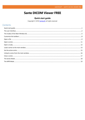
ThyristorsSurface Mount – 100V -600V MCR70xA SeriesDynamic ritical Rate of Rise of Off State Voltage(VD Rated VDRM, RGK 1 k Ω, Exponential Waveform, Gate Open, Tc 110ºC)dv/dt 10 V/µsRepetitive Critical Rate of Rise of On State Current(Cf 60 Hz, IPK 30 A, PW 100 µs, diG/dt 1 A/µs)di/dt 100A/µs3. RGK current not included in measurement.Voltage Current Characteristic of SCR CurrentSymbolParameterVDRMPeak Repetitive Forward Off State VoltageIDRMPeak Forward Blocking CurrentVRRMPeak Repetitive Reverse Off State VoltageIRRMPeak Reverse Blocking CurrentVTMMaximum On State VoltageIHHolding CurrentFigure 1. RMS Current DeratingIHIRRM at VRRMQuadrant 3Main Terminal 2- VoltageOff StateIHIDRM at VDRMVTMFigure 2. On State Power DissipationConduction AngleConduction AngleFigure 4. Transient Thermal Responser(t), TRANSIEN T RESIST ANCE (NORMALIZED)Figure 3. On State CharacteristicsQuadrant 1Main Terminal 2 VTMOn State1.0Z JC(t) R JC(t) r(t)0.10.010.11.010100100010,000t, TIME (ms) 2020 Littelfuse, Inc.Specifications are subject to change without notice.Revised: BO.11/17/20
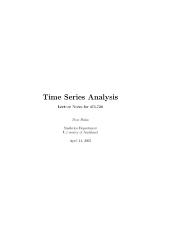
ThyristorsSurface Mount – 100V -600V MCR70xA SeriesFigure 5. Typical Gate Trigger Current vs Junction TemperatureFigure 6. Typical Gate Trigger Voltage vs Junction Temperature1.0VGT, GATE TRIGGER VOLTAGE (VOLTS)IGT, GATE TRIGGER CURRENT ( A)3530252015-40-200204060800.50100 110-40-20TJ , JUNCTION TEMPERA TURE ( C)Figure 7. Typical Holding Current vs Junction Temperature406080100 1102.0IL , LATCHING CURRENT (mA)IH, HOLDING CURRENT (mA)200Figure 8. Typical Latching Current vs Junction Temperature2.01.51.00.50-40002TJ , JUNCTION TEMPERA TURE ( C)-200-200204060TJ , JUNCTION TEMPERA TURE ( C)80100 1101.51.00.50-40-20020406080100 110TJ , JUNCTION TEMPERA TURE ( C) 2020 Littelfuse, Inc.Specifications are subject to change without notice.Revised: BO.11/17/20
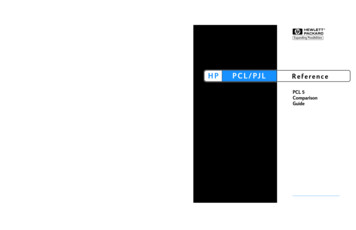
ThyristorsSurface Mount – 100V -600V MCR70xA SeriesDimensionsSoldering FootprintAEb3B6.200.244c24L3D12L4CAb2ZDetail AH35.800.228NOTE 7ecBottom ViewSide ViewbTop ViewZ0.005 (0).13M2.580.1023.000.118CBottom LANEL2C SeatingPlaneLSCALE3: 1mminchesA1L1Detail ARotated 90 C 0.591.65L40.0280.0390.701.00Z0.154-3.90-1. Dimensioning and Tolerancing per ANSI Y14.5M, 1982.2. Controlling Dimension: Inch.STYLE 6:PIN 1. GATE2. ANODE3. CATHODE4. ANODE 2020 Littelfuse, Inc.Specifications are subject to change without notice.Revised: BO.11/17/20
ThyristorsSurface Mount – 100V -600V MCR70xA SeriesDimensionsPart Marking System4DPAK-3Case 369D-01Issue BER44S123ZA1TSEATINSEATINGGPLANEKJFDG0.13 (0.005)M2CR4DLMGYMAXX3xYMAXXG D, M, or N Year Month Assembly Site Lot Serial Code Pb-Free PackageTInchesDimDPAK-3Case 369DStyle 6H3 PLCR70xAGYMAXX3CBV1 2DPAK-3Case 369CStyle 6Pin 8Ordering 600.1501. Dimensioning and Tolerancing per ANSI Y14.5M, 1982.2. Controlling Dimension: Inch.STYLE 6:PIN 1. GATE2. ANODE3. CATHODE4. AT4MCR708AT4G2500Tape & Reel369C4000Units/ Box2500Tape & ReelDisclaimer Notice - Information furnished is believed to be accurate and reliable. However, users should independently evaluate the suitability of and test each product selected for their ownapplications. Littelfuse products are not designed for, and may not be used in, all applications. Read complete Disclaimer Notice at: www.littelfuse.com/disclaimer-electronics 2020 Littelfuse, Inc.Specifications are subject to change without notice.Revised: BO.11/17/20
Dimensioning and Tolerancing per ANSI Y14.5M, 1982. 2. Controlling Dimension: Inch. STYLE 6: PIN 1. GATE 2. ANODE 3. CATHODE 4. ANODE Dimensions Soldering Footprint Dim Inches Millimeters Min Max Min Max A 0.087 0.094 2.20 2.40 A1 0.000 0.005 0