Transcription
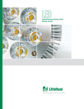
Light-Emitting Diode (LED)Design Guide
LEDLight-EmittingDiode (LED)Design GuideTable of ContentsPageIntroduction3-4Safety and Reliability of LED Bulbs5-7Surge Immunity Requirements for Consumer LED Lighting/Retrofit Lamps8-10Part Selection Matrix for LED Lamp Protection11LED Lighting Compliance with Global Standards12-15Part Selection Guide16-17Design Considerations in MOV Selection18-19Surge Protection Modules and MOV Coordination20-21Protecting Against Temporary Overvoltage22Design Considerations in Fuse Selection to Withstand Surges23Design Considerations for TVS Diodes24-25Design Considerations for PLED Protectors26-28Potential Problems with Alternative LED Lamp OvercurrentProtection Technologies29-33Conclusions34References34Legal Disclaimers35 2016 Littelfuse, Inc.Specifications descriptions and illustrative material in this literature are as accurate as known at the time of publication,but are subject to changes without notice. Visit littelfuse.com for more information.
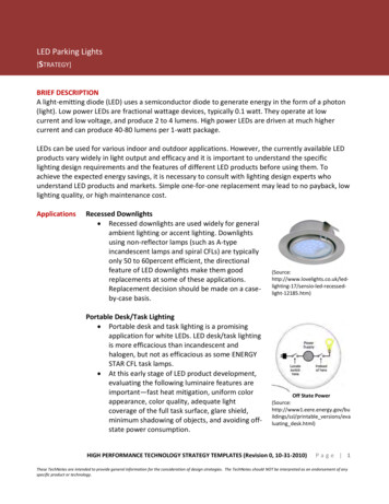
LED Lighting Design GuideIntroductionIntroductionThe first LED lamps were introduced in the late 1990s. Since then, the unit costs havebeen steadily declining by double-digit percentages, making LED lighting technology viablefor commercial, industrial and outdoor lighting applications. In addition, large strides havebeen made in improving the efficiency, lumen output and performance of LED lights. Theglobal LED lighting market is estimated to be 16B in 2012 and expected to reach nearly 40B by 2014 (Figure 1). The US market CAGR for commercial and outdoor LED lightingalone is expected to grow 26-30% through 2016.Market Share by Region, 2010ROW13%N. AmericaEast AsiaLED Lighting Market Value, 2009–2014 (US B)20%5% S. America40%LED share of lighting market to exceed 25% by 201422%EU Global LED Lighting market toreach 16.5B in 2012, 11.3% share oftotal lighting 60% Comml, 25% Resdl, 15%Indl/Instl Key luminaire drivers: traffic lights,roadways, parking lots, and otheroutdoors5030%LED LightingShare of overall lighting market4025%20%3015%2010%1005%20092010Source: Green Market Research20112012201320140%Figure 1. Global market for LED lightingSource: DigitimesIn the commercial sectors, the business case is not only justified from double digitenergy savings but also large maintenance and labor cost reductions. Utility rebates andgovernment financial incentives for energy efficiency further help reduce the initial costof LED lamp and luminaire installations. As most LED lamps are specified to last around50,000 hours versus 1000 hours for incandescent and 8,000 hours for CFLs, fewermaintenance staff hours are required to replace lamps in large facilities. Further, reductionin CO2 emissions by going to LED alternatives is also a key driving factor near and dear togovernment environmental agencies. A single 100W incandescent bulb for example, thatis on four hours a day produces 139 pounds of carbon per year. Switching to a 12 watt LEDlamp which has the equivalent light output of a 75W incandescent will emit only 7.33 lbs.of carbon per year. 2016 Littelfuse LED Lighting Design Guide3www.littelfuse.com
LED Lighting Design GuideIntroduction (continued)Over the next couple of years, LED lighting adoption will be highest in retail accent lightingand cold storage followed by street, highway, parking lot and public structure illumination,and niche applications in commercial building lighting. Street lighting energy efficiencymeasures have been initiated by many local cities and municipalities around the worldseeking to replace high pressure sodium (HPS) lamps with LED lights. For parking lots andparking garages, HPS, metal halides and fluorescents are the main targets for replacement.The United States is leading the way for establishing uniform performance and safetystandards for certain indoor commercial lighting as well as roadway, parking lot and garageillumination. The EPA’s Energy Star specifications apply to LED replacement bulbs forresidential and certain commercial applications. The US Dept of Energy’s Municipal SolidState Street Lighting Consortium’s LED Roadway model spec, and the CommercialBuilding Energy Alliance Parking Lot and Structure Outdoor LED lighting performance specare examples of important documents released in late 2011 and early 2012 respectively.A Littelfuse video, Circuit Protection and Reliability Solutions for the LED LightingMarket, provides an overview of global standards for circuit protection of LED lighting.Littelfuse describesthe market andcircuit protectionneeded for LEDlighting.To view the video,visit: https://vimeo.com/50692101 2016 Littelfuse LED Lighting Design Guide4www.littelfuse.com
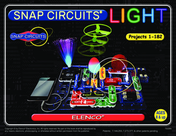
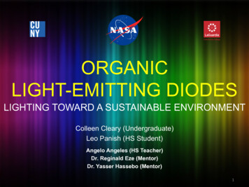
LED Lighting Design GuideSafety and Reliability of LED BulbsSafety and Reliability of LED BulbsAn LED lamp contains power conversion electronics (AC/DC), driver IC for the LEDs, aheat sink for thermal management and optics to optimize light quality. Since LED bulbsare intended to be form factor-compatible with current incandescent and CFL bulbs, theywill have an AC/DC power supply circuit so they can operate from standard bulb “sockets.”(See Figure 2.)LED DriverHeat SinkParabolic ReflectorPackaged LEDLensFigure 2. Typical residential LED lamp construction.Equipment that is directly connected to AC mains (e.g. 120/220VAC) can be damaged byshort circuit and overload conditions caused by component and/or circuit failures inside thebulb. In addition, lightning surges or load switching transients (originating outside the bulb)can create voltage spikes or ring waves that can stress and ultimately damage components,and render the bulb dead. Given that the value proposition for LED bulbs is not only lowerenergy usage, but longer lifetimes, it will be crucial that transient voltage protection istaken into account to eliminate field failures driven by the electrical environment.To view the video, visit:https://vimeo.com/39714285Usha Patel, who leads Littelfuse’sLED initiatives, describes how to usecircuit protection devices to increaseLED lighting reliability and safety. 2016 Littelfuse LED Lighting Design Guide5www.littelfuse.com
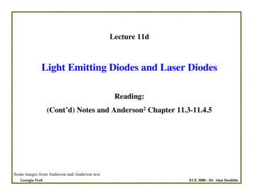
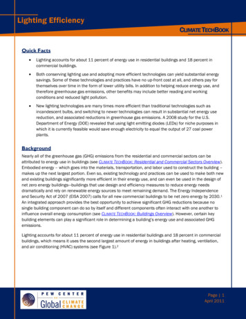
LED Lighting Design GuideSafety and Reliability of LED Bulbs (continued)Click/toggle thegreen boxes belowto view ourproduct lines.Equipment that is directly connected to AC mains (100 to 240VAC)can be damaged by short circuit overload conditions, lightning surgesor load switching transients that create voltage spikes or ring wavesAC Line FuseMOVA fuse with adequate I2T ratingis necessary to pass Energy Starring-wave tests according toIEEE C.62.41A metal oxide varistor (MOV)can help protect the LED bulbfrom overvoltage surges andring-wave effectes by clampingshort-duration voltage impulses.SPDAC InputEMI FilterHigh VoltageDC FuseLine RectifierTVS DiodePTCPLEDA TVS Diode on the dc sidecan be used to protect againsttransients before entry intoconverter circuit.A positive temperaturecoefficient resistor can helpprotect LEDs from over-currentand over-temperature.Open circuitLED protectiondeviceLEDsDC-DC ConverterLOsc.NGIso /StepDownConstantCurrent LEDString DriverTVS DiodeTransient protectionfor energy let throughto the LED circuitMOVSurge protection device withhigh surge withstand MOVs(e.g., 25 - 34mm dia. Sizes)Controller /Opto CouplersFigure 3. Typical LED luminaire driver circuit withtransient and surge energy protection devicesLittelfuse offers complete AC line interface protection as well as transient protection onthe DC side. Its LED Lighting Design video discusses reliability and safety issues that needto be addressed in selecting protective devices for LED retrofit bulbs and luminaires tomeet industry standards. Refer to Figure 3 for an overview of the various components andsystems within the power and control circuits inside an LED lighting assembly.As shown in Figure 3, a Littelfuse AC fuse in series with the line will provide safetyprotection against short circuit and overload conditions. They are available in a wide rangeof form factors, amperage ratings, voltage ratings, breaking capacity and mounting optionsto provide design flexibility to the design engineer.The AC/DC power conversion circuit can use either isolated or non-isolated topologies.Transient protection is not only critical for the DC side electronics but more importantlythe LED load. The ICs can be protected by nature of isolated bias windings and filteringelements. However, insufficient spacing on the PCB, flashover of physically smallcomponents, or unintentional coupling through transformers and opto couplers can fail dueto inadequate transient protection. A well designed surge protection scheme will limit thepeak voltage and current envelopes to avoid coupling through unintentional paths. 2016 Littelfuse LED Lighting Design Guide6www.littelfuse.com
LED Lighting Design GuideSafety and Reliability of LED Bulbs (continued)In the case of non-isolated LED drivers which are prominent in many retrofit lamps andlower power applications, the LEDs themselves can be damaged by the surge energyas there is no transformer isolation between the AC input and the LEDs on the DC side.Isolated circuits, such as flyback converters, are more robust since their transformersprovide some degree of isolation and surge protection. Nevertheless, protection isstill required to limit higher surge events, especially in outdoor lamp and luminaireenvironments. High energy surge events, such as those caused by nearby lightning strikescan flash over from the primary to the secondary side.The MOV across the AC power input in Figure 3 is the key to providing surge clampingprotection against lightning related transients. An MOV in this location is a cost-effectiveway to minimize transient energy that could make its way into downstream electronics.MOV selection is based on a number of parameters, including voltage rating, peak pulsecurrent, energy rating, disk size and lead configuration. Littelfuse provides varistors withdisk diameter down to 5mm (ZA series), which allows them to be used in the spaceconstrained power supply section of an LED lamp. Littelfuse Application Note 9767provides a detailed explanation of MOV technology.The MOV and the fuse must be a coordinated solution so that energy needed to melt thefuse element (also referred to as “i2t” value) is high enough to allow the MOV to operateunder surge conditions without causing the fuse to open (also known as nuisance opening).In other words, during clamping and dissipation of surge energy, the fuse should not open.It should only open when an overload or short circuit condition occurs.There will be instances when the circuit is not able to survive surge events, even witha varistor on the AC input. In these cases, a TVS diode can be added at the input of thepower converter stage. Referring again to Figure 3, the TVS diode provides secondaryprotection against transients. The “let through” energy from the varistor will be furtherclamped by the TVS diode to a level that the circuit can survive.Littelfuse has many options for fuses, MOVs and TVS diodes, based on form factor, spaceconstraints, electrical parameters and cost. (See embedded links in the green boxes ofFigure 3.) 2016 Littelfuse LED Lighting Design Guide7www.littelfuse.com
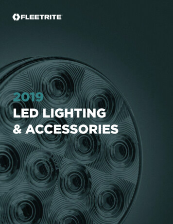
LED Lighting Design GuideSurge Immunity Requirements for Consumer LED Lighting/Retrofit LampsSurge Immunity Requirements for Consumer LED Lighting/Retrofit LampsFuses, MOVs and TVS diodes from Littelfuse are critical in helping the lamp manufacturerpass important regulatory and safety standards. The United States is leading the wayfor establishing uniform performance and safety standards for certain indoor commerciallighting as well as roadway, parking lot and garage illumination. EPA’s Energy Star surgespecifications apply to the PAR30, PAR38, A-19, MR16, Candelabra, G-globe, and R-reflectortypes of LED retrofit lamps.Some IEC Requirements. With the exception of the US, which uses other standards,overvoltage transient surge testing per IEC 61000-4-5 is a global requirement for LEDlighting assemblies. In addition, part of IEC61547, “Equipment for General Lighting Purposes”requires EMC immunity testing. Figure 4 shows two waveforms that define rise time andduration of the test voltage and current.1.0 1.01.0 1.0FrontFrontTimeTime 8 μs 8 μs0.6 0.60.6 0.60.4 0.4DurationDuration 50 μs50 μs0.2 0.2000I(t)/Ip0.8 0.8I(t)/Ip0.8 0.8V(t)/VpV(t)/VpFrontFrontTimeTime 1.2 μs1.2 μsDuration 20μsDuration 20μs0.4 0.40.2 0.20202040406060TimeTime(μs) (μs)80800100 circuitvoltagevoltage000101020203030TimeTime(μs) cuitshort-circuitcurrentcurrentFigure 4. IEC 61000-4-5 surge immunity test waveforms:1.2 50µs open circuit voltage and 8 20µs short circuit current. 2016 Littelfuse LED Lighting Design Guide8www.littelfuse.com50
LED Lighting Design GuideSurge Immunity Requirements for Consumer LED Lighting/Retrofit Lamps (continued)Additional test requirements include: For self-ballasted lamps and luminaires 25W, 500V/250A: Apply 500V L-L with 2 ohmsource impedance and 1kV L-G with 12 ohms impedance. For luminaire 25W, 1000V/500A: Apply 1kV L-L with 2 ohm source impedance and2kV L-G with 12 ohms impedance. Number of surges: 10 strikes, 5 and 5- at phase angles 90/270, 1 minute betweeneach strike.In the US, manufacturers generally must meet Energy Star transient voltage surgespecifications for LED replacement bulb assemblies used in residential and certaincommercial applications. For example, Version 1.4 of the Energy Star program requirementsdefine a ring wave transient test for integral LED lamps (Figure 5).Other test requirements include: Test Level: 2.5kV/83A, line-to-line (ANSI/IEEE C.62.41-1991, Class A operation). Number of surges: 7 strikes in common mode and 7 in differential mode, 1 minutebetween each strike.1.0Rise Time 0.5 μs0.810 μs0.6Figure 5. Energy Star transient voltageimmunity test waveform: 0.5µs rise time 10µs duration (100kHz) ring wave.V(t)/Vp0.40.20-0.2-0.4-0.6-0.8-1.00102030Time (μs)The 100 kHz Ring Wave (voltage and current) 2016 Littelfuse LED Lighting Design Guide9www.littelfuse.com
LED Lighting Design GuideSurge Immunity Requirements for Consumer LED Lighting/Retrofit Lamps (continued)It is often the case that engineers will want to test the robustness of their application andtheir protection scheme during the qualification process. For those that lack in-housesurge test equipment, Littelfuse offers the use of lab facilities to verify the design of theirapplication. This testing can identify problems at a stage early enough that they can becorrected before field issues occur. Figure 6 illustrates the voltage and current waveforms foran Energy Star surge test conducted by Littelfuse on an LED bulb assembly. The circuitry forthis A19 lamp assembly included the Littelfuse 0451/0453 series fuse installed on the lampdriver board. The LED was lit and was fully operational before and after application of thesurge, thus passing Energy Star requirements.Figure 6. Typical waveform of 2.5kV, 100kHz ring wave surge test. 2016 Littelfuse LED Lighting Design Guide10www.littelfuse.com
LED Lighting Design GuidePart Selection Matrix for LED Lamp ProtectionPart Selection Matrix for LED Lamp ProtectionIt’s important for engineers to avoid the trap of trying to use the same protection devicesfor every LED lamp assembly they design. Each application should be evaluated based onthe operating environment, circuit operating parameters, and the pertinent surge protectionspecifications. Table 1 lists several Littelfuse part numbers for fuses, MOVs, and TVS diodesthat could fit many of these applications and their associated surge test requirements.Transient Surge SpecFuse OptionsMOV OptionsTVS Diode047001.5 (1.5A SMT 1206 125V)0453001 (1A SMT 2410 125V)0454001 (1A SMT 2410 125V)0473001 (1A Pico 125V)39211000000 (TE5 250V 1A)38211000000 (TR5 250V Y STAR Program Requirements for Integral LED Lamps (for USA) 1. ANSI/IEEE C.62.41-1991, Class A operation. 0.5µs 100kHz Ring Wave,2.5kV, 7 strikes common and differential modesIEC 61547 Equipment for general lighting purposes - EMC immunity requirements (for Europe/ Asia / Australia)1. IEC 61000-4-5 Surge Immunity Test. For lamps 25W:1.2 50µs/8 20µs combination wave 500V/250A line-to-line test (10strikes, 5 at phase angles 90, 5– at phase angle 270)087601.6 (3.6x10 250V 1.6A)39211000000 (TE5 250V 1A)38211000000 (TR5 250V 1A)0476003 (SMT 2410 250V 3A)0465001 (SMT 4818 250V ASMBJ400ASMBJ440A1.5KE400A1.5KE440CA2. IEC 61000-4-5 Surge Immunity Test. For lamps 25W:1.2 50µs/8 20µs combination wave 1000V/500A line-to-line test (10strikes, 5 at phase angles 90, 5– at phase angle 270)0877002 (2A 250V 3.6x10)39211600000 (TE5 250V 1.6A)38211600000 (TR5 250V 1.6A)046501.6 (250V SMT 4818 E: MOVs were tested with 1.2 50µs open circuit voltage waveform and 8 20µs short circuit current waveform forming a combo waveform with 2 ohmsource impedance. Standard method was used for testing the MOVs per datasheet specifications which consisted of driving relevant surge current through thepart with the generated combination wave. In real world events, actual peak current through the lamp with typical circuit impedance path will likely be lower.Littelfuse has tested the above part selections to a more stringent level as it complies with our internal testing standards.Table 1. A sampling of Littelfuse devices designed for LED lamp surge protection. 2016 Littelfuse LED Lighting Design Guide11www.littelfuse.com
LED Lighting Design GuideLED Lighting Compliance with Global StandardsLED Lighting Compliance with Global StandardsMany countries are in the midst of developing protection standards for LED lighting. As thislighting technology matures, these requirements in are in a state of flux and may becomemore stringent. Table 2 is a matrix of current safety and surge standards prevalent in keygeographic areas of the world.United StatesEuropeS. AmericaJapanSurge Immunity (Combo wave) Energy Star (Based IEC/EN 61547 IEC/1.2 50µs Voc/ 8 20µs Iscon IEEE C62.41.2)EN 61000-4-5Ring wave 2.5kV500V/250AIntegrated LED light bulbs1kV/500A(E27 Base Europe / E26 Base USA) 100kHz Class A(LED retrofit lamps and indoorcommercial)TaiwanChinaKoreaJIS C 61000-4-5(Based on IEC/EN61000-4-5)500V/250A1kV/500ACNS 14676-5GB/T 18595 (Based K61547 (Based on(Based on IEC/EN on IEC/EN 61547)IEC/EN A1kV/500A1kV/500AJIS C 61000-4-5(Based on IEC/EN61000-4-5)4kV/2kACNS 14676-5(Based on IEC/EN61000-4-5)4kV/2kASurge Immunity (Combo wave)1.2 50µs Voc/ 8 20µs IscLED Outdoor Luminaires(Street Lighting, Parking LotLighting)DOE (Based onIEEE C.62.41.2)Category C-Low6kV/3kACategory C-High20kV/10kAANSI/NEMA(spec. no. TBD)IEC/EN 61547 IEC/EN 61000-4-54kV/2kA 6kV/3kA10kV/5kASafetyUL 8750, UL 1310,UL 1993, UL 1598IEC/EN 62560 bulb DENAN standardsIEC/EN 60598JEL 801LuminaireIEC/EN 61347driverIEC/EN 62031 LEDarray/moduleCNS standardsGB/T 17626.5KS C IEC61000-4-5(Based on IEC/EN (Based on 09/IEC62031 LEDModule for generallighting-safetyKS standardsTable 2. Summary matrix of global protection standards for LED lightingSafety refers to overcurrent protection, particularly short circuit and overload protection. InNorth America, UL8750 is the Standard for Safety of LED Equipment, which pertains toresidential LED lamps and outdoor luminaire assemblies. The purpose of this requirement isto minimize the risk of shock and fire. It calls out the use of an overcurrent protection deviceto interrupt or limit the current during a short circuit or overload condition. Fuses are the mostwidely used and reliable protection technology to protect against such conditions. Outsidethe US, the IEC/EN 61347 LED driver (power supply) specification and IEC/EN 62031 for LEDarrays/modules contain safety requirements for these power supplies.In Europe and other countries outside the United States, the surge immunity requirementsare referenced in documents such as IEC/EN 61547 that references IEC/EN 61000-4-5,which delineates different surge testing levels based on 8x20µs short circuit currentcombination waveform. For outdoor lighting applications, these levels can range from4kV/2kA in many Asian countries up to 10kV/5kA in Europe. 2016 Littelfuse LED Lighting Design Guide12www.littelfuse.com
LED Lighting Design GuideLED Lighting Compliance with Global Standards (continued)In the US, ANSI/IEEE C.62.41-2002 is a very important specification to consider, because it iseither the primary or secondary reference for surge immunity testing. This standard definesfour lighting location categories and associated transient surge testing requirements. Thecategories correspond to the physical location of the LED luminaire whether located indoorsor outdoors. For instance, the outdoors luminaires that fall into Category C (high or low testrequirements) are far more susceptible to lightning strikes and hence will be subject to themost stringent surge immunity testing. Figure 7 illustrates these locations. Table 3 is asummary of the IEEE C.62.41-2002 surge levels and where they apply.Figure 7. Lighting locations defined by ANSI/IEEE C.62.41-2002, which determine the type ofprotective devices needed in an LED luminaire.Location CategoryWaveformPk Voltage (kV)Pk Current (kA)SourceApplication1.2/50µs8/20µsImpedance (Ohms)A (Indoors)60.512Indoor Commercial Bldg/ Offices/ RetailB632Lighting near Service EntranceC Low632Commercial/ Industrial/ Parking GarageC High (Outdoors)*20102Street/ Hwy/ Parking Lot/ Area Flood/ OutdoorLocation CategoryPk Voltage (kV)Pk Current (kA)Waveform0.5µs 100kHz Ring WaveSourceImpedance (Ohms)A (Indoors)60.230B60.512C Low or High60.512*A combination waveform where specified peak current is calibrated on the tester by shorting the output together prior toconnection to the luminaire. Single phase modes: L-N L-G N-G. Polyphase Modes: L-L L-N L’s-GTable 3. IEEE C.62.41-2002 test requirements for LED luminaires. 2016 Littelfuse LED Lighting Design Guide13www.littelfuse.com
LED Lighting Design GuideLED Lighting Compliance with Global Standards (continued)LED luminaires today are over two times the cost of the incumbent HPS lighting assemblies.However, LEDs are expected to last nearly 100,000 hours – about three to four times thatof HPS luminaires, while consuming 80% less energy. The US has established uniformperformance and safety standards for Outdoor lighting including roadway, parking lot andgarage illumination.UL 1598 is the Standard for Safety of Luminaires which garners compliance from a majorityof outdoor lighting manufacturers in N. America. This specification covers requirementsfor overcurrent protective devices such as fuses that are used for overload and short circuitprotection in luminaires. These requirements are similar to those in UL 60950. In addition, UL8750 - the Standard for LED Equipment for use in Lighting Products also calls out the use ofovercurrent protective devices such as fuses.The US Department of Energy’s (DOE) Municipal Solid-State Street Lighting Consortium(MSSSLC) has released a model specification for LED roadway luminaries for use by citiesand municipalities when specifying LED lighting requirements. This DOE specification isprojected to become an ANSI/NEMA C136.x requirement in the near future. The DOE’s goalis to protect LED luminaire investments by establishing strong safety and surge standards, solight fixtures will require minimal maintenance and are able to last a minimum of five yearswithout service disruption. These will be important characteristics as cities and municipalitiesbegin lighting replacement and retrofit programs, which will involve large capital investments.To support this initiative, funding and subsidy programs such as the American Recoveryand Reinvestment Act (ARRA) are helping many cities reduce the initial cost of these LEDlighting projectsThe DOE specification details performance, safety and surge immunity requirements.Excerpts from this specification are listed in Table 4 and Table 5.ParameterTest Level/ Configuration1.2/50µs Open Circuit Voltage PeakLow: 6 kV. High: 10kV*8/20µs Short Circuit Current PeakLow: 3 kA. High: 10kACoupling ModesL1 toPE, L2 to PE, L1 to 72Polarity and Phase AnglePositive at 90 and Negative at 270 Test Strikes5 for each Coupling Mode and Polarity/Phase AnglecombinationTime Between Strikes1 minuteTotal Number of Strikes 5 strikes 3 coupling modes 2 polarity/phase angles 30 totaI strikes*This is a MINIMUM requirement. Note that for most combination wave generators, which have asource impedance of 2W, the generator charging voltage will need to be raised above the specifiedlevel (to somewhere in the vicinity of 20kV) to obtain the specified current peak.Table 4. DOE MSSSLC 1.2/50µs Combination Wave Test Specification 2016 Littelfuse LED Lighting Design Guide14www.littelfuse.com
LED Lighting Design GuideLED Lighting Compliance with Global Standards (continued)ParameterTest Level/ ConfigurationShort Circuit Current Peak0.5kAOpen Circuit Voltage Peak6kVCoupling ModesL1 to PE, L2 to PE, L1 to L2Polarity and Phase AnglePositive at 90 and Negative at 270 Test Strikes5 for each Coupling Mode and Polarity/Phase AnglecombinationTime between Strikes1 minuteTotal Number of Strikes 5 strikes 3 coupling modes 2 polarity/phase angles 30 total strikesTable 5. DOE MSSSLC 0.5µs Rise Time – 100kHz Ring Wave Test SpecificationThe DOE requirements are similar to those in IEEE C.62.41-2002, IEEE’s RecommendedPractice on Characterization of Surge in Low Voltage (1000V or less) in AC Power Circuits,with a couple of small differences. DOE’s MSSSLC calls out a combination wave andnot separate and successive application of the 10kV/10kA surge levels as stated inIEEE C.62.41-2002.The DOE MSSSLC waveform is a combination 1.2/50μs open circuit voltage and 8/20μsshort circuit current waveform (Table 4). To perform this test the specified peak current iscalibrated on the tester by shorting the output to ground prior to connection to the luminaire.The actual current that gets driven through the luminaire is a result of the combination waveand will likely be lower based on the effective impedance of the luminaire. In turn, the actualcurrent that would run through the MOVs (at the AC input of Figure 3, or elsewhere) willprobably be less than the total current that enters the luminaire, based on available currentpaths and their effective impedances. This test setup is depicted in Figure 8.Test in LFTest on whole luminaireLuminaireA110kAA2A3PoweringCircuitryA1 10kA A2 (slightly less than 10kA) A3Figure 8. Littelfuse MOVs tested with 2-ohm sourceimpedance per MSSSLC combination waveform. 2016 Littelfuse LED Lighting Design Guide15www.littelfuse.com
LED Lighting Design GuidePart Selection GuideThe peak voltage in this test was adjusted to a bit higher than the specified 20kV in order to drive exactly 10kA of peakcurrent. In real world events, actual peak current through an MOV at the AC input will likely be lower than the total currentthat enters the luminaire, depending on available current paths. Littelfuse has tested the parts listed in Table 1 partselections to a more stringent level as it complies with our internal testing standards.To summarize, the DOE 10kA combination wave is a less stringent test than the Category “C-High” portion of the C62.412002 requirement. However, it still requires a 30-strike total with strikes spaced a minute apart (i.e., each MOV willexperience 10 hits). Also, the IEEE C.62.41-2002 spec for the C-high portion specifies that the 6kV/0.5kA (12-ohm sourceimpedance) ring wave (0.5μs/100kHz) test is optional. However in the DOE model specification, this is mandatory. This levelis low energy and easier to pass but nonetheless requires testing.Part Selection GuideLittelfuse is committed to helping LED lighting manufacturers meet or exceed these specifications by providing robustcoordinated overcurrent and overvoltage protection solutions for all surge levels. Littelfuse has performed extensive testingon the suggested components and in most cases at more stringent levels than what the above specifications outline. Forcompanies not equipped to do their own testing, Littelfuse can assist with the testing. 2016 Littelfuse LED Lighting Design Guide16www.littelfuse.com
LED Lighting Design GuidePart Selection Guide (continued)Table 6 is a comprehensive part selection guide for commercial and outdoor lighting systemsorganized by surge level that needs to be met. It provides both overcurrent and overvoltagecomponent recommendations that will pass both safety and surge starndards respectively.Indoor - IEC / IEEEFuse OptionsMOV Options443002 (2A 250V)20901.5 (1.5A 350V)219001 (1A 250V)3831250 (2.5A 300V)3921160 (1.6A, 250V)3961250 (2.5A 125V)8041100 (1A 250V)V14E300P (14mm 300V)V14E320P (14mm 320V)TVS Diode(DC)PLED (Bypass for OpenLED String Protection)IEC 61000-4-5 Installation Class 31.2 50µs Voltage 8 20µs Current Combination Wave2kV 1kA (2ohm), 40 strikes, 5 and 5- at phase angles0/90/180/270ANSI/IEEE C62.41.2-2002 Location Category A0.5µs 100kHz Ring Wave6kV 0.2kA (30ohm)1.2 50µs Voltage 8 20µs Current Combination Wave6kV 0.5kA (12ohm)45402.5 (2.5A 125V)443002 (2A 250V)473003 (3A 125V)20901.5 (1.5A 350V)219001 (1A 250V)3831250 (2.5A 300V)3921160 (1.6A, 250V)V300LA10P (10mm 300V)V320LA10P (10mm 320V)PLED6S(ILED 1A 400A1.5KE440CAANSI/IEEE C62.41.2-2002 Location Category B0.5µs
Specifications descriptions and illustrative material in this literature are as accurate as known at the time of publication, but are subject to changes without notice.