Transcription
Air Brake Handbook Compressors Valves Wheel End Solutions Air Treatment Integrated Modules Electronics
2009 Bendix Commercial Vehicle Systems LLC All Rights Reserved
The Air Brake Handbook 2009 Bendix Commercial Vehicle Systems LLC All Rights ReservedMore info: visit www.bendix.com1-800-AIR-BRAKE (1-800-247-2725)1
Device IndexAlphabetic Device IndexA-18 Controller Assy. . . . . . . 42Actuators . . . . . . . . . . . . . 17AD-2 Air Dryer. . . . . . . . . . 12AD-4 Air Dryer. . . . . . . . . . 12AD-9 Air Dryer. . . . . . . . . . 12AD-IP Air Dryer . . . . . . . . . 12AD-IS Air Dryer Module . . . . . 12AD-SP Air Dryer . . . . . . . . . 13AF-3 In-line Air Filter . . . . . . 13Air Disc Brakes . . . . . . . . . . 20ASA-5 Automatic Slack Adjuster 18BA-921 Air Compressor . . . . 8, 9BA-922 Air Compressor . . . . . 8-9BASIC Test Kit . . . . . . . . . . . 9Bendix Modules . . . . . . . . . 45BP-R1 Bobtail ProportioningRelay Valve . . . . . . . . . . . 22BVA-85 Brake Valve Actuator . . 46BX-2150 Air Compressor . . . . . 8Converter Dolly Brakes. . . . . . 33Cyclone DuraDrain TrailerWater Separator . . . . . . . . 13D-2 Governor . . . . . . . . . . 10DC-4 Double Check Valve . . . 14DD3 Safety Actuator . . . . . . 17Dryer Reservoir Module . . . . . 12DS-2 Double Check and StopLight Switch . . . . . . . . . . . 14DuraFlo 596 Air Compressor . 8, 9E-10 Brake Valve . . . . . . . . 15E-10P Brake Valve . . . . . . . 15E-10PR Retarder ControlBrake Valve . . . . . . . . . 15, 16E-12 , E-15 Brake Valves . . . 15E-14 Brake Valve . . . . . . . . 15E-6 Brake Valve . . . . . . . . . 15E-7 Brake Valve. . . . . . . . . 15E-8P Brake Valve . . . . . . . . 15EC-30 ABS/ATC Controller . . . 36EC-60 ABS/ATC Controller . . . 36ESP Functionality . . . . . . . . 39EverFlow Module . . . . . . . . 132FD-3 Fan Clutch . . . . . . . . 46FD-l Fan Clutch . . . . . . . . . 46Inlet Check Valve. . . . . . . . . 10Inlet Regulating Valve . . . . . . 10LP-2 and LP-3 Low PressureIndicators . . . . . . . . . . . . 11LQ-5 Bobtail Ratio Valve . . . . 22M-32 and M-32QR Modulators 35MC-30 Controller Assy. . . . . . 42MV-3 Dash Control Module . . . 29PE-4 Control Valve . . . . . . . 32PP-1 and PP-2 Valves . . . . . 24PP-1 Control Valve . . . . . . . 34PP-3 Control Valve . . . . . . . 24PP-5 Push-Pull Control Valve. . 27PP-7 Control Valve . . . . . . . 24PP-8 Control Valve . . . . . . . 24PP-DC Park Control Valve . . . 28PR-3 Reservoir Control Valve. . 34PR-4 Pressure Protection Valve 14PuraGuard QC OilCoalescing Filter . . . . . . . . 13QR-1 Quick Release Valve . . . 21QR-1C Quick Release Valve . . 26QR-L Quick Release Valve . . . 21QRN-2 Quick Release Valve . . 21QRV Quick Release Valve . . . 21R-12DC Relay Valve . . . . . . 23R-12P Relay Valve . . . . . 23, 34R-12 Relay Valve . . . . . . . . 23R-14 Relay Valve . . . . . . . . 23R-6 Relay Valve. . . . . . . . . 23R-7 Modulating Valve . . . . . . 23R-8P Relay Valve . . . . . . . . 23R-8 Relay Valve. . . . . . . . . 23RD-3 Control Valve . . . . . . . 27RDU (Remote Diagnostic Unit) . 44RE-6NC Relay Emergency Valve 34Reservoirs . . . . . . . . . . . . 11RV-1 Pressure Reducing Valve . 14S-Cam Brakes . . . . . . . . . . 19SB-1 Spring Brake Actuator . . 17SC-3 Single Check Valve . . . . 11SC-PR Valve . . . . . . . . . . 13SD3 Roto Safety Actuator . . . 17SDS-9600 Trailer SuspensionDump Valve . . . . . . . . . . . 27SL-4 and SL-5 Stop LampSwitches . . . . . . . . . . . . 26Spring Brake Actuators. . . . . . 17SR-2 Spring Brake Valve . . . . 31SR-4 Spring Brake Valve . . . . 31SR-5 Spring Brake Valve . . . . 31SRC-7000 TrailerSpring Brake Valve . . . . . . . 31ST-1 , ST- 3 and ST-4 Safety Valves. . . . . . . . . . . 10SureStroke Indicator . . . . . . 18SV-1 Synchro Valve. . . . . 27, 34SV-4 Trailer Release Valve . . . 34System-Guard Trailer Air Dryer . 13TABS-6 Trailer ABS . . . . . . . 41TABS-6 Advanced Trailer ABS . . 41TABS-6 Advanced MC Trailer ABS 41TC-2 Trailer Control Valve . . . 29TC-6 Trailer Control Valve . . . 29TE-1 Trailer EmergencyStop Light . . . . . . . . . . . 32TP-3 Tractor Protection Valve . . 30TP-3DC Tractor Protection Valve 30TP-4 Tractor Protection Valve . 30TP-5 Tractor Protection Valve . 30TR-3 Valve . . . . . . . . . . . 27Trailer Control (TC) Valves . . . . 29Tu-Flo 550 Air Compressor . . . 8, 9Tu-Flo 750 Air Compressor . . . 8, 9TW-1 , TW-3 and TW-6 Control Valves . . . . . . . . . 26TW-11 Valve . . . . . . . . . . 26WS-24 Wheel Speed Sensors . 35Yaw Stability . . . . . . . . . . . 39More info: visit www.bendix.com1-800-AIR-BRAKE (1-800-247-2725)
Handbook Section IndexHow to use the Air Brake HandbookThis nine-section handbook provides an introduction to the use and operation of Bendixair brake systems and devices.Components are introduced and shown with typical system diagrams to show wherethey are used. As new components are introduced and their function explained, theygradually build up to a complete functioning air brake system.Partial system-drawings, throughout the manual, assist in explaining of the use of thecomponents. See the front inside cover and the fold-out back cover for examples ofvehicle system schematics.ContentsSection 6: Antilock Braking SystemsDevice Index. . . . . . . . . . . . . . . . . . . . . . . . . . . . . . . . . . 2Introduction . . . . . . . . . . . . . . . . . . . . . . . . . . . . . . . . . 35General Precautions. . . . . . . . . . . . . . . . . . . . . . . . . . . . 4ABS Components . . . . . . . . . . . . . . . . . . . . . . . . . 35-36Section 1: An Overview5Truck and Tractor ABS Operation. . . . . . . . . . . . . . 36-37Overview. . . . . . . . . . . . . . . . . . . . . . . . . . . . . . . . . . . . . 5ATC Operation . . . . . . . . . . . . . . . . . . . . . . . . . . . . . . . 37Section 2: The Charging System6-14Compressors . . . . . . . . . . . . . . . . . . . . . . . . . . . . . . . 7-9Compressor Maintenance Guidelines . . . . . . . . . . . . . . 9Governors and Components . . . . . . . . . . . . . . . . . . . . 10Reservoirs and Components . . . . . . . . . . . . . . . . . . . . 11Air Dryers . . . . . . . . . . . . . . . . . . . . . . . . . . . . . . . . 12-13Additional Charging System35-Advanced ABS Operation, Features. . . . . . . . . . . 38-40Trailer ABS Components and Operation . . . . . . . . 41-43Troubleshooting Truck, Tractor and Trailer ABS. . . 44-45Section 7:Additional Systems and Components46-47Adaptive Cruise Control . . . . . . . . . . . . . . . . . . . . . . . . 46Tire Pressure Monitoring Systems . . . . . . . . . . . . . . . . 46Related Components . . . . . . . . . . . . . . . . . . . . . . . . . 14Section 3: The Control System15-27Dual Circuit Brake Valves . . . . . . . . . . . . . . . . . . . . 15-16Actuators . . . . . . . . . . . . . . . . . . . . . . . . . . . . . . . . . . . 17Slack Adjusters . . . . . . . . . . . . . . . . . . . . . . . . . . . . . . . 18Foundation Brakes: S-Cam and Air Disc . . . . . . . . 19-20Quick Release, Ratio Valves . . . . . . . . . . . . . . . . . . . . 21Ratio, Proportioning Valves . . . . . . . . . . . . . . . . . . . . . 22Relay Valves. . . . . . . . . . . . . . . . . . . . . . . . . . . . . . . . . 23Push-Pull Valves. . . . . . . . . . . . . . . . . . . . . . . . . . . . . . 24Modules . . . . . . . . . . . . . . . . . . . . . . . . . . . . . . . . . . . . 47Section 8: The Fundamentals of Air Braking48-58Friction, Braking Force . . . . . . . . . . . . . . . . . . . . . . 48-49Leverage. . . . . . . . . . . . . . . . . . . . . . . . . . . . . . . . . 50-51Deceleration . . . . . . . . . . . . . . . . . . . . . . . . . . . . . . 51-52Compressed Air . . . . . . . . . . . . . . . . . . . . . . . . . . . 53-55Compressed Air Brakes . . . . . . . . . . . . . . . . . . . . . 55-56S-Cam and Air Disc Brakes . . . . . . . . . . . . . . . . . . . . . 56Air Brake System Balance: Pneumatic Systems . . . . . 57Air Brake System Balance: Mechanical Systems . . . . 58Spring Brake Valves . . . . . . . . . . . . . . . . . . . . . . . . . . . 25Lever Operated Control Valves . . . . . . . . . . . . . . . . . . 26Section 9:Additional Control Valves . . . . . . . . . . . . . . . . . . . . 26-27Air Brake System Troubleshooting Tests59-62Section 4: Tractor Parking, Trailer Charging/Parkingand Emergency Systems28-32Bendix Literature . . . . . . . . . . . . . . . . . . . . . . . . . . . . . 63Park Control Valves . . . . . . . . . . . . . . . . . . . . . . . . . . . 28About Bendix . . . . . . . . . . . . . . . . . . . . . . . . . . . . . . . 64Dash Control Modules . . . . . . . . . . . . . . . . . . . . . . . . . 29Trailer Control Valves . . . . . . . . . . . . . . . . . . . . . . . . . 29Tractor Protection Valves . . . . . . . . . . . . . . . . . . . . . . . 30Front Inside . . . . . . . . Typical Tractor System SchematicTrailer Spring Brake Valves . . . . . . . . . . . . . . . . . . 31-32Back Inside . . . . . . . . . Typical Truck System SchematicSection 5: Converter Dolly Brakes33-34Trailer/Converter Dolly Brakes . . . . . . . . . . . . . . . . 33-34Fold-in Back . .Typical Tractor System with ESP StabilityFold-out Back . . Typical Truck System with ESP StabilityDIN symbols are used in this handbook.More info: visit www.bendix.com1-800-AIR-BRAKE (1-800-247-2725)3
General PrecautionsIMPORTANTThe systems presented in this manual are intended for illustrative purposesonly and are not intended to be used for actual vehicle piping.Air Brake System General PrecautionsWARNING! PLEASE READ AND FOLLOW THESEINSTRUCTIONS TO AVOID PERSONAL INJURY OR DEATH:When working on or around a vehicle, the following generalprecautions should be observed at all times.1. Park the vehicle on a level surface, apply theparking brakes, and always block the wheels.Always wear safety glasses.2. Stop the engine and remove ignition key whenworking under or around the vehicle. Whenworking in the engine compartment, the engineshould be shut off and the ignition key should beremoved. Where circumstances require that theengine be in operation, EXTREME CAUTIONshould be used to prevent personal injury resultingfrom contact with moving, rotating, leaking, heatedor electrically charged components.7. Never connect or disconnect a hose or linecontaining pressure; it may whip. Never removea component or plug unless you are certain allsystem pressure has been depleted.8. Use only genuine Bendix replacement parts,components and kits. Replacement hardware,tubing, hose, fittings, etc. must be of equivalentsize, type and strength as original equipment andbe designed specifically for such applications andsystems.3. Do not attempt to install, remove, disassembleor assemble a component until you have readand thoroughly understand the recommendedprocedures. Use only the proper tools and observeall precautions pertaining to use of those tools.9. Components with stripped threads or damagedparts should be replaced rather than repaired. Donot attempt repairs requiring machining or weldingunless specifically stated and approved by thevehicle and component manufacturer.4. If the work is being performed on the vehicle’sair brake system, or any auxiliary pressurized airsystems, make certain to drain the air pressurefrom all reservoirs before beginning ANY workon the vehicle. If the vehicle is equipped withan AD-IS air dryer system or a dryer reservoirmodule, be sure to drain the purge reservoir.10. Prior to returning the vehicle to service, makecertain all components and systems are restoredto their proper operating condition.5. Following the vehicle manufacturer’s recommendedprocedures, deactivate the electrical system in amanner that safely removes all electrical powerfrom the vehicle.46. Never exceed manufacturer’s recommendedpressures.11. For vehicles with Antilock Traction Control (ATC),the ATC function must be disabled (ATC indicatorlamp should be ON) prior to performing any vehiclemaintenance where one or more wheels on a driveaxle are lifted off the ground and moving.More info: visit www.bendix.com1-800-AIR-BRAKE (1-800-247-2725)
IntroductionSection 1: An OverviewAir SupplyThe vehicle’s compressor takes in filtered air, eitherat atmospheric pressure from the outside or alreadyat an increased pressure (e.g. from the engineturbocharger), and compresses it. The compressedair is delivered to the air dryer where water and a smallamount of oil is removed. The air then travels intothe air reservoirs (“air tanks”) - typically delivered to arear brake system reservoir and a front brake systemreservoir as well as any attached trailer reservoirs. Foreach system, the air pressurizes the reservoir and theair hoses all the way to the next control valve, wherethe air pressure remains, ready to be used.A vehicle may use compressed air for many tasks.Some examples are: to provide force for braking, todeliver air to a particular component, to off-load bulkgoods, etc.Normal BrakingWhen the driver applies the foot brake, a plunger withinthe foot brake valve moves, opening channels withinthe valve that allow the air pressure waiting there topass through and be delivered to the rear and frontbrake systems. The pressure quickly increases in thebrake chambers and applies force to the push rod,transferring the force to the S-Cam or air disc brake.(See page 19 for more about foundation brakes.)Frictional forces slow the wheels and the vehiclecomes to a stop. When the brakes are released, theair in the brake chambers is able to be quickly releasedand enable the vehicle to drive away.Vehicle ParkingVehicles are parked using powerful springs, whichare part of the spring brake assembly, to engage thebrakes and hold the vehicle in position. When thedriver prepares to move away and releases the parkingbrake, the spring force is countered by the introductionof air pressure. An anti-compounding valve in thesystem design helps prevent the application of boththe spring and service brakes together.Antilock Braking Systems (ABS)Most commercial vehicles use electronic AntilockBraking System (ABS) to help improve braking whenexcessive wheel slip, or wheel lock-up, is detected.Bendix Electronic Control Units (ECUs) use patentedtechnology to monitor wheel speeds (on all wheelsequipped with speed sensors) and use ABS modulatorvalves to adjust or pulse the braking force being*ESP is a registered trademark of Daimler and is used by BCVS under license.More info: visit www.bendix.com1-800-AIR-BRAKE (1-800-247-2725)applied. These valves operate many times per secondduring an ABS event. ABS typically improves stabilityand steerability, and also reduces stopping distanceson most surfaces.In addition to the ABS features above, some advancedECUs have a drag torque control feature whichreduces driven-axle wheel slip (due to driveline inertia)by communicating with the engine’s controller andincreasing the engine torque.Antilock Traction ControlIn addition to the ABS function, some Bendix ECUmodels provide an Automatic Traction Control (ATC)feature which can help improve vehicle stability andtraction during vehicle acceleration at low speeds.Electronic Stability ProgramThe ESP * functionality of the Bendix Advanced ABSsystem responds to a wide range of low- to highfriction surface scenarios including rollover, jackknifeand loss of control. It is the recommended system forall power vehicles and especially critical for tractorspulling trailers.In the case of vehicle slide (over-steer or under-steersituations), the system will remove the throttle and thenbrake one or more of the “four corners of vehicle” (inaddition to potentially braking the trailer), thus applyinga counter-force to better align the vehicle with anappropriate path of travel. For example, in an oversteer situation, the system applies the “outside” frontbrake; while in an under-steer situation, the “inside”rear brake is applied.In the case of a potential roll event, the system willremove the throttle and quickly apply the brakes toslow the vehicle combination below the threshold.Adaptive Cruise & Braking (ACB)The Bendix Wingman ACB system provides cruisecontrol and a monitoring system to assist and/oralert the driver. In addition, ACB tracks the vehiclesahead and helps maintain a pre-set following interval.The technology builds on the Bendix ESP stabilitysystem.Emergency BrakingIn emergency situations where system air pressureis reduced or lost, government regulations requirevehicles to meet specified stopping distances. Asan example, some straight truck system designs usemodulated parking-brake applications to bring thevehicle to a stop.5
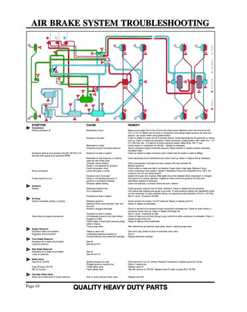
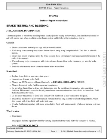
OverviewSection 2: The Charging System The charging system consists of: An air compressor, to pressurize the systemA governor, to control when the compressorneeds to build, or stop building, air for thesystem and also to control the air dryer purgecycleAn air dryer, to remove water and oil dropletsfrom the airReservoirs (or “air tanks”) to store air to be usedfor vehicle braking, etc. Safety valves to protect against excessivepressure in the system in the event that acharging system component malfunction occurs,e.g. a line blockageSingle check valves to maintain a one-wayflow of air into the reservoirs. This arrangementprotects the contents from being drained in theevent of an upstream loss of pressureLow pressure indicators to alert the driverwhenever a reservoir has less than a pre-setamount of air availableLow Pressure IndicatorSecondaryReservoirCheck ValveSafetyValveAir DryerCheck ValveGovernorPurgeValveSafety ValveAir CompressorDrain ValveBendix Air Co mpressorsThe air compressor is the source of energy for the airbrake system.Usually driven by the vehicle engine, the air compressorbuilds the air pressure for the air brake system. Theair compressor is typically cooled by the enginecoolant system and lubricated by the engine oil supply.(Certain models have self-lubricated and/or air-cooledversions available.) Note: Air compressor shafts canrotate in either direction.The vehicle’s compressor draws in filtered air, either atatmospheric pressure from the outside (or already atan increased pressure from the engine turbochargerwhere permitted), and compresses it until systempressure is achieved.6SupplyReservoirPrimaryReservoirNote: Although a typicalthree-reservoir system isshown here, some systemdesigns do not use aSupply reservoir.The brake system needs a supply of compressedair between a preset maximum and minimum. Thegovernor (along with a synchro valve for certainBendix air compressors) monitors the air pressure inthe supply reservoir and controls when the compressorneeds to pump air into the air system (also knownas the “air build cycle” - the compressor is “runningloaded”) and when the compressor can simply turnover without building pressure (“running unloaded”).When the air pressure becomes greater than that ofthe preset “cut-out”, the governor controls the unloadermechanism of the compressor, stops the compressorfrom building air, and causes the air dryer to purge.As the service reservoir air pressure drops to the“cut-in” setting of the governor, the governor returnsthe compressor back to building air and cycles the airdryer back to air drying mode.More info: visit www.bendix.com1-800-AIR-BRAKE (1-800-247-2725)
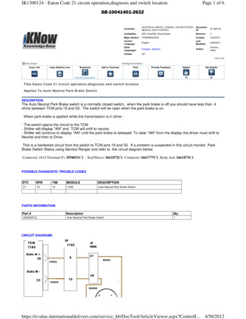
CompressorsAs the atmospheric air is compressed, all the watervapor originally in the air is carried along into the airsystem (as well as a small amount of the compressorlubricating oil) as vapor.The Duty Cycle is the ratio of time the compressorspends building air, relative to the total engine runningtime. Air compressors are designed to build air (run“loaded”) up to 25% of the time. Higher duty cyclescause conditions (such as higher compressor headtemperatures) that may adversely affect air brakecharging system performance. These conditions mayrequire additional maintenance due to a higher amountof oil vapor droplets being passed along into the airbrake system. Factors that add to the duty cycle are:air suspension, additional air accessories, use of anundersized compressor, frequent stops, excessiveleakage from fittings, connections, lines, chambers orvalves, etc. See page 9 for compressor maintenanceand usage guidelines. Use the Bendix BASIC test(p/n 5013711) where the amount of oil present in theair brake system is suspected to be above normal.The discharge line allows the air, water-vapor and oilvapor mixture to cool between the compressor and airdryer. The typical size of a vehicle’s discharge line,(see table on page 9) assumes a compressor witha normal (less than 25%) duty cycle, operating in atemperate climate. See Bendix and/or vehicle or airdryer manufacturer guidelines as needed.Air dryer inlet temperatures play a key role in airsystem cleanliness and air dryer performance. Whenthe temperature of the compressed air that entersthe air dryer is within the normal range, the air dryercan remove most of the charging system oil. If thetemperature of the compressed air is above thenormal range, oil as oil-vapor is able to pass throughthe air dryer and into the air system. Larger diameterdischarge lines and/or longer discharge line lengthscan help reduce the temperature.The discharge line must maintain a constant slopedown from the compressor to the air dryer inlet fittingto avoid low points where ice may form and block theflow. If, instead, ice blockages occur at the air dryerinlet, insulation may be added here, or if the inletfitting is a typical 90 degree fitting, it may be changedto a straight or 45 degree fitting to prevent moistureMore info: visit www.bendix.com1-800-AIR-BRAKE (1-800-247-2725)Discharge LineOptional Bendix PuraGuard QC OilCoalescing FilterAir rgeValveSupply ReservoirDrain Valvebuild-up and freezing. For more information on howto help prevent discharge line freeze-ups, see BendixBulletins TCH-08-21 and TCH-08-22. Conversely,shorter discharge line lengths or insulation may berequired in extreme cold climates to maintain properdryer operation.The air dryer contains a filter that collects oil droplets,and a desiccant bed that removes almost all of theremaining water vapor before the compressed air ispassed to the air brake service (supply) reservoir. Theoil droplets and the water collected are automaticallypurged at the dryer when the governor reaches its“cut-out” setting.For vehicles with accessories that are sensitive tosmall amounts of oil, we recommend installation,downstream of the air dryer, of a Bendix PuraGuard QC oil coalescing filter to further minimize the amountof oil present.See the Bendix Advanced Compressor Troubleshooting Guide (BW1971) or the compressor’s ServiceData sheet, available online at www.bendix.com formore information.7
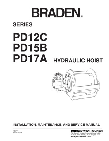
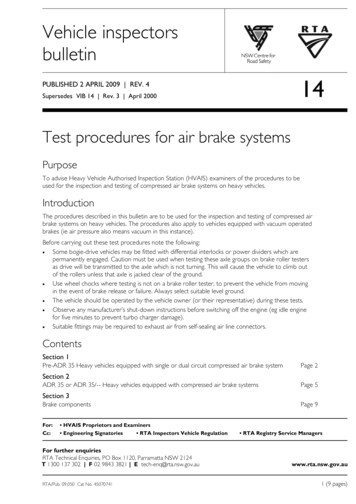
CompressorsSingle-Cylinder CompressorsTwo-Cylinder CompressorsBX-2150 aircompressorTu-Flo 700 aircompressorTu-Flo 501 aircompressorTu-Flo 500 aircompressorTu-Flo 400 aircompressorBA-921 aircompressorBA-922 air compressor(shown) or DuraFlo 596 air compressor (exteriorview is very similar)Four-Cylinder t lac12 em50 enC 0R tCylFPinde M Mrlu En sbr gic inat eed / seco W ava lfol atied er l.?av / aTuai irrblaobline?letoption?Tu-Flo 550 aircompressoror Tu-Flo 750 aircompressor(exterior viewis the same)Tu-Flo 400CompressorBX-2150 CompressorTu-Flo 500CompressorTu-Flo 501CompressorTu-Flo 550CompressorTu-Flo 700CompressorBA-921 CompressorTu-Flo 750CompressorTu-Flo 1000Compressor*DuraFlo 596 CompressorBA-922 CompressorTu-Flo g.WaterN31.62Eng.WaterN324Eng.WaterY***Tu-Flo 1000 aircompressor*Specialuse.e.g. Tanktrailerpump-offTu-Flo 1400 aircompressor**UsesInletCheckValve***Usesan InletRegulatingValveFor compressor Service Data Sheets,visit www.bendix.comMore info: visit www.bendix.com1-800-AIR-BRAKE (1-800-247-2725)
Compressor Maintenance GuidelinesMaintenance Schedule and UsageGuidelines2 Discharge Line LengthRegularly scheduled maintenance is the single mostimportant factor in maintaining the air brake chargingsystem. The table below is an introduction to themaintenance intervals for air brake charging systems.See your compressor and/or air dryer Service Datasheet for more information.If you are concerned that a compressor may bepassing oil, use the Bendix BASIC Test Kit: OrderBendix P/N 5013711.Low Air Usee.g. Line haul singletrailer without airsuspension, air overhydraulic brakes.Compressor with lessthan 15% duty cycle(builds air pressure 15% or less ofthe engine running time.)(5 or less axles)Medium AirUsee.g. Line haulsingle trailer withair suspension, RV,schoolbus.4 Air Dryer MaintenanceSchedule3ReservoirDraining1 Air Compressor Spec’dHigh Air Usee.g. Double/triple trailer,open highway coach,(most) pick-up & delivery,yard or terminal jockey,off-highway, construction,loggers, concrete mixer,dump truck, fire truck.Compressor with up to25% duty cycleCompressor with lessthan 25% duty cycleVery High AirUsee.g. City transit bus,refuse, bulk unloaders,low boys, urban regioncoach, central tireinflation.Compressor with up to25% duty cycle(builds air pressure 25% or less ofthe engine running time.)(5 or less axles)(8 or less axles)1 Examples of Typical Compressors Spec’da(12 or less axles)Bendix Tu-Flo 750 air compressorBendix BA-921 air compressorBendix BA-922 air compressorBendix Tu-Flo 550 air compressorDuraFlo 596 air compressorDischarge line:Discharge line:Discharge line:Discharge line:6 ft. @ ½ in. I.D.9 ft. @ ½ in. I.D.12 ft. @ ½ in. I.D.15 ft. @ 5/8 in. I.D.(oil carry-over control suggested (oil carry-over control suggested (oil carry-over control suggested (oil carry-over control suggestedupgradeb: 9ft. @ 5/8 in.)upgradeb: 12ft. @ 5/8 in.)upgradeb: 15 ft. @ 5/8 in.)upgradeb: 15 ft. @ ¾ in.)23Drain Reservoirs Every Month - 90 Days4Replace Air Dryer Cartridge Every 3 YearscOilPassingConcerns?Drain Reservoirs Every MonthReplace Every 2 YearscUse the BASIC Test Kit:Bendix P/N 5013711BASIC test acceptable range: 3 oil units per month.a. Note: Compressor and/or air dryer upgrades arerecommended in cases where duty cycle is greater thanthe normal range (for the examples above). For certainvehicles/applications, where turbo-charged inlet air isused, a smaller size compressor may be permissible.b. To counter above normal temperatures at the air dryerinlet, (and resultant oil-vapor passing upstream in the airsystem) replace the discharge line with one of a largerdiameter and/or longer length. This helps reduce theMore info: visit www.bendix.com1-800-AIR-BRAKE (1-800-247-2725)Replace Every YearcUse the BASIC Test Kit:Order Bendix P/N 5013711BASIC test acceptable range: 5 oil units per month.temperature of the discharged air. If sufficient coolingoccurs, the oil-vapor condenses and can be removed bythe air dryer. Discharge line upgrades are not coveredunder warranty. Note: To help prevent discharge linefreeze-ups, shorter discharge line lengths or insulationmay be required in cold climates. See Bendix BulletinsTCH-08-21 and TCH-08-22, for more information.c. With increased air demand the air dryer cartridge needsto be replaced more often.9
Governors and ComponentsGovernors and ComponentsThe Governor monitors the air pressure in the supplyreservoir and operates the compressor unloadingmechanism to control whether the compressor buildsair pressure or not.The Bendix D-2 governor is an adjustable pistontype valve available preset to a choice of pressuresettings. Note: The pressure range between the cutin and cut-out pressure is designed into the governorand is not adjustable. The D-2 governor may bedirect-mounted to the compressor or remote-mountedas desired. Specialized governors are available forvehicles needing a governor adapted to abnormallyhigh or low temperatures, as well as a “weatherproof”model.Exhaust PortGovernorsShown withbreathervalveinstalledD-2A GovernorD-2 GovernorThe D-2A governor is a non-adjustable version ofthe D-2 governor.D-2 /SV-1 GovernorModuleThe D-2 /SV-1 governor module is a specialcombination device used with the Bendix DuraFlo596 air compressor to provide the fast-rising unloadersignal needed by this compressor.Safety Valves are used in an air brake system toprotect against excessive air pressure buildup and tosound an audible alert. Safety valves are availablein both adjustable (e.g. the Bendix ST-1 valve) andnon-adjustable (e.g. ST-3 , ST-4 valve) styles, invarious pressure settings, and for various port sizes.Maximum service system air pressure allowed bygovernment regulation is typically 150 psi. Varioussafety valve settings are used at different points in thecharging and treatment system.Specifically designed for use in compressors, ST-4 safety valves are installed in an extra compressor headdischarge port, if available, or in the discharge line nearthe compressor, to prevent compressor damage in theevent of discharge line blockage.An Inlet Regulating Valve (or “IRV”) is typically usedon multi-cylinder compressors which receive their inputair supply from the pressurized side of the engineturbocharger. The IRV, which is generally mountedto the compressor inlet, is designed to regulatecompressor inlet pressure to 10 PSI or less. Theoutlet flange of the IRV can be mounted to all Bendix Tu-Flo compressors except the Bendix Tu-Flo 300compressor. The IRV may not be used in conjunctionwith single cylinder compressors.10ST-1 , ST- 3 and ST-4 Safety ValvesInletRegulatingValveInletCheckValvesInlet Check Valves (or “ICV”) are used on naturallyaspirated compressors to prevent oil mist from enteringthe inlet line during the unloaded cycle. The inletcheck valve either mounts to the intake side of thecompressor (and must be used in conjunction with aninlet valve stop or inlet adapter), or may be mountedremotely.More info: visit www.ben
2 More info: visit www.bendix.com 1800AIRBRAKE (18002472725) Device Index A18 Controller Assy. . 42 Actuators . . . . . . . . . . . . . 17 AD2 Air Dryer. 12 .