Transcription
Air Tractor Pilot Training Course-Series 402, 502, 504, 602November 2015By Steve Bailey, Cascade Aerial Services LLC
RevisionsRevision DatePages AffectedAir Tractor 402/502/504/602 Pilot Training Course2
This course is intended to serve as atraining aid to be accompanied by the AirTractor Flight Manuals sold with eachaircraft. All information contained hereinshould be verified against the approvedAFM.Air Tractor 402/502/504/602 Pilot Training Course3
Objectives1. Gain a basic understanding ofAir Tractor systems2. Become familiar with theaircraft’s Normal andEmergency Procedures3. Learn the performancelimitations of the individualmodelsAir Tractor 402/502/504/602 Pilot Training Course4
Course OutlineIntroductionSection 1: Aircraft SystemsSection 2: Normal OperationsSection 3: Emergency ProceduresSection 4: OperatingLimitations/PerformanceAir Tractor 402/502/504/602 Pilot Training Course5
IntroductionAir Tractor 402/502/504/602 Pilot Training Course6
IntroductionDue to the flexibility in the construction process of the Air Tractor there are several differentvariants of the airframes available, providing various sized hoppers for a variety of operationssuch as large vs. small fields. They have been produced for a few different roles, but aerialapplication for agriculture remains their primary mission. The 402 through 602 series aircraftshare very similar design and construction characteristics, with the most different one being the504 configured with a side by side 2 seat cockpit used for training purposes. For the purpose ofthis training program we will focus mainly on the single seat variants, but will cover the basiccontrol setup of the 2 seat 504. We’ll also touch on the differences between the models, butthe main subject matter will be on the systems they have in common.Following this program a pilot should be comfortable with describing and identifying thedifferent functions and parts associated with the aircraft that are pertinent to his mission andunderstanding. To simplify the material, when talking about similarities, we’ll just refer to themas “Air Tractors”. We’ll identify differences by specific model through descriptions and the useof graphs and charts.Air Tractor 402/502/504/602 Pilot Training Course7
IntroductionThe Air Tractor All metal cantilever low wingmonoplane designed especially foragricultural operations Extremely reliable Turbo Prop PT6 Rugged conventional gear setupallowing superior groundmaneuverability and unimproved stripoperationsAir Tractor 402/502/504/602 Pilot Training Course8
IntroductionThe Air Tractor Fiberglass hopperAIRCRAFTNOMINAL HOPPER CAPACITYAT-402400 US Gallons / 3250 lbsAT-502A/502B/504500 US Gallons / 4100 lbsAT-602600 US Gallons / 6500 lbsRemovable skin panels for ease of maintenance and cleaningCertified under a combination of FAR Part 23 and CAM 8: RestrictedCategory for Agricultural and Forest/Wildlife Conservation special purposesAIRCRAFTGWCAM 8 Max WeightCertified gross weights:402A7000 lbs7,860402B7000 lbs9,170502B8000 lbs9,400502A8000 lbs10,4805048000 lbs9,60060212500 lbsN/AAir Tractor 402/502/504/602 Pilot Training Course9
402602502504Air Tractor 402/502/504/602 Pilot Training Course10
Section 1Aircraft Systems Airframe construction Engine Propeller Fuel System Electrical Heating and Air Conditioning Flight Controls Dispersal Systems1-1Air Tractor 402/502/504/602 Pilot Training Course11
AirframeConstructionWings and TailFuselage Primarily 4130N weldedsteel tubing bridgingconstruction 2024-T3 Aluminum sheetingattached with camlocs Allows for ease of cleaning,maintenance, and field repair Mounted off of tubing frameto prevent trapped chemicalleading to corrosion1-2 Full cantilever wing with a NACA4415 airfoil 2024 T-3 Aluminumconstruction Tight rivet seams and heavy skinmake for burst resistantconstruction in the event of acrash All parts treated with Alodineand zinc chromateAir Tractor 402/502/504/602 Pilot Training Course12
AirframeConstructionFUSELAGE WINGS & TAILSealed rib baysmake a wet wingfuel systemConventional tailstructure with braceson lower sideAll fuselages areTIG welded byhand, primed,then coated withan epoxy paint1-3Air Tractor 402/502/504/602 Pilot Training Course13
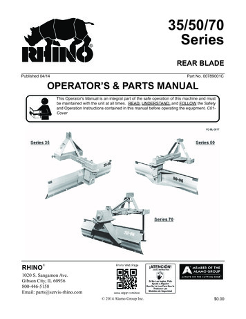
Airframe ConstructionLanding Gear Spring type landing gear: low drag, min. maintenance, highenergy absorption Main tires: 50-52 psi with Cleveland wheels and brakes Tail wheel: 60 psi 360 swivel, centering lock located left side of cockpitMain TireT/WAT-402A/B29x11-10 (10 Ply)5.00x5 (6 Ply)AT-502B/504/502A29x11-10 (10 Ply)5.00x5 (6 Ply)AT-60229x11-10 (10 Ply)17.5x6.25-6 (10 Ply) Brakes: Dual Cleveland, toe brakes, single reservoir (mountedon top of lower instrument panel) 5606A hydraulic fluid Parking brake applied by holding brake pressure, pulling parking brakelever, and releasing pedal pressure. Released by applying pedalpressure.1-4Air Tractor 402/502/504/602 Pilot Training CourseTailwheellocking pin14
AirframeConstructionBRAKE SYSTEMBrake System (504)Brake FluidReservoirClevelandDisc Brakes1-5Air Tractor 402/502/504/602 Pilot Training Course15
Before getting into the engine, just for clarification, various aircraft and enginemanufacturers use different terms to identify the same thing. Sometimes evendifferent models (from the same manufacturer) will use slightly differentterminology when describing essentially the same thing.Air Tractor AFM TermAlso used“Start Control”“Condition Lever”“Run” position“Ground Idle”, “Low Idle”“Flight Idle”“High Idle”Air Tractor 402/502/504/602 Pilot Training Course16
EngineGeneral PT6A Engine Pratt and Whitney PT6 Reverse flow free turbinedriving a gas generator and areduction box Multi stage axial, single stagecentrifugal compressor Engine options:1-6Air Tractor 402/502/504/602 Pilot Training Course17
Engine1-6General PT6A EngineAir Tractor 402/502/504/602 Pilot Training Course18
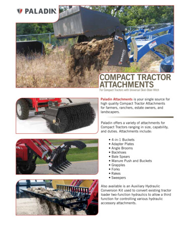
EngineGeneral PT6A EnginePropellerGovernorFuel ControlUnit (FCU)Air Intake(Plenum Coverremoved)Oil fill andDip StickFuel NozzlesExhaust PortOil Level Sitewindow(only on somemodels)1-7Air Tractor 402/502/504/602 Pilot Training Course19
EngineAccessory GearboxA/C Compressor, pulleysystem, and serpentinebeltStarter/Generator1-8Induction FilterPressure differentialswitchFuel Control Unit: Contains itsown internal fuel pump capableof providing fuel pressure toengine up to 10,000 ft (602 12,500 ft.)Aft ChipdetectionsensorEngine driven FuelPump (referred to as“airframe mounted”)P3 Filter (Compressor bleed air)Air Tractor 402/502/504/602 Pilot Training Course20
EngineOil SystemBlower fan installation on “large” PT-6 in the 502Aand 602Oil cooler blower motor: Providescooling to engine oil cooler whileengine is running with propfeathered on the ground.Each PT-6 has it’s own characteristics of where it likesit’s oil level to be. Some operators find that itmaintains a level between the 2 – 3 quart low markrather than the 1. Overfilling will result in a severemess in the engine compartment.1-9 All variants of the PT6carries 10 quarts (9.2 onthe smaller variants) ofoil Only 6.0 qts usable Recommend filling theengine to 1 quart belowmaximum when hot. On the large PT6 there isa spring loaded checkvalve to prevent oil loss inthe event the dipstick isnot installed, because ofthis, make sure to add oilslowly to prevent overfill.Air Tractor 402/502/504/602 Pilot Training CourseOil Cooler air intake located on leftside of engine cowling.Many operators will only conduct a full oil change duringthe aircraft annual. This is due to the fact that unlike apiston engine, the turbine oil is only used to lubricatebearings, not metal to metal contact such as piston ringsto a cylinder wall. This means the oil does not breakdown to the same degree as a piston engine.21
EngineOil SystemVenturi installation on “small” PT-6 in the 402,502, 504 The smaller PT6 installations of the 402, 502,504 etc. use a Venturi style blower. It extractscompressor bleed air from outside the POV (atlow power settings only) to drive the Venturi.At high power settings, the POV closes, andcooling air from outside is pushed across thecooler via the ram air scoop on the L/H side ofthe cowling.1-9Air Tractor 402/502/504/602 Pilot Training Course22
Engine1-9Oil SystemAir Tractor 402/502/504/602 Pilot Training Course23
EngineChip DetectionForward Chip detect sensor(bottom of Propeller Gearbox)Chip detection lightA Chip detect sensor is merely two small metal prongs spaced about 1/16 on an inch apart. When metallic debris passes between these it completes an electrical circuit thatilluminates the Chip detect light. Early in an engine’s life, under 500 hours, Chip lights may appear every now and then. This does not necessarily constitute an emergency.Most operators recommend just taking the plane home and notifying your mechanic. As the engine gains more time, then the light could become more serious. Continuedoperation is never recommended. (Not all Air Tractor’s are equipped with dual Chip detectors, some don’t have them on the accessory gearbox.)1-10Air Tractor 402/502/504/602 Pilot Training Course24
EngineInductionWhen flying through visiblemoisture always be aware ofoutside temperature. Inductionicing is something the Air Tractorwas not designed to handle andcan result in an engine suffocatingand flaming out. Some aircrafthave alternate air source on theback of the intake plenum to helpdeal with an induction blockage.Air intakeIf the alternate air source is used, realize that this isunfiltered, hot air being introduced into the engine. Thehigher heat will result in some loss of power and no airfilter can result in blade and bearing erosion over a longperiod of time. Also, anytime the cowling is removed thealternate air door should be checked for a good seal aroundthe edges to make sure warm air is not being introducedduring normal operations.Alternate airsource (backside ofplenum insidecowling)Alternate airsourcecontrolpushrodIntake Plenum with filter assemblyAir Filter LightThe Air Filter light will illuminate when the pressure differential across theplenum assembly exceeds design limitation. This can happen sometimes duringa high power takeoff if the conditions are right, this is normal. If the lightilluminates during normal operations, the air filter may be developing a blockageand maintenance should be notified.1-11Air Tractor 402/502/504/602 Pilot Training Course25
EngineEngine Controls Engine controls located on left side of cockpit Power, Prop, Start (Fuel) control levers connected to a series of pushrods(CAUTION: Damage may occur to linkage if Power lever moved to reverse while engine isnot running) Power: Normal forward operation; Reverse- depress Thumb Latch and pull lever aft Propeller: Forward high RPM; Full Aft Feather Start: Full Aft Cut-Off; Middle Low Idle (Ground); Forward High Idle (Taxi and Flightin order to avoid operating prop in yellow range) Starter, Generator, Igniter switches located on Lower Cockpit Panel, right handside Start switch spring loaded to OFF Ignitor Switch: Up ON (only when starter engaged)/ Center OFF / Down Continuous1-12Air Tractor 402/502/504/602 Pilot Training Course26
EngineEngine ControlsStarter Limitations: Motoring Maximum duration of 30 seconds followed by 1 minute of cool down. Can total 3 cycles, then must be allowed to cool for 30 minutes During engine start (per Air Tractor AFM) If ITT fails to rise within 10 seconds after moving the Start Control lever to the “Run”position, shut off fuel (pull Start Control lever to “C” stop) and release Start switch.Allow 30 seconds for fuel to drain plus 5 minutes for starter cool down. Conduct a15 sec dry motoring run and allow 10 minutes for starter cool down beforeattempting another start.1-13Air Tractor 402/502/504/602 Pilot Training Course27
Engine FCU Manual Override Red lever located on aft cockpitskin on pilot’s left hand side Used to modulate engine powerif Fuel Control Pneumatic Systemmalfunctions Intended for Emergency use onlyand MUST BE OFF for normaloperations In case of emergency the Powerlever must be in maximum forwardthrust position to enable manualmodulating of power via FCUmanual override lever1-14FCU overrideleverAir Tractor 402/502/504/602 Pilot Training CourseCAUTIONThe fuel control manualoverride does not duplicatethe normal fuel controlfunctions and is not to beused as an optional meansof controlling the engine. Itis intended for emergencyuse only. Using the manualoverride lever results inoverriding of all automaticcontrol features associatedwith the normal usage ofthe power control lever.28
EngineStart switchIgnitor RSTART1-15Battery switch(MASTER)Air Tractor 402/502/504/602 Pilot Training Course29
Propeller andGovernor Hartzell Constant Speed 3, 4, and 5 bladed propellers Aluminum 102”-115.2” diameter depending on engine Constant Speed with Reverse and Full Featheringcapability Woodward Over-speed Governor Engages 4% over primary governor in the event ofprimary failure Test function reduces rpm by 50 - 75( /- 60)1-16Air Tractor 402/502/504/602 Pilot Training Course30
Propeller andGovernorSpinnerback rweightsAir Tractor 402/502/504/602 Pilot Training CoursePropeller lowpitch stop31
Fuel System 2 wet wing tanks: 120 -290 gallons depending on model and options Optional additional wing tanks Both tanks feed into a common header tank Fuel valve: MAIN and OFF on left side of cockpit forward of throttle quadrant (cannot select individual tanks) 2 Fuel gauges (If equipped with MVP-50, all indications are on the one digital screen along with fuel flow) Note: Half a tank remaining is not half of the gauge 4 Gallons in each wing tank ungaugeable Strainers in each tank, main fuel filter located forward side of firewall Fuel Filter Warning light will illuminate in the event of a clogged firewall fuel filter (the is a bypass on this filter that willallow fuel to continue to the FCU, but if the FCU filter clogs, flameout can occur) Single electrical airframe mounted fuel pump and engine driven fuel pump both capable of delivering fuelto the fuel control pump at a minimum of 15 psi The engine driven pump operates continuously while the electrical boost pump is only used to pressurize the lines priorto starting and as a back-up to the engine driven boost pump. The Fuel Control Unit (FCU) has its own fuel pump as well that is capable of providing fuel to the engine withunrestricted operation up to 10,000 ft (402/502) and 12,500 ft (602) msl. Fueled via over wing fuel caps Optional single point refueling common on a lot of aircraft. Relocates fueling port to lower left aft side of fuselage.1-18Air Tractor 402/502/504/602 Pilot Training Course32
Fuel SystemLocated on lower left side offuselage.FIREWALLFuel FilterWarningLightNo longer used1-19Air Tractor 402/502/504/602 Pilot Training Course33
Fuel SystemFuel Selector ValveAirframemounted fuelboost pump(electrical)1-20Header tankAir Tractor 402/502/504/602 Pilot Training Course34
Electrical 24 volt 250 amp system 1-21Lucas 250-Amp 28-Volt starter generator (SG)Generator Control Unit (GCU) - mounted R/H side below cockpit floorLine Contractor Relay (LCR) – right side of firewallStart Relay – right side of firewallStart Switch – Lower instrument panelGenerator Switch – Lower instrument panelPilot’s Panel Voltmeter – Lower instrument panelLow Voltage Warning Light – Upper instrument panel15 amp GCU Circuit Breaker – Lower instrument panelAir Tractor 402/502/504/602 Pilot Training Course35
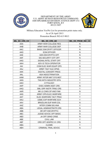
ElectricalPanel Layout will vary depending onmodel and owner preferenceFlightInstrumentsand HopperQuantityDisplayMVP 50EngineMonitoringSystemDispersal Monitoringsystem: displays hopperquantity and boompressureFuel Systemmonitoring andCaution/WarningLightsAC and Blower OperationUpper: Landing/Working LightsLower: Dispersal SystemUpper: FlightLights/Gyros/Flaps (CBs)Lower: Engine Operation1-22Air Tractor 402/502/504/602 Pilot Training Course36
ElectricalFlightInstrumentsand HopperQuantityDisplayMVP 50EngineMonitoringSystemDispersalMonitoring system:displays hopperquantity and boompressureFuel Systemmonitoring andCaution/WarningLights1-22AC andBlowerOperationAir Tractor 402/502/504/602 Pilot Training Course37
Electrical 2 Gill 24-volt batteries (63 amp-hrs) wired in parallel for high cranking power,mounted at the base of the firewall (502A -60AG/-65AG and 602 are 3 batterysystems) Ground start receptacle on lower left side of cowling Should be used if less than 24 volts in the batteries to prevent a hot startGround PowerReceptacleBattery Box drainvalve (Caution:Corrosive)24 Volt Gill Batteries1-23Air Tractor 402/502/504/602 Pilot Training Course38
Air Conditioning Gas-cycle system allows for outside ram air,re-circulated cockpit air, or a combination Ram-air lever: aft wall of cockpit, right sideIf runningrecirculating air;Fresh Air lever – OFF,Cockpit Air Door OPEN The air conditioner compressor is enginedriven from a splined drive pad on theaccessory gear box (AGB). A machined brassquill shaft (designed as a shear point in theevent of compressor failure) connects theAir Conditioningengine AGB to the compressor drive belt.The quill shaft will fail in torsion, preventing Drive Pulley andthe failure loads from being transmitted into Serpentine Beltthe engine AGB.If while running the air conditioning for an extended period of timeyou start to notice the air temperature increasing, turn of the A/Cbecause the evaporator coil has started to freeze up (often caused bythe cockpit recirc door either not open, or blocked). Allow it to warmup and thaw out, then continue normal operation.1-24Machined brass quillshaftAir Tractor 402/502/504/602 Pilot Training Course39
Air Conditioning Air Conditioning master switch (BLOWER ONLY/OFF/AIR COND.):allows for blower forced air circulation without air conditioning Blower Switch (HIGH/MED/LOW): blower is ON anytime the A/CSwitch is not OFFA/C SwitchUP – Blower Fan only (ambient air)CENTER – OFFDOWN – Air Condition (Cool air being supplied fromcompressor on engine accessory case)Fan Operation:Basic Low, Medium, and Hi speeds1-25Air Tractor 402/502/504/602 Pilot Training Course40
Heating Bleed air off compressor section of the turbine routed to an ON-OFFvalve on the left-hand side of the fuselage just forward of the cockpit. Actuated by pulling a cable on the left side of the pilot’s seat.Be advised, the bleed air can get very hot in this aircraft if left unattended. It has been known to melt plastic parts when operated at full power.Bleed Air off of compressorBleed Air muffler under leftside of cockpit floorboards.Diffusor in cockpit floor.Vernier type control knob1-26Air Tractor 402/502/504/602 Pilot Training Course41
Flight Controls Ailerons and Elevator: push-pull tubes through bell cranks to thecontrol surface Rudder: stainless steel cables Flaps: Fowler type electrically driven by jack screw to a torque tube Can be stopped anywhere between 0 and 30 degrees of travelControlled by toggle switch mounted just aft of throttle quadrant10 deg increment markings on left wing appear as flaps are extendedOn 402, 502, and 602 series, the ailerons droop with the flapsThe flap motor goes through a lot of heavy operation on Air Tractors. So be aware of when your flaps reach a fully retracted position anddon’t try to continue to operate them beyond that. A limit switch is installed to stop them at full up, but if this fails or is set slightlywrong can could be applying a high amount of increased stress on the flap torque tubes.1-27Air Tractor 402/502/504/602 Pilot Training Course42
Flight ControlsFowler style Flaps withincrement marking on leftflap. (small fiberglass fairingcontains a light for nightillumination)Large spanailerons withcontrol assistservo tabsprovide goodroll control.1-28Air Tractor 402/502/504/602 Pilot Training CourseConventionalrudder andelevator controls43
Flight ControlsTrimPitch TrimRoll TrimYaw TrimAT-402A/BCockpit controlledleverGround adjustable –bendable tabsGround adjustable –hinged tab andpushrodAT-502B & 504Cockpit controlledleverGround adjustable –bendable tabsGround adjustable –hinged tab andpushrodAT-502A, 502XPCockpit controlledleverGround adjustable –bendable tabsCockpit controlled wheelAT-602Cockpit controlledleverCockpit controlled,electric servo tab(L/H) and bendabletab (R/H)Cockpit controlled wheel1-29Air Tractor 402/502/504/602 Pilot Training Course44
Rinse and SmokeDispersal Systems Rinse System: 18 gallon tank mounted forward ofthe firewall on the top side of the engine mount.Used to rinse chemical out of the hopper afteruse. Controlled by spring loaded switch on lowerleft instrument panel. Smoke System: 2 gallon tank with electric pumpmotor on the box Smoke oil tank located just aft of cockpit on left side. Fillport is on the left side of fuselage just aft of the door at thebase of the cockpit canopy. Total quantity is approximately 2 gallons and is pumped intothe right exhaust stack Activation is via a press and hold button on the controlstick.1-33Air Tractor 402/502/504/602 Pilot Training Course45
Dispersal Systems400 – 600 Gallon single piecefiberglass hopper depending onmodelAgriculturalHopper quantitygaugeAir tight lid with overcenter latches1-34Air Tractor 402/502/504/602 Pilot Training Course46
AgriculturalDispersal Systems Components 2.5 in. stainless or aluminum plumbing and streamlined extruded stainless oraluminum booms 48 nozzles (drilled and tapped for an additional 48 if desired) Spray Pump; Agrinuatics 3 in. capacity Fan: Lane Electric Brake (Weath-Aero, a less common option) Control Valve Strainer Gate Box Hopper Vent Flow Meter1-35Air Tractor 402/502/504/602 Pilot Training Course47
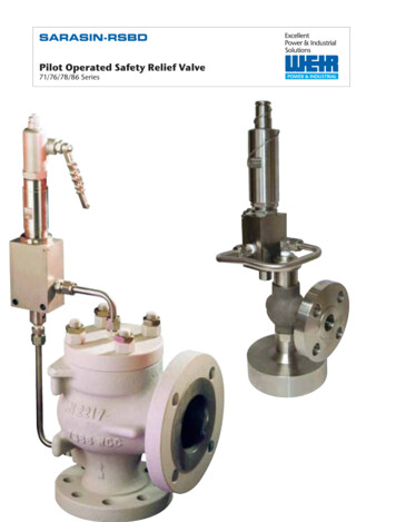
Dispersal SystemsAgriculturalHopper Vent(Open end points aft for wetchemical, forward for dry)Dual filler ports (optional,common setup is just one)Spray PumpHopper Gate BoxSpray Nozzle1-36Air Tractor 402/502/504/602 Pilot Training Course48
Dispersal SystemsAgriculturalLane Elect Pump Brake andFanControl Valve andspray handle(“money handle”)for normal sprayoperationEmergencyDump Gate1-37Air Tractor 402/502/504/602 Pilot Training Course49
Dispersal SystemsAgricultural Switching from liquid to dry material Remove only the pump and booms For extended fertilizer use, the center boom assembly and control valve should beremoved to prevent fertilizer from getting into the valve assembly Can be accomplished in a few minutes by removing stainless T-pins that support the centerboom assembly and removing the bolts that attach the valve to the stainless bracket The hopper vent tube is welded 3” stainless steel tubing inside the hopper. The vent tube protruding from the side of the adapter box is aluminum and pointsbackwards when liquid material is being used, the slight negative pressure preventsfumes from escaping around the lid. It must be rotated forward to provide positivepressure inside the hopper when dry material is used. This allows for a smaller gateopening for a given poundage which reduces the blockage effects of the door openinginto the slipstream. Various optional spreaders and gateboxes are available1-38Air Tractor 402/502/504/602 Pilot Training Course50
LightingAircraft Systems Exterior Lights Dual taxi/nose lights on engine cowling, Nav andAnti Collision lights on wingtips Retractable forward facing landing lights Work Lights Detachable turn lights (must beattached/detached prior to flight)Upper: Landing/ Working LightsLower: Dispersal System(May also be attached to a small toggle switch on the controlstick)1-39Air Tractor 402/502/504/602 Pilot Training Course51
Aircraft Systems Airframe construction Engine Propeller Fuel System Electrical Heating and Air Conditioning Flight Controls Dispersal Systems LightingAir Tractor 402/502/504/602 Pilot Training Course52
Section 2NORMAL OPERATIONS Preflight Inspection Before Engine Starting Engine Start (Battery) Before Taxi Before Takeoff (Runup) Takeoff Climb2-1 CruiseDescentBefore LandingApproachBalked LandingShutdown and SecuringAir Tractor 402/502/504/602 Pilot Training Course53
NORMAL OPERATIONSPreflight InspectionCockpit Check1)2)3)4)5)6)7)8)2-2Control Lock - STOWParking Brake – OFF (Take terrain into account)Battery – ONVoltmeter – 24 Volts min for battery startFuel Quantity Gauges – CheckFlaps – EXTENDBattery – OFFPower, Prop, Start Levers - AFTAir Tractor 402/502/504/602 Pilot Training Course54
NORMAL OPERATIONSPreflight InspectionExterior Check1) Baggage Door – CLOSED and FASTENED2) Booms, Spray Nozzles, and Fittings – CHECK for leaksand secure3) Flaps – CHECK secure4) Aileron – CHECK secure, no slop, servo arm movesopposite of aileron, and trim tab secure5) Wing Tip – NO Damage, NAV/Anti Collision lights secure,turning light fully stowed6) Fuel Vent Tube – Clear no obstructions7) Pitot Tube – Lift cover and check clear8) L/H Fuel Cap – Visually check secure9) Left Wing Fuel Sump – Drain and check for debris/water10) Header Tank Sump – Drain and check for debris/water2-3Air Tractor 402/502/504/602 Pilot Training Course55
NORMAL OPERATIONSPreflight InspectionExterior Check (Drain locations 402)2-3Air Tractor 402/502/504/602 Pilot Training Course56
NORMAL OPERATIONSPreflight InspectionExterior Check (Drain locations 502)2-3Air Tractor 402/502/504/602 Pilot Training Course57
NORMAL OPERATIONSPreflight InspectionExterior Check (Drain locations 602)2-3Air Tractor 402/502/504/602 Pilot Training Course58
NORMAL OPERATIONSPreflight InspectionExterior Check11) Spray Plumbing – Check for leaks and loose connections12) Left Hand Gear Leg - Inspect for cracks, damage, stressmarks- Optional Wire cutters may be installed on leading edge of gearleg check secure13) Left Wheel and Brake assembly – Check no chords showingon tire, inflated to 62 PSI, brake pads are free to moveslightly14) Oil Service Door on top Cowl – Check oil level not morethan 2 quarts below “Full” mark. Cap secure.15) Prop – Remove tether and rotate briskly while listening forunusual rubbing or metallic noise2-4Air Tractor 402/502/504/602 Pilot Training Course59
NORMAL OPERATIONSPreflight InspectionExterior Check16)17)18)19)Cowling – Check for any unfastened CamlocsAir Intake – Check for foreign objectsExhaust Stacks – Remove coversRight Hand Gear Leg - Inspect for cracks, damage, stressmarks- Optional Wire cutters may be installed on leading edge ofgear leg – check secure20) Right Wheel and Brake assembly – Check no chordsshowing on tire, inflated to 62 PSI, brake pads are free tomove slightly21) Right Wing Fuel Sump – Drain and check for debri/water22) R/H Fuel Cap – Visually check secure23) Fuel Vent Tube – Clear no obstructions24) Wing Tip – NO Damage, NAV/Anti Collision lights secure,turning light fully stowed2-5Air Tractor 402/502/504/602 Pilot Training Course60
NORMAL OPERATIONSPreflight InspectionExterior Check25) Aileron – CHECK secure, no slop, servo arm moves oppositeof aileron.26) Flaps – CHECK secure27) Booms, Spray Nozzles, and Fittings – CHECK for leaks andsecure28) Right Hand Side of Fuselage – Check skins for unfastenedCamlocs29) Static Port – Clear of obstructions30) Right Hand Stabilizer and Strut – Check secure, should be noplay in any direction31) Right Hand Elevator – Check hinge bolts, move up anddown, check for security32) Trim Tabs – Check for security, inspect linkage2-6Air Tractor 402/502/504/602 Pilot Training Course61
NORMAL OPERATIONSPreflight InspectionExterior Check33) Rudder – Start from top down, inspect hinge bolts, movefrom stop to stop to check security, inspect rudder cablesand connections34) Tail Wheel Assembly – Check attach points to fuselage1)2)3)4)Inspect Tailwheel ForkCheck for broken centering springsCheck tailwheel lock by lifting plunger by handTire inflation to 60 PSI35) Left Hand Elevator – Check hinge bolts, move up and down,check for security36) Left Hand Stabilizer and Strut – Check secure, should be noplay in any direction37) Static Port – Clear of obstructions38) Left Hand Side of Fuselage – Check skins for unfastenedCamlocs2-7Air Tractor 402/502/504/602 Pilot Training Course62
NORMAL OPERATIONSPreflight InspectionExterior Check39) Tie down Ropes – All removed and wheel chocks out40) Hopper Lid – Closed, latches secure41) Front Wind Screen – Clear and wiper secure2-8Air Tractor 402/502/504/602 Pilot Training Course63
NORMAL OPERATIONSBefore Engine StartingBefore Start1)2)3)4)5)6)7)8)9)10)11)12)13)2-9Fire Extinguisher – SecureCockpit – No loose itemsSeat Belts and Harness – FASTEN and SecureBrakes – Test and set parking brake ON (Depress pedals and pull lever)Trim – Elevator and Rudder set to Green ArcAltimeter – SETRudder Pedals – SET (Make sure able to achieve full deflection)Flight Controls – CHECK FREE and CLEARCircuit Breakers – Check all INBattery Switch – ONFuel Selector Valve – ONFuel Boost Pump - ON (Until 5 psi min. fuel pressure noted) OFFFlaps – RETRACT (can be delayed till after start to avoid battery drain)Air Tractor 402/502/504/602 Pilot Training Course64
NORMAL OPERATIONSBefore Engine StartingBefore Start14)15)16)17)2-10Fuel Flow Meter – SETWarning / Caution Lights – Push to TESTVoltmeter – CHECK 24 volts min.FCU Over-ride – Check Secure (if installed)Air Tractor 402/502/504/602 Pilot Training Course65
NORMAL OPERATIONSEngine Start (Battery)Starting1)2)3)4)5)6)7)8)9)10)Power lever – IDLE STOPProp Lever – FULL AFT to Feather Stop (F)Start Control Lever (Condition) – FULL AFT to Fuel Cut-OffBattery Switch – ONIgnition Switch – OFF (Center Positon)Generator Switch – OFFProp Overspeed Switch – OFFProp Area – CLEARSta
on top of lower instrument panel) 5606A hydraulic fluid Parking brake applied by holding brake pressure, pulling parking brake lever, and releasing pedal pressure. Released by applying pedal pressure. 14 Tailwheel locking pin Airframe Construction 1-4 Air Tractor 402/502/504/602 Pilot Training Course Main Tire T/W AT-402A/B 29x11-10 (10 Ply) 5.00x5 (6 Ply) AT-502B/504/502A 29x11-10 (10 Ply .