Transcription
SERIESPD12CPD15BPD17AHYDRAULIC HOISTINSTALLATION, MAINTENANCE, AND SERVICE MANUALLIT2103 R44-2010PRINTED IN U.S.A.1
Table of ContentsGENERAL SAFETY RECOMMENDATIONS . 4THEORY OF OPERATION . 5HOIST INSTALLATION. 7RECOMMENDED FASTENER TORQUE . 9WIRE AND BRAIDED ROPE INSTALLATION . 9TWO SPEED MOTOR CASE DRAIN PLUMBING . 10PREVENTIVE MAINTENANCE. 10RECOMMENDED OIL CHANGE INFORMATION. 11TROUBLE SHOOTING . 12HOIST DISASSEMBLY. 16EXPLODED VIEW DRAWING AND PARTS KEY .18-19PLANET CARRIER SERVICE . 20MOTOR SUPPORT – BRAKE CYLINDER SERVICE . 22BRAKE CLUTCH SERVICE . 26HOIST ASSEMBLY . 28BRAKE VALVE SERVICE. 32REVERSING DIRECTION OF DRUM ROTATION . 34PD17A ROTATION INDICATION PROXIMITY SENSOR . 362
FOREWORDRead this entire publication and retain it for future reference.If you have any questions regarding your Braden Planetary Hoist or this publication, call the Braden Service Department at 1-918-251-8511, 08:00-1630 hours, CT, Monday through Friday.The minimum service intervals specified are for operating hours of the prime mover.The following service instructions have been prepared to provide assembly, disassembly and maintenance information for the BRADEN Model PD12C, PD15B and PD17A series hoist. It is suggested that before doing any work onthese units, all assembly and disassembly instructions should be read and understood.Some pictures in this manual may show details or attachments that are different from your hoist. Also, some components have been removed for illustrative purposes. Illustrations and pictures in this manual are of a “typical” unit soldthrough our distribution channels. Some hoists, particularly those sold directly to original equipment manufacturers(OEM), may differ in appearance and options.Whenever a question arises regarding your BRADEN HOIST, please contact BRADEN Service Department for thelatest available information.Serial Numbers and Model Numbers are located tothe left hand side of the hydraulic motor, stampedinto the base. Always refer to the Serial Number andModel Number when requesting information or service parts.EXPLANATION OF MODEL NUMBERPD12C29064 - 02 - U - L - D12C2906402UL1DRUMOPTIONROTATIONBASEDESIGNATES POWER DRUMDESIGNATES 12,000 LB. APPROXIMATE FIRST LAYER LINE PULLDESIGNATES THE MODEL SERIES RELATING TO DESIGN CHANGESDESIGNATES TOTAL GEAR REDUCTION (OTHER RATIOS INCLUDE 21, 41, 59, 34, ETC.)DESIGNATES HYDRAULIC MOTOR DISPLACEMENT IN CU. IN/REV(DECIMAL POINT ELIMINATED. EXAMPLE 064 6.4 CU IN/REV)DESIGNATES THE DRUM OPTION (OTHER DRUMS INCLUDE 01, 04, 05, 23G, ETC.)DESIGNATES UNDERWOUND CABLE DRUM - OPTIONALDESIGNATES LEFT HAND BASE - OPTIONAL, BLANK IS STANDARD RIGHT HAND BASEPERMITS TESTING AND INSPECTION PER API 2C FOR OFFSHORE CRANES - OPTIONAL3OPTION
GENERAL SAFETY RECOMMENDATIONSSafety and informational callouts used in this manual include:!! WARNING !CAUTION !CAUTION – This emblem is used to warn againstpotential or unsafe practices which COULD resultin personal injury and product or property damage ifproper procedures are not followed.WARNING – This emblem is used to warn againsthazards and unsafe practice which COULD result insevere personal injury or death if proper proceduresare not followed.Safety for operators and ground personnel is of prime concern. Always take the necessary precautions to ensuresafety to others as well as yourself. To ensure safety, the prime mover and hoist must be operated with care andconcern by the operator for the equipment and a thorough knowledge of the machine’s performance capabilities.The following recommendations are offered as a general safety guide. Local rules and regulations will also apply.1. Be certain equipment (boom, sheave blocks, pendants, etc.) is either lowered to the ground orblocked securely before servicing, adjusting, or repairing hoist.16. Do not use knots to secure or attach wire rope.17. The BRADEN designed wire rope anchors are capable of supporting the rated load when installedproperly. For additional safety, ALWAYS maintaina minimum of five (5) wraps of wire rope on thedrum.2. Be sure personnel are clear of work area BEFOREoperating hoist.3. Read all warning and caution tag information provided for safe operation and service of hoist.18. Never attempt to clean, oil or perform any maintenance on a machine with the engine or prime moverrunning, unless instructed to do so in this manual.4. Inspect rigging and hoist at the beginning of eachwork shift. Defects should be corrected immediately.19. Never operate hoist controls unless you are properly positioned at the operators station and you aresure personnel are clear of the work area.5. Keep equipment in good operating condition. Performscheduled servicing and adjustments listed in the“Preventive Maintenance” section of this manual.20.Assure that personnel who are responsible for handsignals are clearly visible and that the signals to beused are thoroughly understood by everyone.6. An equipment warm-up procedure is recommendedfor all start-ups and essential at ambient temperatures below 40 F (4 C). Refer to “Warm-up Procedure” listed in the “Preventive Maintenance” sectionof this manual.21.Ground personnel should stay in view of the operator and clear of hoist drum. Do not allow ground personnel near hoist line under tension. A safe distanceof at least 1-1/2 times the length of the cable shouldbe maintained.7. Operate hoist line speeds to match job conditions.22. Do not exceed the maximum pressure, PSI (kPa),or flow, GPM (LPM), stated in the hoist specifications.8. Leather gloves should be used when handling wirerope.9. Never attempt to handle wire rope when the hookend is not free. Keep all parts of body and clothingclear of cable rollers, cable entry area of fairleadsand hoist drum.23. Install guarding to prevent personnel from getting any part of body or clothing caught at a pointwhere the cable is wrapped onto the drum or drawnthrough guide rollers.10. When winding wire rope on the hoist drum, neverattempt to maintain tension by allowing wire rope toslip through hands. Always use “Hand-Over-Hand”technique.24. “Deadman” controls, which automatically shut offpower to the hoist whenever the operator leaves hisstation, should be installed whenever practicable.11. Never use wire rope with broken strands. Replacewire rope.25. Never allow anyone to stand under a suspendedload.12. Do not weld on any part of the hoist.26. Avoid sudden “shock” loads or attempting to “jerk”load free. This type of operation may cause heavyloads, in excess of rated capacity, which may resultin failure of cable and hoist.13.Use recommended hydraulic oil and gear lubricant.14. Keep hydraulic system clean and free from contamination at all times.15. Use correct anchor for wire rope and pocket indrum.4
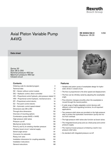
THEORY OF OPERATIONDESCRIPTION OF HOISTThe hoist has four basic component parts:The static brake system has three operating components:1. Spring Applied, Multiple Friction Disc Static Brake2. Overrunning Brake Clutch Assembly3. Hydraulic Piston and Cylinder1. Hoist base2. Hydraulic motor and brake valve3. Brake cylinder and motor support4. Drum assemblyThe drum assembly consists of three basic assemblies:1. Drum with integral ring gear2. Output planetary gear set3. Primary planetary gear setFigure 1HOISTINGThe hydraulic motor is bolted to the motor support whichin turn is bolted to the brake cylinder and the base. Themotor end of the drum, running on a ball bearing, issupported by the brake cylinder. The other end of thedrum runs on a ball bearing on the support bolted to thebase. The ring gear for both planetary sets is machinedinto the drum’s inside surface.Static BrakeMotorBrake ValveTo TankHOIST OPERATIONThe hydraulic motor drives the sun gear of the primaryplanetary gear set through the splined inner race of theoverrunning brake clutch. When driven by the sun gear,the primary planet gears walk around the ring gear inthe drum and drive the primary planet carrier.PumpControl ValveLowPressureThe primary planet carrier drives the output planetsun gear which, in turn drives the output planet gears.The output planet carrier is splined to the bearing support and cannot rotate. Therefore, as the output planetgears are driven by the sun gear, they will drive the ringgear/drum.HighPressureMediumPressureFigure 2DUAL BRAKE SYSTEM - DESCRIPTIONLOWERING 1The dual brake system consists of a dynamic brakesystem and a static brake system.The dynamic brake system has two operating components:1. Brake valve assembly2. Hydraulic motorThe brake valve is basically a counterbalance valvewith good metering characteristics. It contains a checkvalve to allow free flow of oil to the motor in the hoisting direction and a pilot operated, spring-loaded spoolvalve that blocks the flow of oil out of the motor whenthe control valve is placed in neutral. When the controlvalve is placed in the lowering position, the spool valveremains closed until sufficient pilot pressure is appliedto the end of the spool to shift it against spring pressure and open a passage. After the spool valve cracksopen, the pilot pressure becomes flow-dependent andmodulates the spool valve opening which controls thelowering speed. Refer to figures 1, 2, and 3.Figures 1, 2, and 3.Static BrakeMotorBrake ValveTo TankPumpControl ValveLowPressure5MediumPressureHighPressure
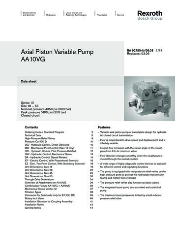
determine the amount of oil that can flow through it andthe speed at which the load will be lowered. Increasingthe flow of oil to the----- motor will cause the pressureto rise and the opening in the brake valve to enlarge,speeding up the descent of the load. Decreasing thisflow causes the pressure to lower and the opening inthe brake valve to decrease thus slowing the descentof the load.Figure 3LOWERING 2Static BrakeMotorBrake ValveWhen the control valve is shifted to neutral, the pressure will drop and the brake valve will close, stoppingthe load. The friction brake will engage and hold theload after the brake valve has closed.To TankWhen lowering a load very slowly for precise positioning, no oil flow actually occurs through the hoist motor.The pressure will build up to a point where the brake willrelease sufficiently to allow the load to rotate the motorthrough its own internal leakage. This feature results ina very slow speed and extremely accurate positioning.PumpControl ValveLowPressureMediumPressureHighPressureThe friction brake receives very little wear in the lowering operation. All of the heat generated by the loweringand stopping of a load is absorbed by the hydraulic oilwhere it can be readily dissipated.The static brake is released by the brake valve pilotpressure at a pressure lower than that required to openthe pilot operated spool valve. This sequence assuresthat dynamic braking takes place in the brake valve andthat little, if any, heat is absorbed by the friction brake.The friction brake is a load holding brake only and hasnothing to do with dynamic braking or rate of descentof a load.Figure 4Sprag CamsStatic Friction Brake AppliedThe overrunning brake clutch is splined to the primarysun gear shaft between the motor and the primary sungear. It will allow this shaft to turn freely in the directionto raise a load and lock up to force the brake discs toturn with the shaft in the direction to lower a load. Referto figures 4 and 5.The hydraulic cylinder, when pressurized, will releasethe spring pressure on the brake discs, allowing thebrake discs to turn freely.Permits free shaft rotationwhile hoistingDual Brake System – OperationWhen hoisting a load, the brake clutch which connectsthe motor shaft to the primary sun gear, allows free rotation. The sprag cams lay over and permit the inner raceto turn free of the outer race. Figure 4. The friction brakeremains fully engaged. The hoist, in raising a load, isnot affected by any braking action. Figure 1.Figure 5Sprag CamsStatic Friction Brake AppliedWhen the lifting operation is stopped, the load attemptsto turn the primary sun gear in the opposite direction.This reversed input causes the sprag cams to instantlyroll upward and firmly lock the shaft to the fully engagedfriction brake. Figure 5.When the hoist is powered in reverse, to lower the load,the motor cannot rotate until sufficient pilot pressure ispresent to open the brake valve. Figures 2 & 3. Thefriction brake within the hoist will completely release ata pressure lower than that required to open the brakevalve. The extent to which the brake valve opens willLoad attempts to rotate shaft in opposite directionBrake clutch locks sun gear shaft to friction brake6
HOIST INSTALLATION1. The hoist should be mounted with the centerline ofthe drum in a horizontal position. The mounting planeof the base may be rotated in any position around thiscenterline.HOISVENT PLUGABOVE CENTERLINETCenterLine4. The vent plug must always be located above the horizontal centerline. If the hoist is mounted on a pivotingsurface, be sure vent plug remains above the centerlinein all positions. If necessary, reposition bearing supportand vent plug as follows:SIONSBROKEU.S.A.4012This hoist mBRADEN GearmaticSERIAL NO.er76381HOISA. Remove bearing support bolts.B. Rotate bearing support until vent plugis positioned correctly and bolt holesare aligned.C. Evenly tighten bolts to recommendedtorque.T5. Hydraulic lines and components that operate thehoist must be of sufficient size to assure minimum backpressure at the hoist motor ports. The hydraulic backpressure measured at the motor work ports must beless than 100 PSI (690 kPa) at full operating flow. Backpressure in excess of 100 PSI (690 kPa) will shortenmotor shaft seal life and partially release the load holding brake. The standard hoist is supplied with the gearmotor internally drained and connected the drain bypass port on the Braden brake valve. If high back-pressures are encountered, the motor should be externallydrained directly to the reservoir and the “DRAIN” porton the brake valve capped. All piston motors MUST bedrained directly to the reservoir. The piston motor casedrain port must NEVER be exposed to more than 42PSI (290 kPa); shaft seal damage will occur.WINCH DIVISIONSBROKEN ARROW,OK.,74012U.S.A.This hoist must be maintained perBRADEN Gearmatic Service Manual.SERIAL NO.763812. Because of the design of the mounting base, the direction of line pull should only be as shown in the aboveillustration. Line pulls in any other direction must be approved by BRADEN Engineering.3. When mounting the hoist, use all eight (8) mounting holes and grade 8 capscrews and nuts. Tighten torecommended torque.It is important that the hoist is mounted on a surfacethat will not flex when in use, and cause binding of thegear train. Binding in the gear train will result in accelerated wear and heat. Also, be sure the hoist is mountedon a flat surface. If necessary, use shim stock to insurethe mounting surface is flat within 0.020 in. (0.5 mm).Use stainless steel shim stock as required.6. The hoist should be mounted perpendicular to animaginary line from the center of the drum to the firstsheave to insure even spooling. Make certain the fleetangle does not exceed 1-1/2 degrees.FLEET ANGLETO LOADORFIRST SHEAVEA1/2 O1 1/2 OMINMAXBA B7
HOIST ASSEMBLYW/BRAKE VALVE& STATIC BRAKEWINCH ASSEMBLYW/BRAKE VALVE& STATIC BRAKEBRAKEVALVETPHOIST BRAKEBRAKEVALVEBRWINCH LVALVEPUMPPUMPOil having 150 to 330 SUS (30-60 cSt) viscosity at 104 F(40 C) and viscosity index of 100 or greater will givegood results under normal temperature conditions. Theuse of an oil having a high viscosity index will minimizecold-start trouble and reduce the length of warm-up periods. A high viscosity index will minimize changes inviscosity with corresponding changes in temperature.! WARNING !DO NOT use a control valve with any detents orlatching mechanism that would hold the control valvein an actuated or running position when the operatorreleases the control handle. Use of the wrong typeof control valve could lead to unintentional operationof the hoist, which could result in property damage,personal injury, or death.Maximum cold weather start-up viscosity should notexceed 5000 SUS (1000cSt) with a pour point at least20 F (11 C) lower than the minimum temperature.Under continuous operating conditions the temperatureof the oil at any point in the system must not exceed180 (82 C). Optimum oil temperature is generally considered to be 120-140 F (49-60 C).In general terms; for continuous operation at ambienttemperatures between 50 and 110 F (10 to 43 C) useISO 46; for continuous operation between 10 and 90 F(-12 to 32 C) use ISO 32; for applications colder than10 F (-12 C), contact the BRADEN Service Department. The use of multi-viscosity oils is generally notrecommended.The directional control valve must be a three position,four- way valve without detents and with a spring centered motor spool such that the valve returns to thecentered position whenever the handle is released, andboth work ports are open to tank (open center, openport).8. The hydraulic oil filter should have a 10 micron nominal rating and be full flow type and meet the requirements of the hydraulic pump manufacturer.7. High quality hydraulic oil is essential for satisfactoryperformance and long hydraulic system componentlife.8
RECOMMENDED FASTENER TORQUEHigher or lower torques for special applications will be specified such as the use of spanner nuts, nuts on shaftends, jam nuts and where distortion of parts or gaskets is critical.Lubricated torque values based on use of SAE 30wt engine oil applied to threads and face of bolt or nut.Avoid using thread lubricants (such as anti-seize compound) as the applied torque may vary by 10 - 40%, depending upon the product used.7RUTXH /% )7 1 P7RUTXH /% )7 1 P%ROW 'LDP ,QFKHV7KUHDG SHU LQFK%ROW 'LDP ,QFKHV7KUHDG SHU LQFK'U\/XEHG'U\/XEHG'U\/XEHG'U\ /XEHG *UDGH *UDGH *UDGH *UDGH 7R FRQYHUW /% )7 WR .J P PXOWLSO\ /% )7 YDOXH E\ WIRE AND BRAIDED ROPE INSTALLATIONANCHORING WIRE ROPEANCHORING BRAIDED ROPEEarly StyleWire RopeAnchorTake the free end of the wire rope and insert it throughthe small opening of the anchor pocket. Loop the wirerope and push the free end about half of the way backthrough the pocket. Install the wedge, then pull the slackout of the wire rope. The wedge will slip into the pocketand secure the wire rope into the drum. The early styleanchor wedge is designed to accommodate several different sizes of wire rope. You may anchor 7/16 and 1/2in. (11 & 13 mm) wire rope by inserting the wedge, largeend first. Anchor 9/16 and 5/8 in. (14 & 16 mm) wirerope by inserting the wedge, small end first.A special wedge is used to anchor 1 and 1 1/8 in. (25& 28 m) braided synthetic rope. The installation procedure is the same as for anchoring wire rope.CORRECT INSTALLATIONINCORRECT INSTALLATIONDrive fromthis sideWedge notfully SeatedWedge and wirerope fully seatedin pocketFigure 7Figure 9Figure 89Wedge pulledtoo far throughanchor pocketFigure 10
TWO SPEED MOTOR CASE DRAIN PLUMBINGSome hoists with two speed gear motors may havebeen installed with the motor case drain connected tothe drain port of the brake valve. This system may resultin accelerated motor shaft seal wear and leakage. Thefollowing modification should be made to the motor hydraulic piping to prevent this type of seal damage.11. Remove the motor case drain hose from thebrake valve drain port and install plug, Item1, into the valve port. Remove the hose fromthe case drain port elbow, Item 4.2. Install a new case drain hose, Item 2, ontothe motor case drain elbow, Item 4.3. Install the tee adapter, Item 3, into the twospeed motor shift valve drain port (identifiedby long end cap).24. Install the new motor case drain hose, Item2, onto the tee adapter.35. Install a case drain hose for the tee directlyto the reservoir. Minimum hose size is –6,3/8 in. (9.5 mm). Maximum drain line backpressure is 100 PSI (690 kPa) measured atthe motor case drain port.ITEMDESCRIPTIONQTYPART #1Plug, -4 ORB1256632Hose, 17-in. OAL(-4 JIC Fml Svl/-4 Hose/ 1/8 NPT ml)1137073Tee -4 (ORB Branch -4 JIC Run)129078PREVENTIVE MAINTENANCEA regular program of preventive maintenance for your planetary hoist is strongly recommended to minimize theneed for emergency servicing and promote safe, reliable hoist operation.Field experience, supported by engineering tests, indicate the three (3) service procedures listed below are theMOST critical to safe, reliable hoist operation and must be observed. Regular Gear Oil Changes – every 1000 hours or six (6) months Use of Proper Gear Oil – recommended type for prevailing ambient temperature Periodic disassembly and inspection of all wear items.The following minimum service intervals are specified for operating hours of the prime mover.1. OIL LEVELThe gear oil level should be checked every 500operating hours or three (3) months, whichever occursfirst. To check the oil level, remove the large plug located in the center of the drum support. The oil should belevel with the bottom of this opening or approximatelyhalf-way up in a sight glass. This is extremely important due to the accelerated wear that can be causedby insufficient lubricating oil in the hoist. If additional oil in needed, refer to “Recommended PlanetaryGear Oil”.10
! WARNING !Failure to properly warm up the hoist, particularly under low ambient temperature conditions, may resultin temporary brake slippage due to high back pressures attempting to release the brake, which couldresult in property damage, severe personal injury ordeath.7. WARM-UP PROCEDURESA warm-up procedure is recommended at eachstart-up and is essential at ambient temperatures below 40 F (4 C).The prime mover should be run at its lowestrecommended RPM with the hydraulic hoist controlvalve in neutral allowing sufficient time to warm upthe system. The hoist should then be operated at lowspeeds, raise and lower, several times to prime all lineswith warm hydraulic oil, and to circulate gear lubricantthrough the planetary gear sets.2. OIL CHANGEThe gear oil should be changed after the firstone hundred (100) hours of operation, then every 1,000operating hours or six (6) months, whichever occursfirst. The gear oil must be changed to remove wearparticles that impede the reliable and safe operation ofthe brake clutch and erode bearings, gears and seals.Failure to change gear oil at these suggested minimumintervals may contribute to intermittent brake slippagewhich could result in property damage, severe personalinjury or death.The gear oil should also be changed wheneverthe ambient temperature changes significantly and anoil from a different temperature range would be moreappropriate. Oil viscosity with regard to ambient temperature is critical to reliable brake clutch operation.Our tests indicate that excessively heavy or thick gearoil may contribute to intermittent brake clutch slippage.Make certain that the gear oil viscosity used in yourhoist is correct for your prevailing ambient temperature.Failure to use the proper type and viscosity of planetarygear oil may contribute to brake clutch slippage whichcould result in property damage, severe personal injuryor death. Refer to “Recommended Planetary Gear Oil”for additional information.8. INSPECTIONA. Bearings and Gears – Refer toDISASSEMBLY OF Hoist, page 15; andPLANET CARRIER SERVICE, page 20.B. Brake Cylinder – Refer to MOTORSUPPORT – BRAKE CYLINDER SERVICE,pages 22 and 23.C. Brake Clutch – Refer to BRAKE CLUTCHSERVICE, page 26.! WARNING !Failure to use the proper type and viscosity of planetary gear oil may contribute to intermittent brakeclutch slippage which could result in property damage, severe personal injury or death. Some gear lubricants contain large amounts of EP (extreme pressure) and anti-friction additives which may contributeto brake clutch slippage and damage to brake frictiondiscs or seals. Oil viscosity with regard to ambienttemperature is also critical to reliable brake clutchoperation. Our tests indicate that excessively heavyor thick gear oil may contribute to intermittent brakeclutch slippage. Make certain that the gear oil viscosity used in your hoist is correct for your prevailingambient temperature.3. VENT PLUGThe vent plug is located in the drum support asshown. It is very important to keep this vent clean andunobstructed. Whenever gear oil is changed, removevent plug, clean in solvent and reinstall.Do not paint over the vent or replace with a solid plug.4. HYDRAULIC SYSTEMThe original filter element should be replacedafter the first fifty (50) hours of operation, then every500 operating hours or three (3) months, or in accordance with the equipment manufacturer’s recommendations.5. WIRE ROPEInspect entire length of wire rope according towire rope manufacturers recommendations.9. RECOMMENDED PLANETARY GEAR OILUse of the proper planetary gear oil is essentialto reliable and safe operation of the brake clutch andobtaining long gear train life.6. MOUNTING BOLTSTighten all hoist base mounting bolts to recommended torque after the first one hundred (100) hoursof operation, then every 1000 operating hours or six (6)months, whichever occurs first.For simplicity, BRADEN has listed one (1) readily available product in each temperature range whichhas been tested and found to meet our specifications.11
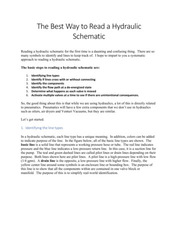
RECOMMENDED PLANETARY GEAR OILPREVAILING AMBIENT 120130 oFMOBILGEAR 600 XP 220 OR EQUIVALENTAGMA 5 EP, ISO VG 220MOBILGEAR 600 XP 150 OR EQUIVALENTAGMA 4 EP, ISO VG 150MOBILGEAR SHC 150SYNTHETIC OR EQUIVALENToC-40i-30-20-1001020304050oCNOTE: SHADED TEMPERATURE RANGE IN THE CHART ABOVE NOT RECOMMENDED FOR SEVERE APPLICATIONS SUCH AS: OFFSHORECRANES, SUSTAINED FAST DUTY CYCLES OR FREQUENT LIFTING.Planetary hoists are factory filled with Mobilgear 600 XP 150, or equivalent. Consult your oil supplier for other equivalentoils if required.ShellChevronTexacoMobilgear 600 XP 150MobilOmala 150Gear Compounds EP 150Meropa 150Mobilgear 600 XP 220Omala 220Gear Compounds EP 220Meropa 220OIL CAPACITIES:NOTE: Capacities are approximate. Refer to “OilLevel” earlier in this section(PD12C/PD15B) 01, 02 & 22 DRUM - 6 PINTS (2.8 L)(PD12C/PD15B) 04, 05 & 23G DRUM - 7 PINTS (3.3 L)(PD17A) - 14 PINTS (6.6 L)TROUBLESHOOTING! WARNING !If a hoist ever exhibits any sign of erratic operation, or load control difficulties (i.e. load creeping or chattering)appropriate troubleshooting tests and repairs should be performed immediately. Continued operation in thismanner may result in property damage, serious personal injury or death.TROUBLEPROBABLE CAUSEREMEDY1. The problem could be a pluggedor loose pilot orifice. The pilot orifice is a small pipe plug with a holedrilled through it, located behind thepilot port fitting on the brake valve.If it becomes plugged, it will preventthe pilot pressure, from the manifold, from opening the brake valve.If it becomes loose, it will allow anunregulated amount of oil in to operate the brake valve which causeerratic brake valve operation.Remove the pilot hose and fittingfrom the brake valve, then use a5/32 inch Allen wrench to removethe pilot orifice. The diameter of theorifice is approximately .020 inches.Clean and install the pilot orificetightly in the brake valve.2. The friction brake may not bereleasing as a result of a defectivebrake cylinder seal.Check brake cylinder seal as follows:AThe hoist will not lower the load ornot lower the load smoothly.NOTE: If the brake cylinder sealis defective you will usually find oilleaking from the hoist vent plug.A. Disconnect the swivel tee fromthe brake release port. Connect ahand pump with accurate 0-2000psi gauge and shut-off valve to the–4 J.I.C. fitting in the brake releaseport.12
TROUBLEPROBABLE CAUSEREMEDYAThe hoist will not lower the load ornot lower the load smoothly.1. Friction brake will not release asa result of damaged brake discs.A. Apply 1000 PSI (6,900 kPa) tothe brake. Close shut-off valve andlet stand for five (5) minutes.B. If there is any loss of pressurein five (5) minutes, the brake cylinder should be disassembled for inspection of the sealing surfaces andreplacement of the seals. Refe
The output planet carrier is splined to the bearing sup-port and cannot rotate. Therefore, as the output planet gears are driven by the sun gear, they will drive the ring gear/drum. DUAL BRAKE SYSTEM - DESCRIPTION The dual brake system consists of a dynamic brake system and a static brake sys