Transcription
Vehicle inspectorsbulletin14PUBLISHED 2 APRIL 2009 REV. 4Supersedes VIB 14 Rev. 3 April 2000Test procedures for air brake systemsPurposeTo advise Heavy Vehicle Authorised Inspection Station (HVAIS) examiners of the procedures to beused for the inspection and testing of compressed air brake systems on heavy vehicles.IntroductionThe procedures described in this bulletin are to be used for the inspection and testing of compressed airbrake systems on heavy vehicles. The procedures also apply to vehicles equipped with vacuum operatedbrakes (ie air pressure also means vacuum in this instance).Before carrying out these test procedures note the following: Some bogie-drive vehicles may be fitted with differential interlocks or power dividers which arepermanently engaged. Caution must be used when testing these axle groups on brake roller testersas drive will be transmitted to the axle which is not turning. This will cause the vehicle to climb outof the rollers unless that axle is jacked clear of the ground. Use wheel chocks where testing is not on a brake roller tester, to prevent the vehicle from movingin the event of brake release or failure. Always select suitable level ground. The vehicle should be operated by the vehicle owner (or their representative) during these tests. Observe any manufacturer’s shut-down instructions before switching off the engine (eg idle enginefor five minutes to prevent turbo charger damage). Suitable fittings may be required to exhaust air from self-sealing air line connectors.ContentsSection 1Pre-ADR 35 Heavy vehicles equipped with single or dual circuit compressed air brake systemPage 2Section 2ADR 35 or ADR 35/-- Heavy vehicles equipped with compressed air brake systemsPage 5Section 3Brake componentsFor:Cc: HVAIS Proprietors and Examiners Engineering Signatories RTA Inspectors Vehicle RegulationFor further enquiriesRTA Technical Enquiries, PO Box 1120, Parramatta NSW 2124T 1300 137 302 F 02 9843 3821 E tech-enq@rta.nsw.gov.auRTA/Pub. 09.050 Cat No. 45070741Page 9 RTA Registry Service Managerswww.rta.nsw.gov.au1 (9 pages)
Section 1. Pre-ADR 35 heavy vehiclesequipped with single or dual circuit compressed air brake systemsBRAKE SYSTEM REQUIREMENTS1. Drain valveA manual or automatic drain valve must be fitted at the lowest point of each air brake reservoir in thesystem.2. Pressure warning deviceEach vehicle must be equipped with a low air pressure (or low vacuum) warning device that providesthe driver with an audible or visible warning that the vehicle manufacturer’s minimum safe working brakeair pressure or vacuum has been reached.This device can be either a buzzer, a red warning light, a flag, or a gauge (marked to instantly show aminimum safe operating pressure).Where a single brake power unit is used (ie in some air/hydraulic or vacuum systems) an audible warningdevice must be fitted.When these devices first activate, there must remain sufficient air pressure or vacuum to provide for twofull applications of the service brake.3. Tractor protection systemEvery motor vehicle which is equipped to tow a trailer must be provided with a tractor protectionsystem designed to protect its air brake system in the event of inadvertent separation from its trailer.The tractor protection device must prevent the towing vehicle’s brake system air pressure from fallingbelow the manufacturer’s minimum requirement (if known) or 300 kPa (45 psi).This device must provide an audible or visible warning to the driver that it has activated.Note: In some vehicles, this warning device may also function as the low air pressure warning device.4. Air system charging timeThe time taken to charge the air system from empty to 80% of the governor cut-out pressure must notexceed 5 minutes.Vehicles with vacuum operated brakes must be capable of charging their systems after being fullydepleted, from buzzer ‘ON’ to buzzer ‘OFF’ in 30 seconds and from buzzer ‘ON’ to normal operatinglevel in 60 seconds.BRAKE TEST PROCEDURE1. Generally inspect all of the vehicle’s brake equipment including drums/discs, brake hoses andchambers, slack adjusters and actuators, relay valves, tanks, pipes and fittings, etc. Check that components are secured and are not deteriorated, worn or damaged. Check for over-travel of slack adjusters during brake application. Check the condition of compressor hoses/fittings, drive belt & pulley (if fitted). Check for the presence of the compressor air filter. Check for the presence of visible brake failure indicators and ensure they are operational.Vehicle inspectors bulletin No. 14 Rev. 4 2 April 20092 (9 pages)
2. Have the driver start the engine and build up sufficient air pressure so that the low air warningdevice is off. Then, have the driver apply the service brakes several times until this device activates. Note the pressure at which this occurs.3. Have the driver build the air back up until maximum air pressure is reached (ie to the governorcut-out point).The maximum pressure reached must not exceed the manufacturer’s allowable maximumoperating pressure limit (if known), or 650 kPa. Note this pressure limit as it is required later. Once this pressure has been reached, have the driver switch off the engine (the ignition mayneed to be returned to the ‘ON’ position for the gauges to operate). Observe any manufacturer’s shut down instructions before switching off the engine(eg idle engine for five minutes to prevent turbo charger damage).4. Check service brake operation. Ensure that the parking brake control is in the ‘OFF’ position. For truck/trailer combinations equipped with hand controls, ensure that the brake proportioningdevice is in the ‘FULL-ON’ position. Have the operator apply the service brake and hold the pedal depressed. Check that the brakes operate on all wheels by observing movement of ‘slack adjusters’ or in thecase of wedge brakes, by gripping the air line and feeling for a pulse in the line when the brakesare applied (take care not to damage the line during this operation). Listen for any leaks (other than the normal exhausting of valves) and watch for any drop in airpressure while the service brake is applied.A maximum drop of more than 20 kPa (plus 5 kPa for each attached trailer) is unacceptable. Ensure that the actuators release immediately the brake pedal is released.5. Have the driver release and fully apply the service brake another four times.The air pressure must not drop below half of the maximum level achieved in step 3.6. Have the driver continue to apply and release the service brake pedal to completelydrain air pressure.Spring brakes which apply at this stage must only operate after the low pressure warning deviceactuates (see step 2).Once activated, the spring brakes must be capable of being released at least twice by application ofthe spring brake release control.This spring brake release control must be located within reach of the driver when seated in thenormal driving position.7. Instead of spring brakes, some vehicles may be fitted with parking lock actuators.(see Section 3 – Brake components).These actuators must be provided with a separate source of air, protected from the service brakesystem. This air source is to provide emergency braking in the event of total air pressure loss in theservice brake system.To check this function, the emergency brake must apply and release when all service brake pressureis depleted.Ensure that this system functions while the vehicle is stationary before carrying out the emergencybrake test.Vehicle inspectors bulletin No. 14 Rev. 4 2 April 20093 (9 pages)
8. Have the driver re-start the engine and build up air to the maximum limit (see previous item 3).The engine may run at maximum speed for this test.The time to charge the system from zero to 80% of this maximum limit must not exceed fiveminutes.For vacuum operated systems, the time taken to charge the system must not exceed 30 secondsfrom buzzer ‘ON’ to buzzer ‘OFF’ and must not exceed 60 seconds from buzzer ‘OFF’ to thenormal operating limit.9. Carry out a service brake performance test. Have the driver build up maximum air pressure (if necessary), then either:— Accelerate the vehicle to 35 km/h and apply the service brake – the vehicle must stop in16.5 metres, or— Accelerate the vehicle to any speed and apply the service brake – an average deceleration of2.8 m/s2 (or 29%g) must be achieved.For truck/trailer combinations the proportioning device might need to be adjusted.10. Carry out a parking brake performance test. Have the driver apply the parking brake (this might also be the emergency brake). Ensure that the parking brake operates by trying to move the vehicle under light throttle whilethe parking brakes are applied.The parking brake control must remain in the ‘ON’ position when applied. If the parking brake fails, immediately apply the service brake.11. Carry out an emergency brake performance test. Have the driver apply the emergency brake control (this might also be the parking brake control)and watch that the relevant brake chambers work. Have the driver build up maximum air pressure (if necessary), then either:— Accelerate the vehicle to 35 km/h and apply the emergency brake – the vehicle must stop in40.5 metres, or— Accelerate the vehicle to any speed and apply the emergency brake – an average deceleration of 1.1 m/s2 (or 12%g) must be achieved.If the emergency brake fails, immediately apply the service brake.12. For a truck/trailer combination, ensure that the tractor protection valve is in the normaloperating position and that the vehicle is at full air pressure. Disconnect the trailer air lines and allow air to exhaust (suitable fittings may be required). Ensure that the truck’s service brakes will still operate. Check that the trailer breakaway system has actuated by attempting to move the truck/trailercombination under light throttle.The air brakes on any trailer or semi-trailer must not apply together with the spring brakes byoperation of the one control.If any spring brakes are fitted to the prime mover they must not operate until after the low airwarning device has activated (ie 300 kPa) and the tractor protection device operates.Vehicle inspectors bulletin No. 14 Rev. 4 2 April 20094 (9 pages)
Section 2. ADR 35 or ADR 35/00 heavy vehiclesequipped with compressed air brake systemsBRAKE SYSTEM REQUIREMENTS1. Drain valveA manual or automatic drain valve must be fitted at the lowest point of each air brake reservoir in thesystem.2. Air pressure gaugesEach vehicle must be equipped with air pressure gauges that show air pressure in each sub-circuit of thebrake system.Dual circuit vehicles with a single gauge (having a separate needle for each sub-circuit) satisfy thisrequirement.Single circuit vehicles are only required to have one gauge.3. Pressure warning deviceEach vehicle must be equipped with a low air pressure (or low vacuum) warning device which providesthe driver with a visible warning that the vehicle manufacturer’s minimum safe working brake air pressureor vacuum has been reached.This device can be either a red warning light, a flag or a gauge (marked to instantly show a minimum safeoperating pressure).This device should operate before the pressure drops below 400 kPa (60 psi) in either sub-circuit.Where a single brake power unit is used (ie in some air/hydraulic or vacuum systems), an audiblewarning device must also be fitted.When these devices first activate, there must remain sufficient air pressure or vacuum to provide for twofull applications of the service brake.4. Braking systemThese vehicles must be equipped with a service brake (or primary) system, a secondary brake systemand a park brake system.The service brake provides the main braking force for the vehicle and may have either a single circuit ora dual (split) circuit system.The secondary brake system provides supplementary vehicle braking in the event of a failure in theservice brake system.The park brake is designed only to retain the vehicle in a stationary position and not to provide anydeceleration forces.5. Tractor protection systemEvery motor vehicle which is equipped to tow a trailer must be provided with a tractor protectionsystem designed to protect its air brake system in the event of inadvertent separation from its trailer.The tractor protection device must prevent the towing vehicle’s brake system air pressure from fallingbelow 300 kPa (45 psi) or the manufacturer’s minimum if known.This device must provide an audible or visible warning to the driver that it has activated.Vehicle inspectors bulletin No. 14 Rev. 4 2 April 20095 (9 pages)
6. Air system charging timeThe time taken to charge the air system from empty to 80% of the governor cut out pressure must notexceed 5 minutes.Vehicles with vacuum operated brakes must be capable of charging their systems after being fullydepleted, from buzzer ‘ON’ to buzzer ‘OFF’ in 30 seconds and from buzzer ‘ON’ to normal operatinglevel in 60 seconds.BRAKE TEST PROCEDURE1. Generally inspect all of the vehicle’s brake equipment including drums/discs, brake hoses &chambers, slack adjusters & actuators, relay valves, tanks, pipes & fittings etc. Check that components are secured and are not deteriorated, worn or damaged. Check for over-travel of slack adjusters during brake application. Check the condition of compressor hoses/fittings, drive belt & pulley (if fitted). Check for the presence of the compressor air filter. Check for the presence of visible brake failure indicators and ensure they are operational. Identify the service brake system, the secondary brake system & the park brake system. Thisinformation will be useful later in this procedure.2. Have the driver start the engine and build up sufficient air pressure so that the low air warningdevice is off. Then, have the driver apply the service brakes several times until this device activates. Note the pressure at which this occurs.3. Have the driver build the air back up until maximum air pressure is reached (ie to the governorcut-out point).This must not exceed the manufacturer’s maximum operating pressure limit (if known), or 1120 kPa(160 psi). Note this pressure limit as it is required later. Once this pressure has been reached, have the driver switch off the engine (the ignition mayneed to be returned to the ‘ON’ position for the gauges to operate). Observe any manufacturer’s shut-down instructions before switching off the engine (eg idleengine for five minutes to prevent turbo charger damage).4. Check service brake operation. Ensure that the parking brake control is in the ‘OFF’ position. For truck/trailer combinations equipped with hand controls, ensure that the brake proportioningdevice is in the full ‘ON’ position. Have the operator apply the service brake and hold the pedal depressed. Check that the brakes operate on all wheels and that the actuators release immediately thebrake pedal is released. Listen for any leaks (other than the normal exhausting of valves) and watch for any drop in airpressure while the service brake is applied. A maximum drop of more than 20 kPa (plus 5 kPa for each attached trailer) is unacceptable.Vehicle inspectors bulletin No. 14 Rev. 4 2 April 20096 (9 pages)
5. Have the driver release and fully apply the service brake pedal another four times.The air pressure in either of the sub-circuits must not fall below half of the maximum systempressure (see step 3).6. Then, have the driver continue to deplete the air by applying the service brake pedal until zeropressure is obtained in both sub-circuits.Spring brakes which apply at this stage must only operate after the low pressure warning deviceactuates (see step 2).The spring brake release control must be located within reach of the driver when seated in thenormal driving position.7. Have the driver re-start the engine and build up air to the maximum limit (see step 3).The engine may run at maximum speed for this test.The time to charge the system from zero to 80% of this maximum limit must not exceed fiveminutes.For a vacuum operated system, the time taken to charge the system must not exceed 30 secondsfrom buzzer ‘ON’ to buzzer ‘OFF’ and must not exceed 60 seconds from buzzer ‘OFF’ back to thenormal operating limit.8. Have the driver stop the engine (see previous note) and ensure all brakes have been released. Drain one sub-circuit of the service brake system.The presence of oil or fuel in brake reservoirs indicates a faulty or damaged compressor and is areason for rejection. Watch the air pressure gauge(s) to ensure that pressure in only one sub-circuit is draining. Theother sub-circuit must not drain. Once the circuit is fully drained close the drain valve. The spring brakes should not apply duringthis operation. However, please note:— That ADR 35/-- and ECE R13 both require brake tests to be conducted with the enginerunning.— For certain vehicles spring brakes may apply if the engine is not running and the service brakecircuit has been fully depleted of air.— In a single circuit service brake system, energy to hold the spring brakes off is supplied by aseparate dedicated reservoir.— In a dual circuit service brake system, spring brakes are normally held off by residual linepressure. Repeated applications of the service brake will cause the spring brakes to apply,which is acceptable. Regardless of whether the spring brakes apply have the driver depress and hold the servicebrake pedal. Examine the service brake chambers and components connected to the chargedcircuit to see that they continue to operate correctly by:— Observing movement of slack adjustors, or— Feeling for expansion in the air line (take care not to damage the line during this operation),or— Feeling the brake chamber to detect the application of the service brake through themovement of internal components (take care to avoid components that may move), or— Detecting if pressurised air exits the pressure test connection valve, which is located at eitherthe inlet to or in the body of the brake chamber. Remove the protective cover and depressthe top of the pressure test connection valve, air will be released when the service brakesare applied. Note the pressure test connection valve is only mandatory for vehiclesmanufactured after 1 July 1998. Ensure the drain valve is closed and have the driver re-start the engine and build up air to themaximum pressure. If the spring brakes have applied, determine if the spring brakes release.Vehicle inspectors bulletin No. 14 Rev. 4 2 April 20097 (9 pages)
9. For dual circuit service brake systems, repeat Step 8 for the other sub-circuit.10. Carry out a service brake performance test. Have the driver build up maximum air pressure (if necessary), then either:— Accelerate the vehicle to 35 km/h and apply the service brake - the vehicle must stop in16.5 metres, or— Accelerate the vehicle to any speed and apply the service brake - an average deceleration of2.8m/s2 (or 29%g) must be achieved.For a truck/trailer combination the proportioning device might need to be adjusted.11. Carry out a parking brake performance test. Have the driver apply the parking brake. Ensure that the parking brake operates by checking that the vehicle is prevented from movingunder light throttle while the parking brakes are applied.The parking brake control must remain in the ‘ON’ position when applied.12. For a truck/trailer combination, ensure that the tractor protection valve is in the normaloperating position and that the vehicle is at full air pressure. Disconnect the trailer air lines and allow air to exhaust (suitable fittings may be required). Check that the trailer break-away system has actuated by attempting to move the vehicle underlight throttle.If any spring brakes are fitted to the prime mover they must not operate until after the low airwarning device has activated (ie 300 kPa) and the tractor protection device operates.Vehicle inspectors bulletin No. 14 Rev. 4 2 April 20098 (9 pages)
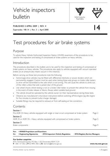
Section 3. Brake componentsFigures 1 – 3 show the internal mechanisms of some typical brake components.FIGURE 1: TYPICAL POWER BRAKE CHAMBERFIGURE 2: TYPICAL SPRING BRAKE CHAMBERFIGURE 3: TYPICAL PARK-LOCK SAFETY ACTUATORVehicle inspectors bulletin No. 14 Rev. 4 2 April 20099 (9 pages)
4. Check service brake operation. Ensure that the parking brake control is in the 'OFF' position. For truck/trailer combinations equipped with hand controls, ensure that the brake proportioning device is in the 'FULL-ON' position. Have the operator apply the service brake and hold the pedal depressed.