Transcription
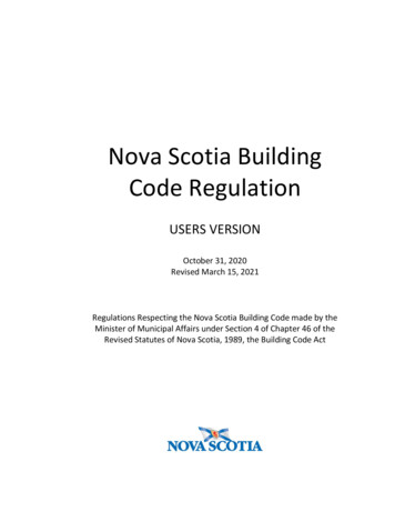
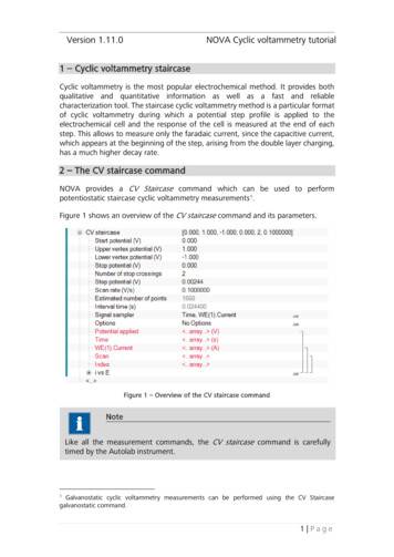
Version 1.11.0NOVA Cyclic voltammetry tutorial1 – Cyclic voltammetry staircaseCyclic voltammetry is the most popular electrochemical method. It provides bothqualitative and quantitative information as well as a fast and reliablecharacterization tool. The staircase cyclic voltammetry method is a particular formatof cyclic voltammetry during which a potential step profile is applied to theelectrochemical cell and the response of the cell is measured at the end of eachstep. This allows to measure only the faradaic current, since the capacitive current,which appears at the beginning of the step, arising from the double layer charging,has a much higher decay rate.2 – The CV staircase commandNOVA provides a CV Staircase command which can be used to performpotentiostatic staircase cyclic voltammetry measurements 1.Figure 1 shows an overview of the CV staircase command and its parameters.Figure 1 – Overview of the CV staircase commandNoteLike all the measurement commands, the CV staircase command is carefullytimed by the Autolab instrument.Galvanostatic cyclic voltammetry measurements can be performed using the CV Staircasegalvanostatic command.11 Page
NOVA Cyclic voltammetry tutorialThe CV staircase command has the following parameters: Start potential (V): defines the start potential, in Volts. The start potentialvalue can be located outside of the scan range defined by the lower andupper vertices.Upper vertex potential (V): defines the upper vertex potential, in Volts. Theupper vertex potential must be higher than the lower vertex potential.Lower vertex potential (V): defines the lower vertex potential, in Volts. Thelower vertex potential must be lower than the upper vertex potential.Stop potential: defines the stop potential, in Volts. The stop potential valuemust be located within the scan range defined by the upper and lowervertices.Number of stop crossings: defines the number that the scan should crossthe stop potential value in order to stop the measurement.Step potential (V): defines the length of the potential step used in the CVstaircase command, in Volts. The step potential can be positive or negative.With a positive step, the scan starts from the start potential towards theupper vertex potential. With a negative step, the scan direction is reversed.Scan rate (V/s): defines the scan rate, in Volts per second 2.Signal sampler: defines the specific sampler used during the CV staircase.By default, Time, Potential applied and WE(1).Current are measured, butadditional electrochemical signals can be added to the sampler. Moreover,the Scan signal, which provides the scan number, will be added to the data.Options: defines the options used during the cyclic voltammetrymeasurement (automatic current ranging and cutoffs). WarningImportant restrictions: in order to properly identify the scans in the data, it isimportant to make sure that the following conditions are respected whendefining the parameters of the CV staircase command: The Stop potential must be than the Upper vertex potential – thepotential step.The Stop potential must be than the Lower vertex potential thepotential step.If these conditions are not respected, NOVA will try to adjust the parameters to theclosest possible solution, but in this case the correct identification of the scannumbers cannot be guaranteed.The CV staircase command in NOVA provides a flexible framework for the definitionof the scan parameters. In a typical cyclic voltammetry experiment, it is assumedBecause of the maximum sampling rate of the ADC164 module, the scan rate (in V/s) divided bythe potential step (in V) should always be lower than 12.000 s-1, with only one signal defined in thesampler.22 Page
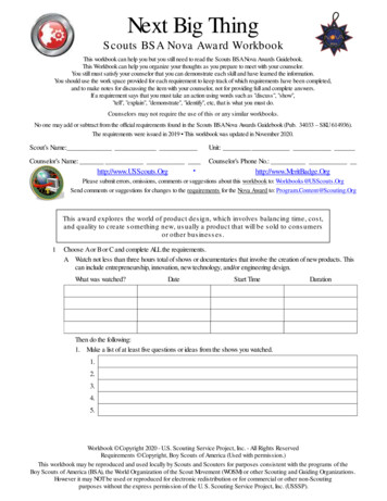
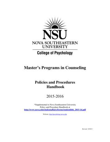
NOVA Cyclic voltammetry tutorialthat the start and stop potentials should be the same. With NOVA, this is not thecase anymore, and the user is free to define any type a potential scan using the setof parameters available.2.1 – Comparison with the Cyclic voltammetry staircase of GPESThere are two very significant differences between the Nova Cyclic voltammetrystaircase and the GPES version.1. Nova CV staircase has four different potentials: Start, Upper vertex, Lowervertex and Stop potential. The CV in GPES does not have a Stop potential.2. Nova CV staircase does not have a number of cycles but a number of stopcrossings.These two differences allow for more flexibility when building a potential profilefor cyclic voltammetry. The example shown in Figure 2 has the followingparameters. Start potential: 1.2 V, upper vertex: 1 V, lower vertex: -0.5 V, stoppotential: 0.8 V, number of stop crossings: 5.Figure 2 – Example of cyclic voltammetry in NOVA3 Page
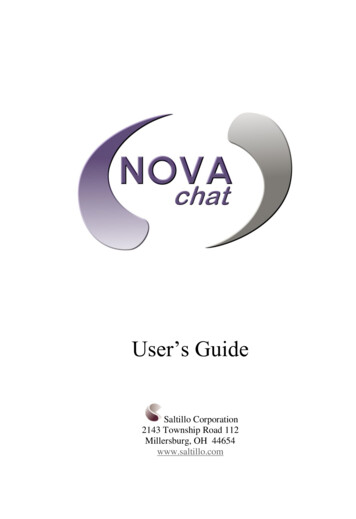
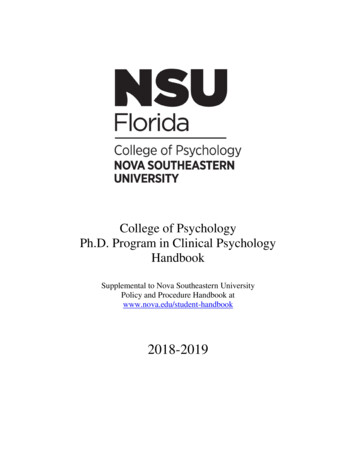
NOVA Cyclic voltammetry tutorial3 – Using the CV staircase commandThe standard Autolab Cyclic voltammetry potentiostatic procedure provides a goodexample of the CV staircase command (see Figure 3).Figure 3 – The Autolab Cyclic voltammetry potentiostatic procedureThe Autolab Cyclic voltammetry procedure performs a single scan, from 0 V to anupper vertex potential of 1 V, then to a lower vertex potential of -1 V and finallystopping at a potential of 0 V. The number of stop crossings is 2.Figure 4 shows the potential profile of this experiment.4 Page
NOVA Cyclic voltammetry tutorialFigure 4 – The potential profile applied with the two stop crossings used in the Autolab cyclicvoltammetry potentiostatic procedureIn the Autolab cyclic voltammetry potentiostatic procedure, the stop potential isequal to the start potential.4 – Changing the scan directionIn the CV staircase command, the scan direction is defined by the sign of the steppotential. If the step potential is positive, the scan direction will be from the startpotential to the upper vertex potential (see Figure 4). If the step potential is negative,the scan direction will be from the start potential to the lower vertex potential.If the Autolab cyclic voltammetry potentiostatic procedure is repeated, using a steppotential of -0.00244 V instead of 0.00244 V, the potential profile will be identicalto the one displayed in Figure 5.5 Page
NOVA Cyclic voltammetry tutorialFigure 5 – The potential profile applied with the two stop crossings used in the Autolab cyclicvoltammetry potentiostatic procedure, with a negative potential stepNoteIt is possible to change the scan direction during a cyclic voltammogram usingthebutton, available in the Autolab display (see Figure 6).6 Page
NOVA Cyclic voltammetry tutorialFigure 6 – Pressing thebutton changes the scan direction during a measurementThebutton can be pressed any number of times to reverse the scandirection. The measurement stops when the number of stop crossings has beenreached.5 – Changing the number of scansThe number of scans in the CV staircase command is defined by the number of stopcrossings. This unusual definition of the number of scans has many advantages thatwill be illustrated in this tutorial.Two stop crossings are required for one cycle. This means that it is possible to usean odd value as the number of stop crossings, in order to perform an extra half scanat the end of the measurement.Figure 7 shows the potential profile obtained with the Autolab cyclic voltammetryprocedure, using three stop crossings instead of two. The first two stop crossingsdefine the first cycle and the third stop crossing defines the second, half cycle.7 Page
NOVA Cyclic voltammetry tutorialFigure 7 – The potential profile applied with three stop crossings6 – Using different start and stop potentialsUnlike other implementations of the cyclic voltammetry method, it is possible, withthe CV staircase command in NOVA to use a different start and stop potential.In the standard Autolab Cyclic voltammetry potentiostatic procedure, the start andstop potentials are linked and are therefore identical. If the link is removed, it ispossible to define different values of the start and the stop potential.Figure 8 shows an example of a potential profile used during the CV staircasecommand corresponding to a start potential of 0 V, a stop potential of 0.2 V and anumber of stop crossings equal to 3.8 Page
NOVA Cyclic voltammetry tutorialFigure 8 – Using different start and stop potentials in the CV staircase commandThe measurement starts at 0 V and stops at 0.2 V. The number of stop crossings isthree. A number of stop crossings equal to 2 would have generated less than half ascan.7 – Start potential outside of the scan rangeA final benefit of the CV staircase command is the possibility of defining a startpotential outside of the scan range. Figure 9 shows an example of such a potentialprofile. In this example, the start potential is -2 V whereas the stop potential is 0 V.Again, three stop crossings are required for the first scan to be complete.NoteThe stop potential value must be unlinked from the start potential. Please referto the User Manual for more information (see Section 2.4.4).9 Page
NOVA Cyclic voltammetry tutorialFigure 9 – The CV staircase command allows the start potential can be located outside of thescan rangeNoteThe stop potential value must always be located within the scan range definedby the upper and lower vertex potential.8 – Circular buffersNOVA uses so-called circular buffers in the CV staircase command. These buffershave a defined length, but can be cycled through an infinite amount of time, unlikelinear buffers. This means that when the number of scans is high, the number ofdata points recorded can exceed the length of the circular buffer. This means thatonly the last X measured data points will be saved at the end of the experiment,where X is the length of the circular buffer.NOVA will display a warning during validation when the estimated number of pointsexceeds the length of the circular buffer (see Figure 10).10 P a g e
NOVA Cyclic voltammetry tutorialFigure 10 – A warning is displayed during validation when the circular buffer is exceededNoteThe length of the circular buffer is optimized when the procedure is started inorder to maximize the memory use on the embedded processor of the Autolab.11 P a g e
1 - Cyclic voltammetry staircase Cyclic voltammetry is the most popular electrochemical method. It provides both qualitative and quantitative information as well as a fast and reliable characterization tool. The staircase cyclic voltammetry method is a particular format of cyclic voltammetry during which a step profile is appotential plied to the

![Nova-Life Full Crack [Keygen] - Heroku](/img/60/novalife-full-crack-keygen.jpg)