Transcription
Citrix NetScaler Clustering GuideCitrix NetScaler 10
Copyright and Trademark Notice CITRIX SYSTEMS, INC., 2012. ALL RIGHTS RESERVED. NO PART OF THIS DOCUMENT MAY BEREPRODUCED OR TRANSMITTED IN ANY FORM OR BY ANY MEANS OR USED TO MAKE DERIVATIVE WORK(SUCH AS TRANSLATION, TRANSFORMATION, OR ADAPTATION) WITHOUT THE EXPRESS WRITTENPERMISSION OF CITRIX SYSTEMS, INC.ALTHOUGH THE MATERIAL PRESENTED IN THIS DOCUMENT IS BELIEVED TO BE ACCURATE, IT ISPRESENTED WITHOUT WARRANTY OF ANY KIND, EXPRESS OR IMPLIED. USERS MUST TAKE ALLRESPONSIBILITY FOR THE USE OR APPLICATION OF THE PRODUCT(S) DESCRIBED IN THIS MANUAL.CITRIX SYSTEMS, INC. OR ITS SUPPLIERS DO NOT ASSUME ANY LIABILITY THAT MAY OCCUR DUE TO THEUSE OR APPLICATION OF THE PRODUCT(S) DESCRIBED IN THIS DOCUMENT. INFORMATION IN THISDOCUMENT IS SUBJECT TO CHANGE WITHOUT NOTICE. COMPANIES, NAMES, AND DATA USED INEXAMPLES ARE FICTITIOUS UNLESS OTHERWISE NOTED.The following information is for FCC compliance of Class A devices: This equipment has been tested and found tocomply with the limits for a Class A digital device, pursuant to part 15 of the FCC rules. These limits are designed toprovide reasonable protection against harmful interference when the equipment is operated in a commercialenvironment. This equipment generates, uses, and can radiate radio-frequency energy and, if not installed and used inaccordance with the instruction manual, may cause harmful interference to radio communications. Operation of thisequipment in a residential area is likely to cause harmful interference, in which case users will be required to correct theinterference at their own expense.Modifying the equipment without Citrix' written authorization may result in the equipment no longer complying with FCCrequirements for Class A digital devices. In that event, your right to use the equipment may be limited by FCCregulations, and you may be required to correct any interference to radio or television communications at your ownexpense.You can determine whether your equipment is causing interference by turning it off. If the interference stops, it wasprobably caused by the NetScaler appliance. If the NetScaler equipment causes interference, try to correct theinterference by using one or more of the following measures:Move the NetScaler equipment to one side or the other of your equipment.Move the NetScaler equipment farther away from your equipment.Plug the NetScaler equipment into an outlet on a different circuit from your equipment. (Make sure the NetScalerequipment and your equipment are on circuits controlled by different circuit breakers or fuses.)Modifications to this product not authorized by Citrix Systems, Inc., could void the FCC approval and negate yourauthority to operate the product.BroadCom is a registered trademark of BroadCom Corporation. Fast Ramp, NetScaler, and NetScaler Request Switchare trademarks of Citrix Systems, Inc. Linux is a registered trademark of Linus Torvalds. Internet Explorer, Microsoft,PowerPoint, Windows and Windows product names such as Windows NT are trademarks or registered trademarks ofthe Microsoft Corporation. NetScape is a registered trademark of Netscape Communications Corporation. Red Hat is atrademark of Red Hat, Inc. Sun and Sun Microsystems are registered trademarks of Sun Microsystems, Inc. Otherbrand and product names may be registered trademarks or trademarks of their respective holders.Portions of this software may be redistributed under an open source license. Information about those portions of thesoftware, including a listing of all third party attribution notices and open source license agreements can be found at http://www.citrix.com/lang/English/lp/lp 2305124.asp.All rights reserved.Last Updated: July 2012Document code: July 19 2012 02:03:50
ContentsClustering.7NetScaler Features Supported by a Cluster. . . . . . . . . . . . . . . . . . . . . . . . . . . . . . . . . . . . . . . . . . . . . . . . . .7Hardware and Software Requirements. . . . . . . . . . . . . . . . . . . . . . . . . . . . . . . . . . . . . . . . . . . . . . . . . . . . . . .9How Clustering Works. . . . . . . . . . . . . . . . . . . . . . . . . . . . . . . . . . . . . . . . . . . . . . . . . . . . . . . . . . . . . . . . . . . . . . . . .9Cluster Synchronization. . . . . . . . . . . . . . . . . . . . . . . . . . . . . . . . . . . . . . . . . . . . . . . . . . . . . . . . . . . . . . . . .10Cluster Connections. . . . . . . . . . . . . . . . . . . . . . . . . . . . . . . . . . . . . . . . . . . . . . . . . . . . . . . . . . . . . . . . . . . . .11Striped and Spotted IP Addresses. . . . . . . . . . . . . . . . . . . . . . . . . . . . . . . . . . . . . . . . . . . . . . . . . . . . . .12Traffic Distribution. . . . . . . . . . . . . . . . . . . . . . . . . . . . . . . . . . . . . . . . . . . . . . . . . . . . . . . . . . . . . . . . . . . . . . .13Cluster and Node States. . . . . . . . . . . . . . . . . . . . . . . . . . . . . . . . . . . . . . . . . . . . . . . . . . . . . . . . . . . . . . . .15Setting up a NetScaler Cluster. . . . . . . . . . . . . . . . . . . . . . . . . . . . . . . . . . . . . . . . . . . . . . . . . . . . . . . . . . . . . . .15Setting up the Cluster Backplane. . . . . . . . . . . . . . . . . . . . . . . . . . . . . . . . . . . . . . . . . . . . . . . . . . . . . . .16Creating a NetScaler Cluster. . . . . . . . . . . . . . . . . . . . . . . . . . . . . . . . . . . . . . . . . . . . . . . . . . . . . . . . . . .17To create a cluster by using the NetScaler command line. . . . . . . . . . . . . . . . . . . . . . . .17To create a cluster by using the configuration utility. . . . . . . . . . . . . . . . . . . . . . . . . . . . . .18Adding a Node to the Cluster. . . . . . . . . . . . . . . . . . . . . . . . . . . . . . . . . . . . . . . . . . . . . . . . . . . . . . . . . . .19To add a node to the cluster by using the NetScaler command line. . . . . . . . . . . . .20To add a node to the cluster by using the configuration utility. . . . . . . . . . . . . . . . . . . .21To join a previously added node to the cluster by using the configuration utility. . . . . . . . . . . . . . . . . . . . . . . . . . . . . . . . . . . . . . . . . . . . . . . . . . . . . . . . . . . . . . . . . . . . . . . . . . . . . . . . . . . . . .21Removing a Cluster Node. . . . . . . . . . . . . . . . . . . . . . . . . . . . . . . . . . . . . . . . . . . . . . . . . . . . . . . . . . . . . . 22To remove a cluster node by using the NetScaler command line. . . . . . . . . . . . . . . .22To remove a cluster node by using the configuration utility. . . . . . . . . . . . . . . . . . . . . . .23Viewing the Details of a Cluster. . . . . . . . . . . . . . . . . . . . . . . . . . . . . . . . . . . . . . . . . . . . . . . . . . . . . . . . 23To view details of a cluster instance by using the NetScaler command line. . . . .23To view details of a cluster node by using the NetScaler command line. . . . . . . . .23To view details of a cluster instance by using the configuration utility. . . . . . . . . . . .24To view details of a cluster node by using the configuration utility. . . . . . . . . . . . . . .24Distributing Traffic Across Cluster Nodes. . . . . . . . . . . . . . . . . . . . . . . . . . . . . . . . . . . . . . . . . . . . . . . . . . . .24Using Equal Cost Multiple Path (ECMP). . . . . . . . . . . . . . . . . . . . . . . . . . . . . . . . . . . . . . . . . . . . . . .24To configure ECMP on the NetScaler cluster by using the NetScaler commandline. . . . . . . . . . . . . . . . . . . . . . . . . . . . . . . . . . . . . . . . . . . . . . . . . . . . . . . . . . . . . . . . . . . . . . . . . . . . . . . . . .25Using Cluster Link Aggregation Group (CLAG). . . . . . . . . . . . . . . . . . . . . . . . . . . . . . . . . . . . . . . .27iii
ContentsStatic Cluster Link Aggregation Group. . . . . . . . . . . . . . . . . . . . . . . . . . . . . . . . . . . . . . . . . . . .28Dynamic Cluster Link Aggregation Group. . . . . . . . . . . . . . . . . . . . . . . . . . . . . . . . . . . . . . . . .30Using Linksets. . . . . . . . . . . . . . . . . . . . . . . . . . . . . . . . . . . . . . . . . . . . . . . . . . . . . . . . . . . . . . . . . . . . . . . . . . .30To configure a linkset by using the NetScaler command line. . . . . . . . . . . . . . . . . . . . .32To configure a linkset by using the configuration utility. . . . . . . . . . . . . . . . . . . . . . . . . . .33Managing the NetScaler Cluster. . . . . . . . . . . . . . . . . . . . . . . . . . . . . . . . . . . . . . . . . . . . . . . . . . . . . . . . . . . . .33Disabling a Cluster Node. . . . . . . . . . . . . . . . . . . . . . . . . . . . . . . . . . . . . . . . . . . . . . . . . . . . . . . . . . . . . . .33To disable a cluster node by using the NetScaler command line. . . . . . . . . . . . . . . .33To disable a cluster node by using the configuration utility. . . . . . . . . . . . . . . . . . . . . . .34Discovering NetScaler Appliances. . . . . . . . . . . . . . . . . . . . . . . . . . . . . . . . . . . . . . . . . . . . . . . . . . . . . .34Viewing the Statistics of a Cluster. . . . . . . . . . . . . . . . . . . . . . . . . . . . . . . . . . . . . . . . . . . . . . . . . . . . . .35To view the statistics of a cluster instance by using the NetScaler commandline. . . . . . . . . . . . . . . . . . . . . . . . . . . . . . . . . . . . . . . . . . . . . . . . . . . . . . . . . . . . . . . . . . . . . . . . . . . . . . . . . .35To view the statistics of a cluster node by using the NetScaler command line. . . . . . . . . . . . . . . . . . . . . . . . . . . . . . . . . . . . . . . . . . . . . . . . . . . . . . . . . . . . . . . . . . . . . . . . . . . . . . . . . . . . . .35To view the statistics of a cluster instance by using the configuration utility. . . . .36To view the statistics of a cluster node by using the configuration utility. . . . . . . . .36Synchronizing Cluster Configurations. . . . . . . . . . . . . . . . . . . . . . . . . . . . . . . . . . . . . . . . . . . . . . . . . .36To synchronize cluster configurations by using the NetScaler command line. . . . . . . . . . . . . . . . . . . . . . . . . . . . . . . . . . . . . . . . . . . . . . . . . . . . . . . . . . . . . . . . . . . . . . . . . . . . . . . . . . . . . .37To synchronize cluster configurations by using the configuration utility. . . . . . . . . .37Synchronizing Cluster Files. . . . . . . . . . . . . . . . . . . . . . . . . . . . . . . . . . . . . . . . . . . . . . . . . . . . . . . . . . . . .37To synchronize cluster files by using the NetScaler command line. . . . . . . . . . . . . .38To synchronize cluster files by using the configuration utility. . . . . . . . . . . . . . . . . . . . .38Synchronizing Time on Cluster Nodes. . . . . . . . . . . . . . . . . . . . . . . . . . . . . . . . . . . . . . . . . . . . . . . . .39To enable/disable PTP by using the NetScaler command line. . . . . . . . . . . . . . . . . . .39To enable/disable PTP by using the configuration utility. . . . . . . . . . . . . . . . . . . . . . . . . .39Upgrading or Downgrading Software of the Cluster. . . . . . . . . . . . . . . . . . . . . . . . . . . . . . . . . . .39To upgrade or downgrade the software of the cluster nodes. . . . . . . . . . . . . . . . . . . . .40Use Cases. . . . . . . . . . . . . . . . . . . . . . . . . . . . . . . . . . . . . . . . . . . . . . . . . . . . . . . . . . . . . . . . . . . . . . . . . . . . . . . . . . . .40Creating a Two-Node Cluster. . . . . . . . . . . . . . . . . . . . . . . . . . . . . . . . . . . . . . . . . . . . . . . . . . . . . . . . . . .40Migrating an HA Setup to a Cluster Setup. . . . . . . . . . . . . . . . . . . . . . . . . . . . . . . . . . . . . . . . . . . . .41To convert a HA setup to cluster setup by using the NetScaler command line. . . . . . . . . . . . . . . . . . . . . . . . . . . . . . . . . . . . . . . . . . . . . . . . . . . . . . . . . . . . . . . . . . . . . . . . . . . . . . . . . . . . . .41Using Cache Redirection in a Cluster. . . . . . . . . . . . . . . . . . . . . . . . . . . . . . . . . . . . . . . . . . . . . . . . . .42Using CLAG with Linksets. . . . . . . . . . . . . . . . . . . . . . . . . . . . . . . . . . . . . . . . . . . . . . . . . . . . . . . . . . . . . .42To use CLAG and linksets by using the NetScaler command line. . . . . . . . . . . . . . .43Backplane on LA Channel. . . . . . . . . . . . . . . . . . . . . . . . . . . . . . . . . . . . . . . . . . . . . . . . . . . . . . . . . . . . . .43iv
Citrix NetScaler Clustering GuideCommon Interfaces for Client and Server and Dedicated Interfaces for Backplane. . . . . . . . . . . . . . . . . . . . . . . . . . . . . . . . . . . . . . . . . . . . . . . . . . . . . . . . . . . . . . . . . . . . . . . . . . . . . . . . . . . . . . . . . . .44Common Switch for Client, Server, and Backplane. . . . . . . . . . . . . . . . . . . . . . . . . . . . . . . . . . . .46Common Switch for Client and Server and Dedicated Switch for Backplane. . . . . . . . .48Multiple Switches for Each Node. . . . . . . . . . . . . . . . . . . . . . . . . . . . . . . . . . . . . . . . . . . . . . . . . . . . . . . 51Different Switch for Every Node. . . . . . . . . . . . . . . . . . . . . . . . . . . . . . . . . . . . . . . . . . . . . . . . . . . . . . . . 52Sample Cluster Configurations. . . . . . . . . . . . . . . . . . . . . . . . . . . . . . . . . . . . . . . . . . . . . . . . . . . . . . . . . 53Troubleshooting the NetScaler Cluster. . . . . . . . . . . . . . . . . . . . . . . . . . . . . . . . . . . . . . . . . . . . . . . . . . . . . . 55Tracing the Packets of a NetScaler Cluster. . . . . . . . . . . . . . . . . . . . . . . . . . . . . . . . . . . . . . . . . . . . 56To trace packets of a standalone appliance. . . . . . . . . . . . . . . . . . . . . . . . . . . . . . . . . . . . . . .56To trace packets of a cluster. . . . . . . . . . . . . . . . . . . . . . . . . . . . . . . . . . . . . . . . . . . . . . . . . . . . . . .56Merge multiple trace files. . . . . . . . . . . . . . . . . . . . . . . . . . . . . . . . . . . . . . . . . . . . . . . . . . . . . . . . . . 57Examples. . . . . . . . . . . . . . . . . . . . . . . . . . . . . . . . . . . . . . . . . . . . . . . . . . . . . . . . . . . . . . . . . . . . . . . . . . .57Troubleshooting Common Issues. . . . . . . . . . . . . . . . . . . . . . . . . . . . . . . . . . . . . . . . . . . . . . . . . . . . . . .58FAQs. . . . . . . . . . . . . . . . . . . . . . . . . . . . . . . . . . . . . . . . . . . . . . . . . . . . . . . . . . . . . . . . . . . . . . . . . . . . . . . . . . . . . . . . . .60Operations Supported on Individual Nodes. . . . . . . . . . . . . . . . . . . . . . . . . . . . . . . . . . . . . . . . . . . . . . . . . 63A Documentation Library. . . . . . . . . . . . . . . . . . . . . . . . . . . . . . . . . . . . . . . . . . . . . . . . . . . . . . . . . . . . . . . . . . . . . . . . . . . . . .65Release Notes. . . . . . . . . . . . . . . . . . . . . . . . . . . . . . . . . . . . . . . . . . . . . . . . . . . . . . . . . . . . . . . . . . . . . . . . . . . . . . . .66Quick Start Guides. . . . . . . . . . . . . . . . . . . . . . . . . . . . . . . . . . . . . . . . . . . . . . . . . . . . . . . . . . . . . . . . . . . . . . . . . . . 66Configuration Guides. . . . . . . . . . . . . . . . . . . . . . . . . . . . . . . . . . . . . . . . . . . . . . . . . . . . . . . . . . . . . . . . . . . . . . . . .67Reference Guides. . . . . . . . . . . . . . . . . . . . . . . . . . . . . . . . . . . . . . . . . . . . . . . . . . . . . . . . . . . . . . . . . . . . . . . . . . . . 67v
Contentsvi
ClusteringA NetScaler cluster is a group of NetScaler nCore appliances working together as asingle system image. Each appliance of the cluster is called a node. A NetScaler clustercan include as few as 2 or as many as 32 NetScaler nCore hardware or virtualappliances as nodes.The client traffic is distributed between the nodes to provide high availability, highthroughput, and scalability.To create a cluster, you add the required NetScaler appliances as cluster nodes, set upcommunication between the nodes, set up links to the client and server networks,configure the NetScaler appliances, and configure the distribution of client and servertraffic.NetScaler Features Supported by a ClusterThe following table lists the NetScaler features that are fully supported on the cluster,features that only work on individual cluster nodes, and features that are notsupported on the cluster.Table 1-1. NetScaler feature support matrixSupported featuresFeatures supported atnode-levelUnsupported featuresw Load Balancingw Surge Protectionw DNS Load Balancingw Load BalancingPersistencyw Sure Connectw FTP Load Balancingw Priority Queuingw Global Server LoadBalancing (GSLB)w SIPw maxClientw HTTP Denial-of-ServiceProtection (HTTP DoSP)w Spilloverw Integrated Cachingw RTSPw SSL PI policyw Call Homew Stateful ConnectionFailoverw Content Switchingw Cache Redirectionw Compression Controlw Content Filteringw OSPF (IPv4 and IPv6)w RIP (IPv4 and IPv6)w BGP (IPv4 and IPv6)w NetScaler Pushw Graceful Shutdownw DBS Auto Scalingw DSR using TOSw Spillover based onbandwidthw Finer Startup-RRControl7
ClusteringSupported featuresUnsupported featuresw HTML Injectionw Rate Limitingw TCP Bufferingw Stream Analyticsw Distributed Denial-ofService (DDoS)w Net Profilew DNS Cachingw Basic Networking (IPv4and IPv6)w SSL-VPNw VLANw SSL CPE policyw ICMPw Application Firewallw Fragmentationw AAAw MAC-Based Forwarding(MBF)w Cloud Bridging Tunnelingw RNATw Layer2 Modew INATw FIPSw KRPCw XML XSMw ACLw AAA-TMw Simple ACLw VMAC/VRRPw PBRw Link Load Balancingw SNMP GET/SET, Walkw IP-IP Tunnelingw SNMP Trapsw DHCP RAw Policy Infrastructure(PE/PI)w Bridge Groupw NITRO APIw AppExpertw Web Interface onNetScalerw Rewritew EdgeSight Monitoringw Responderw BR LBw Use Source IP (USIP)w ISIS Routingw AppFlow exporter andAppflow collector(client) with waterfallchartw FIS (Failover InterfaceSet)w DataStreamw MSR8Features supported atnode-levelw Network Bridge
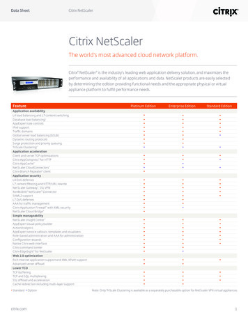
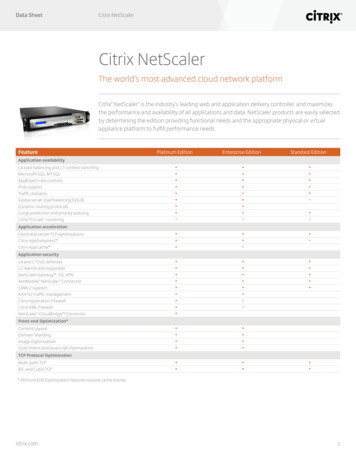
Citrix NetScaler Clustering GuideSupported featuresFeatures supported atnode-levelUnsupported featuresw Policy-based RNATw Web loggingw Auditing (syslog andnsauditlog)w Path MTU Discoveryw Client Keep-aliveHardware and Software RequirementsAppliances that you add to a NetScaler cluster must satisfy the following requirements:w Be NetScaler nCore appliances. Clustering of NetScaler Classic appliances is notsupported.w Be of the same platform type (physical appliance or VPX instance).w Be of the same hardware type (for physical appliances).w Be on the same subnet.w Have the cluster license file.w Have the same licenses (Standard, Enterprise, or Platinum, and any add-on licenses).w Be of the same software version and build.w Be initially configured and connected to a common client-side and server-sidenetwork.How Clustering WorksA NetScaler cluster is formed by grouping NetScaler appliances that satisfyrequirements specified in Hardware and Software Requirements on page 9. One of thecluster nodes is designated as a configuration coordinator (CCO). As the name suggests,the CCO coordinates all cluster configurations through the management IP address ofthe cluster, which is called the cluster IP address.The cluster must be configured by accessing the CCO through the cluster IP address, asshown in the following figure:9
ClusteringFigure 1-1. Configuring the cluster through the cluster IP addressNote: You cannot configure an individual node by accessing it through the NetScalerIP (NSIP) address. Nodes accessed through the NSIP address are available in readonly mode. This means that you can only view the configurations and the statistics.However, there are some commands that can be executed on individual nodes. Formore information, see Operations Supported on Individual Nodes on page 63.The VIP addresses that you define on a cluster are available on all the nodes of thecluster (striped addresses). You can define SNIP addresses to be available on all nodes(striped addresses) or only on a single node (spotted addresses). The details of trafficdistribution in a cluster depend on the algorithm used, but the same logical entitiesprocess the traffic in each case.Cluster SynchronizationWhen a node is added to the cluster, the NetScaler configurations and the files (SSLcertificates, licenses, DNS, and so on) that are available on the CCO are synchronizedon the newly added cluster node. This ensures that the configurations and files arealways synchronized on all the nodes of the cluster.When an existing cluster node rejoins the cluster (after it failed or was intentionallydisabled), the cluster checks the configurations available on the node. If there is amismatch in the configurations available on the rejoined node and on the CCO, thenode is synchronized by using one of the following techniques:w Full synchronization. If the difference between configurations exceeds 255commands, all of the configurations implemented on the CCO are applied to thenode that is rejoining the cluster. The node remains operationally unavailable forthe duration of the synchronization.w Incremental Synchronization. If the difference between configurations is less thanor equal to 255 commands, only the configurations that are not available areapplied to the node that is rejoining the cluster. The operational state of the noderemains unaffected.The configurations that are performed on the CCO through the cluster IP address, areautomatically propagated to the cluster nodes. Since, the cluster configurations arebased on a quorum of the available nodes, a command (that is executed on the cluster10
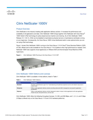
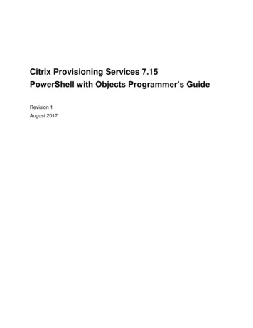
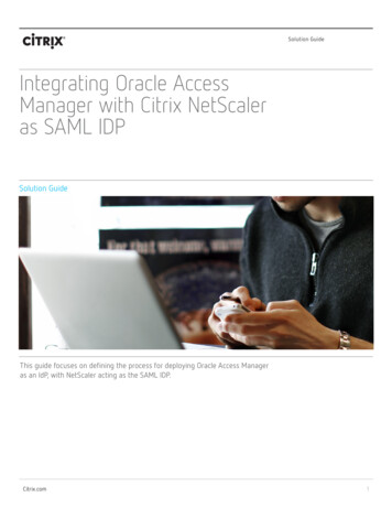
Citrix NetScaler Clustering GuideIP address) can be propagated to the other cluster nodes only when a majority of thenodes are in synch. If a majority of the nodes are not in synch or are in the process ofsynchronizing, they cannot accept new commands and therefore commands are notpropagated till the synchronization is complete.Cluster ConnectionsTo identify the node to which an interface belongs, the standard NetScaler interfacenaming convention is prefixed with a node ID. That is, the interface identifier c/u,where c is the controller number and u is the unit number, becomes n/c/u, where n isthe node ID.For example, in the following figure, interface 1/2 of Node 0 is represented as 0/1/2,interface 1/1 of Node 1 is represented as 1/1/1, and interface 1/4 of Node 2 isrepresented as 2/1/4.Figure 1-2. Network interfaces naming convention in a clusterThe cluster communicates with the client through the physical connections betweenthe cluster node and the client-side connecting device. The logical grouping of thesephysical connections is called the client data plane. Similarly, the clustercommunicates with the server through the physical connections between the clusternodes and the server-side connecting device. The logical grouping of these physicalconnections is called the server data plane.In addition to communicating with the client and server through the client data planeand server data plane, respectively, the cluster nodes communicate with each other byusing the cluster backplane. The backplane, which includes the physical connectionsfrom each cluster node and the backplane switch, is the backbone of the cluster system.11
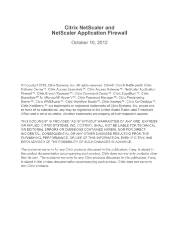
ClusteringFigure 1-3. Cluster communication interfacesThe above figure shows the logical grouping of the physical connections to form theclient data plane, server data plane, and cluster backplane.Striped and Spotted IP AddressesIn a clustered deployment, VIP and SNIP addresses, can be striped or spotted.w A striped IP address is active on all the nodes of the cluster. IP addresses configuredon the cluster without specifying an owner node are active on all the cluster nodes.w A spotted IP address is active on and owned exclusively by one node. IP addressesconfigured on the cluster by specifying an owner node are active only on the nodethat is specified as the owner.The following figure shows striped and spotted IP addresses in a three-node cluster.12
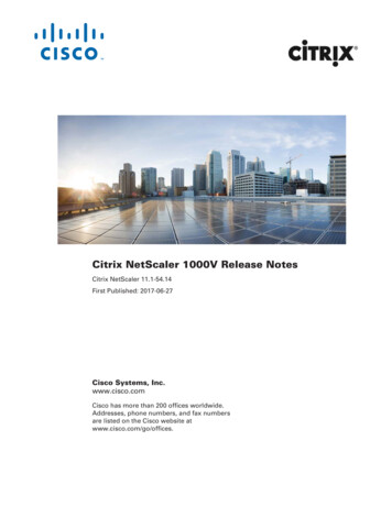
Citrix NetScaler Clustering GuideFigure 1-4. Three-node cluster with striped and spotted IP addressesIn the above figure, the VIP address 10.102.29.66 is striped on all the cluster nodes,and SNIP address 10.102.29.99 is striped on NS0 and NS1. NS2 has a spotted SNIP address.The following table shows the NetScaler-owned IP addresses that can be striped orspotted:Table 1-2. Striped and Spotted IP addressesNetScaler-owned IP addressesStriped IP addressesSpotted IP addressesNSIPNoYesCluster IP addressNoNoVIPYesNoSNIPYesYes (recommended)Note:w The cluster IP address is not a striped or spotted IP address. It is a floating IPaddress that is owned by the CCO, which is not a fixed node.w Citrix recommends that you use only spotted IP addresses. You can use striped IPaddresses only if there is a shortage of IP addresses. The use of striped IPaddresses can result in ARP flux issues.Traffic DistributionThe NetScaler cluster uses Equal Cost Multiple Path (ECMP) or Cluster Link AggregationGroup (CLAG) traffic distribution mechanisms to determine the node that receives thetraffic (the flow receiver) from the external connecting device. Each of thesemechanisms uses a different algorithm to determine the flow receiver. The flowreceiver then uses internal cluster logic to determine the node that process the traffic(the flow processor).Note: The flow receiver and flow processor must be nodes capable of serving traffic.13
ClusteringFigure 1-5. Traffic distribution in a clusterThe above figure shows a client request flowing through the cluster. The client sends arequest to a striped virtual IP (VIP) address. A traffic distribution mechanismconfigured on the client data plane selects one of the cluster nodes as the flowreceiver. The flow receiver receives the traffic, determines the node that must processthe traffic, and steers the request to that node through the cluster backplane (unlessthe flow receiver selects itself as the flow processor).The flow processor establishes a connection with the server. The server processes therequest and sends the response to the subnet IP (SNIP) address that sent the request tothe server.w If the SNIP address is a striped IP address, the traffic distribution mechanismconfigured on the server data plane selects one of the cluster nodes (that owns theSNIP address) as the flow receiver. The flow receiver receives the traffic,determines the flow processor, and steers the request to the flow processor throughthe cluster backplane.14
Citrix NetScaler Clustering Guidew If the SNIP address is a spotted IP address, the node that owns the SNIP addressreceives the response from the server.In an asymmetric cluster topology (all cluster nodes are not connected to the externalswitch), you must use linksets either exclusively or combined with ECMP or CLAG. Formore information, see Using Linksets on page 30.Cluster and Node StatesCluster-node classification includes three types of states: admin state, operationalstate, and health.Admin State. An admin state is configured when you add the node to the cluster. Itindicates the purpose of the node, which can be in one of the following states:w ACTIVE. Nodes in this state serve traffic if they are operational and healthy.w PASSIVE. Nodes in this state do not serve traffic but are in sync with the cluster.These nodes are useful during maintenance activity, because they can be upgradedwithout removing the node from the cluster.w SPARE. Nodes in this state do not serve traffic but are in sync with the cluster.Spare nodes act as backup nodes for the cluster. If one of the ACTIVE nodes becomesunavailable, the operational state of one of the spare nodes becomes ACTIVE, andthat node starts serving traffic.Operational State. When a node is part of a cluster, its operational state can change toACTIVE, INACTIVE, or UNKNOWN. There are a number of reasons for a node being inINACTIVE or UNKNOWN state. Review the ns.log file or error counters to helpdetermine the exact reason.Health State. Depending on its health, a node can either be UP or NOT UP. To view thereasons for a node being in NOT UP state, run the show cluster node command for thatnode from the cluster IP address.Only nodes that have the admin state as ACTIVE, operational state as ACTIVE, andhealth status as UP can serve traffic. A cluster is functional only when a minimum of (n/2 1) nodes, where n is the number of cluster nodes, are able to serve traffic.Setting up a NetScaler ClusterTo setup a NetScaler cluster, begin by setting up the cluster backplane. Then, youcreate the cluster by adding the first node to the cluster, which becomes the initialconfiguration coordinator (CCO), and by assigning a cluster IP address to that node.Once the cluster IP address is defined on the CCO, you can add more nodes to the cluster.Every appliance that you want to add to the cluster must:w Be NetScaler nCore appliances. Clustering of NetScaler Classic appliances is notsupported.w Be of the same platform type (physical appliance or VPX instance).15
Clusteringw Be of the same hardware type (for physical appliances).w Be on the same subnet.w Have the cluster license file.w Have the same licenses (Standard, Enterprise, or Platinum, and any add-on licenses).w Be of the same software version and build.w Be initially configured and connected to a common client-side and server-sidenetwork.Only appliances that satisfy all the above criteria can be part of a NetScaler cluster.Setting up the Cluster BackplaneThe nodes in a cluster communicate with each other through the cluster backplane.The backplane is a set of connections in which one interface of each node is connectedto a common switch, which is called the cluster backplane switch. Each node of thecluster uses
A NetScaler cluster is a group of NetScaler nCore appliances working together as a single system image. Each appliance of the cluster is called a node. A NetScaler cluster can include as few as 2 or as many as 32 NetScaler nCore hardware or virtual appliances as nodes. The client traffic is distributed between the nodes to provide high .