Transcription
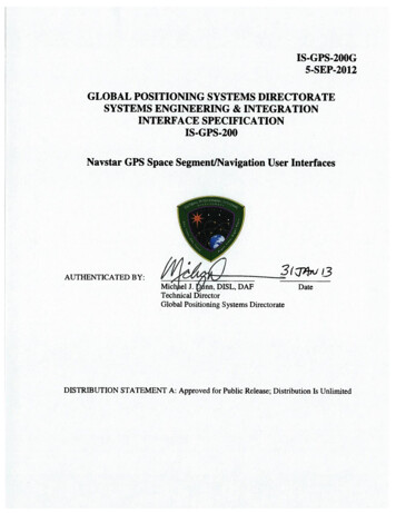
REVISION RECORDREVNCDESCRIPTIONDOCUMENTDATEAPPROVEDInitial Release25 Jan 1983AIncorporates IRN-200NC-001, IRN-200NC-002, andIRN-200NC-00325 Sep 1984BIncorporates IRN-200A-001A30 Nov 1987CIncorporates IRN-200B-001 thru IRN-200B-00710 Oct 1993CRe-formatted in Microsoft Word 6.0 in GEMScompatible format10 Oct 199312 Jan 1996CChanged distribution status to Public Release25 Sep 199720 Oct 1997Incorporates IRN-200C-001 thru IRN-200C-005R1,change ICD-GPS-200 to IS-GPS-200, introduce andspecify the requirements of Improved Clock andEphemeris (ICE) message for L2 C signal, and otheradditional updates7 Dec 200423 Nov 2004Adds additional PRN sequences to Section 67 Mar 20069 Mar 2006GPS IIIA Incorporations8 Jun 201021 Sep 20118 June 201005 Mar 201205 Sep 201231 Jan 2013DIRN200D-001EFIncorporates(IRN-IS-200E-001 (RFC 16B - Pseudorandom Noise(PRN) ExpansionIRN-IS-200E-002 (RFC 77B - Public DocumentManagement (GPS III terminology and Space ServiceVolume (SSV) group delay))IRN-IS-200E-003 (RFC 86 - User Range Accuracy(URA) Definition)IRN-IS-200E-004 (RFC 89 - Almanac Intervals)IRN-IS-200E-005 (RFC 91A - Civil Navigation(CNAV) Durations)IRN-IS-200E-006 (RFC 93 - Technical Note 36)IRN-IS-200E-007 (RFC 97 - Pseudorange Parameters)IRN-IS-200F-001GIRN-IS-200F-002 (RFC 139B – Public Signals-inSpace UpdatesiIS-GPS-200G05 Sep 2012
TABLE OF CONTENTS123INTRODUCTION . 11.1Scope. . 11.2IS Approval and Changes. 1APPLICABLE DOCUMENTS . 12.1Government Documents. . 12.2Non-Government Documents. . 2REQUIREMENTS . 33.1Interface Definition. . 33.2Interface Identification. . 33.2.1Ranging Codes. . 33.2.2NAV Data. . 123.2.3L1/L2 Signal Structure. . 123.3Interface Criteria. . 133.3.1Composite Signal. . 133.3.2PRN Code Characteristics. 193.3.3Navigation Data. . 383.3.4GPS Time and SV Z-Count. . 394NOT APPLICABLE . 425NOT APPLICABLE . 436NOTES . 446.1Acronyms . 446.2Definitions . 476.2.1User Range Accuracy. . 476.2.2SV Block Definitions. . 48iiIS-GPS-200G05 Sep 2012
6.2.3Operational Interval Definitions. . 496.2.4GPS Week Number. . 496.2.5L5 Civil Signal. . 496.36.3.1Received Signals. . 496.3.2Extended Navigation Mode (Block II/IIA). . 516.3.3Block IIA Mode (Block IIR/IIR-M) and Extended Navigation Mode (Block II-F).526.3.4Extended Navigation Mode (GPS III). . 536.3.5Autonomous Navigation Mode. . 536.3.6Additional PRN Code Sequences. . 546.3.7Pre-Operational Use. . 626.410Supporting Material. 49Operational Protocols. . 626.4.1Lower PRN Numbers Versus Upper PRN Numbers . 626.4.2PRN Number Consistency . 636.4.3PRNs 33 and 37 . 636.4.4PRNs 33 through 63 . 636.4.5Health Code Setting of ‘11110’ . 63APPENDIX I. LETTERS OF EXCEPTION . 6410.1Scope. . 6410.2Applicable Documents. . 6410.3Letters of Exception. 6420 APPENDIX II. GPS NAVIGATION DATA STRUCTURE FOR LNAV DATA, D(t), FORPRN 1-32 . 7320.1Scope. . 7320.2Applicable Documents. . 73iiiIS-GPS-200G05 Sep 2012
20.2.1 Government Documents. . 7320.2.2 Non-Government Documents. . 7320.3Requirements. . 7420.3.1 Data Characteristics. . 7420.3.2 Message Structure. . 7420.3.3 Message Content. . 8520.3.4 Timing Relationships. . 12520.3.5 Data Frame Parity. . 13130APPENDIX III. GPS NAVIGATION DATA STRUCTURE FOR CNAV DATA, DC(t) 13430.1Scope. . 13430.2Applicable Documents. . 13430.2.1 Government Documents. . 13430.2.2 Non-Government Documents. . 13430.3Requirements. . 13430.3.1 Data Characteristics. . 13430.3.2 Message Structure. . 13530.3.3 Message Content. . 13630.3.4 Timing Relationships. . 18340 APPENDIX IV GPS NAVIGATION DATA STRUCTURE FOR LNAV DATA, D(t), FORPRN 33-63 . 18840.1Scope . 18840.2Applicable Documents . 18840.3Requirements. . 18840.3.1 Data Characteristics . 18840.3.2 Message Structure . 188ivIS-GPS-200G05 Sep 2012
40.3.3 Message Content . 20040.3.4 Timing Relationships . 20740.3.5 Data Frame Parity . 207vIS-GPS-200G05 Sep 2012
LIST OF FIGURESFigure 3-1.Generation of P-, C/A-Codes and Modulating Signals . 21Figure 3-2.X1A Shift Register Generator Configuration . 23Figure 3-3.X1B Shift Register Generator Configuration . 24Figure 3-4.X2A Shift Register Generator Configuration . 25Figure 3-5.X2B Shift Register Generator Configuration . 26Figure 3-6.P-Code Generation . 28Figure 3-7.P-Code Signal Component Timing . 29Figure 3-8.G1 Shift Register Generator Configuration . 32Figure 3-9.G2 Shift Register Generator Configuration . 33Figure 3-10:Example C/A-Code Generation . 34Figure 3-11.C/A-Code Timing Relationships . 35Figure 3-12.L2 CM-/L2 CL-Code Timing Relationships . 36Figure 3-13.L2 CM/L2 CL Shift Register Generator Configuration . 37Figure 3-14.Convolutional Encoder. 38Figure 3-15.Convolutional transmit/Decoding Timing Relationships. 39Figure 3-16.Time Line Relationship of HOW Message . 41Figure 6-1.User Received Minimum Signal Level Variations (Example, Block II/IIA/IIR) 51Figure 10.3-1. Letters of Exception. . 65Figure 10.3-2. Letters of Exception (continued) . 66Figure 10.3-3. Letters of Exception (continued) . 67Figure 10.3-4. Letters of Exception (continued). . 68Figure 10.3-5. Letters of Exception (continued) . 69Figure 10.3-6. Letters of Exception (continued). . 70Figure 10.3-7. Letters of Exception (continued). . 71viIS-GPS-200G05 Sep 2012
Figure 10.3-8. Letters of Exception (continued). . 72Figure 20-1.Data Format (sheet 1 of 11). 75Figure 20-1.Data Format (sheet 2 of 11). 76Figure 20-1.Data Format (sheet 3 of 11). 77Figure 20-1.Data Format (sheet 4 of 11). 78Figure 20-1.Data Format (sheet 5 of 11). 79Figure 20-1.Data Format (sheet 6 of 11). 80Figure 20-1.Data Format (sheet 7 of 11). 81Figure 20-1.Data Format (sheet 8 of 11). 82Figure 20-1.Data Format (sheet 9 of 11). 83Figure 20-1.Data Format (sheet 10 of 11). 84Figure 20-1.Data Format (sheet 11 of 11). 85Figure 20-2.TLM and HOW Formats . 87Figure 20-3.Sample Application of Correction Parameters . 96Figure 20-4.Ionospheric Model (Sheet 1 of 3) . 123Figure 20-4.Ionospheric Model (Sheet 2 of 3). 124Figure 20-4.Ionospheric Model (Sheet 3 of 3). 125Figure 20-5.Example Flow Chart for User Implementation of Parity Algorithm . 133Figure 30-1.Message Type 10 - Ephemeris 1 . 136Figure 30-2.Message Type 11 - Ephemeris 2 . 137Figure 30-3.Message Type 30 - Clock, IONO & Group Delay . 138Figure 30-4.Message Type 31 - Clock & Reduced Almanac . 139Figure 30-5.Message Type 32 - Clock & EOP . 140Figure 30-6.Message Type 33 - Clock & UTC . 141Figure 30-7.Message Type 34 - Clock & Differential Correction . 142viiIS-GPS-200G05 Sep 2012
Figure 30-8.Message Type 35 - Clock & GGTO . 143Figure 30-9.Message Type 36 - Clock & Text . 144Figure 30-10. Message Type 37 - Clock & Midi Almanac . 145Figure 30-11. Message Type 12 - Reduced Almanac . 146Figure 30-12. Message Type 13 - Clock Differential Correction . 147Figure 30-13. Message Type 14 - Ephemeris Differential Correction . 148Figure 30-14. Message Type 15 - Text . 149Figure 30-15. Reduced Almanac Packet Content . 170Figure 30-16. Differential Correction Data Packet . 177Figure 40-1.Data Format (sheet 1 of 11) . 189Figure 40-1.Data Format (sheet 2 of 11) . 190Figure 40-1.Data Format (sheet 3 of 11) . 191Figure 40-1.Data Format (sheet 4 of 11) . 192Figure 40-1.Data Format (sheet 5 of 11) . 193Figure 40-1.Data Format (sheet 6 of 11) . 194Figure 40-1.Data Format (sheet 7 of 11) . 195Figure 40-1.Data Format (sheet 8 of 11) . 196Figure 40-1.Data Format (sheet 9 of 11) . 197Figure 40-1.Data Format (sheet 10 of 11) . 198Figure 40-1.Data Format (sheet 11 of 11) . 199viiiIS-GPS-200G05 Sep 2012
LIST OF TABLESTable 3-Ia.Code Phase Assignments (sheet 1 of 2) . 6Table 3-Ia.Code Phase Assignments (sheet 2 of 2) . 7Table 3-Ib.Expanded Code Phase Assignments (III and subsequent blocks only) . 8Table 3-IIa. Code Phase Assignments (IIR-M, IIF, and subsequent blocks only) (sheet 1 of 2) . 9Table 3-IIa. Code Phase Assignments (IIR-M, IIF, and subsequent blocks only) (sheet 2 of 2)10Table 3-IIb. Expanded Code Phase Assignments (III and subsequent blocks only) . 11Table 3-III.Signal Configuration . 13Table 3-IV.Composite L1 Transmitted Signal Phase ** (Block II/IIA and IIR SVs Only) . 16Table 3-Va. Received Minimum RF Signal Strength for Block IIA, IIR, IIR-M, IIF and IIISatellites (20.46 MHz Bandwidth) . 17Table 3-Vb. Received Minimum RF Signal Strength for GPS III (30.69 MHz Bandwidth) . 18Table 3-Vc. Space Service Volume (SSV) Received Minimum RF Signal Strength for GPS IIIand Subsequent Satellites over the Bandwidth Specified in 3.3.1.1 – GEO Based Antennas . 18Table 3-VI.P-Code Reset Timing . 30Table 3-VII. Final Code Vector States . 31Table 6-IAdditional C/A-/P-Code Phase Assignments (sheet 1 of 5) . 56Table 6-IAdditional C/A-/P-Code Phase Assignments (sheet 2 of 5) . 57Table 6-IAdditional C/A-/P-Code Phase Assignments (sheet 3 of 5) . 58Table 6-IAdditional C/A-/P-Code Phase Assignments (sheet 4 of 5) . 59Table 6-I.Additional C/A-/P-Code Phase Assignments (sheet 5 of 5) . 60Table 6-II.Additional L2 CM-/L2 CL-Code Phase Assignments (sheet 1 of 2) . 61Table 6-II.Additional L2 CM-/L2 CL-Code Phase Assignments (sheet 2 of 2) . 62Table 20-I.Subframe 1 Parameters . 92Table 20-II. Ephemeris Data Definitions . 98Table 20-III. Ephemeris Parameters. 99ixIS-GPS-200G05 Sep 2012
Table 20-IV.Elements of Coordinate Systems (sheet 1 of 2) . 100Table 20-IV.Elements of Coordinate Systems (sheet 2 of 2) . 101Table 20-V.Data IDs and SV IDs in Subframes 4 and 5 . 106Table 20-VI.Almanac Parameters . 108Table 20-VII. NAV Data Health Indications . 110Table 20-VIII. Codes for Health of SV Signal Components . 111Table 20-IX.UTC Parameters . 114Table 20-X.Ionospheric Parameters . 115Table 20-XI.IODC Values and Data Set Lengths (Block II/IIA) . 128Table 20-XII. IODC Values and Data Set Lengths (Block IIR/IIR-M/IIF & GPS III) . 129Table 20-XIII. Reference Times. 131Table 20-XIV. Parity Encoding Equations. 132Table 30-I.Message Types 10 and 11 Parameters (1 of 2) . 155Table 30-I.Message Types 10 and 11 Parameters (2 of 2) . 156Table 30-II.Elements of Coordinate System (part 1 of 2) . 157Table 30-II.Elements of Coordinate System (part 2 of 2) . 158Table 30-III.Clock Correction and Accuracy Parameters . 160Table 30-IV.Group Delay Differential Parameters **** . 165Table 30-V.Midi Almanac Parameters . 169Table 30-VI.Reduced Almanac Parameters ***** . 170Table 30-VII. Earth Orientation Parameters . 173Table 30-VIII. Application of EOP Parameters . 174Table 30-IX.UTC Parameters . 175Table 30-X.Differential Correction Parameters . 178Table 30-XI.GPS/GNSS Time Offset Parameters . 183xIS-GPS-200G05 Sep 2012
Table 30-XII. Message Broadcast Intervals . 184Table 40-V.Data IDs and SV IDs in Subframes 4 and 5 . 203xiIS-GPS-200G05 Sep 2012
1 INTRODUCTION1.1 Scope. This Interface Specification (IS) defines the requirements related to the interfacebetween the Space Segment (SS) of the Global Positioning System (GPS) and the navigationUser Segment (US) of the GPS for radio frequency (RF) link 1 (L1) and link 2 (L2).1.2 IS Approval and Changes. The Interface Control Contractor (ICC) designated by thegovernment is responsible for the basic preparation, approval coordination, distribution,retention, and Interface Control Working Group (ICWG) coordination of the IS in accordancewith GP-03-001. The Navstar GPS Directorate (SMC/GP) is the necessary authority to makethis IS effective. SMC/GP administers approvals under the auspices of the ConfigurationControl Board (CCB), which is governed by the appropriate GPS Directorate OperatingInstruction (OI). Military organizations and contractors are represented at the CCB by theirrespective segment member. All civil organizations and public interest are represented by theDepartment of Transportation representative of the SMC/GP.A proposal to change the approved version of this IS can be submitted by any ICWGparticipating organization to the GPS Directorate and/or the ICC. The ICC is responsible for thepreparation of the change paper and change coordination, in accordance with GP-03-001. TheICC prepares the change paper as a Proposed Interface Revision Notice (PIRN) and isresponsible for coordination of PIRNs with the ICWG. The ICWG coordinated PIRN must besubmitted to the GPS Directorate CCB for review and approval.The ICWG review period for all Proposed Interface Revisions Notices (PIRNs) is 45 days afterreceipt by individual addressees. A written request to extend the review period may besubmitted to the ICC for consideration.2 APPLICABLE DOCUMENTS2.1 Government Documents. The following documents of the issue specified contribute tothe definition of the interfaces between the GPS Space Segment and the GPS navigation UserSegment, and form a part of this IS to the extent specified herein.1IS-GPS-200G05 Sep 2012
SpecificationsFederalNoneMilitaryNoneOther Government ActivityNoneStandardsFederalNoneMilitaryNoneOther PublicationsGP-03-001 (GPS Interface Control Working Group Charter)International Earth Rotation and Reference Systems Service(IERS) Technical Note 362.2 Non-Government Documents. The following documents of the issue specified contributeto the definition of the interfaces between the GPS Space Segment and the GPS Navigation UserSegment and form a part of this IS to the extent specified herein.SpecificationsNoneOther PublicationsNone2IS-GPS-200G05 Sep 2012
3 REQUIREMENTS3.1 Interface Definition. The interface between the GPS Space Segment (SS) and the GPSnavigation User Segment (US) includes two RF links, L1 and L2. Utilizing these links, the spacevehicles (SVs) of the SS shall provide continuous earth coverage signals that provide to the USthe ranging codes and the system data needed to accomplish the GPS navigation (NAV) mission.These signals shall be available to a suitably equipped user with RF visibility to an SV.3.2 Interface Identification. The carriers of L1 and L2 are typically modulated by one ormore bit trains, each of which normally is a composite generated by the modulo-2 addition of apseudo-random noise (PRN) ranging code and the downlink system data (referred to as NAVdata).3.2.1 Ranging Codes. Three PRN ranging codes are transmitted: the precision (P) codewhich is the principal navigation ranging code; the Y-code, used in place of the P-code wheneverthe anti-spoofing (A-S) mode of operation is activated; and the coarse/acquisition (C/A) codewhich is used for acquisition of the P (or Y) code (denoted as P(Y)) and as a civil ranging signal.Code-division-multiple-access techniques allow differentiating between the SVs even thoughthey may transmit at the same frequencies. The SVs will transmit intentionally "incorrect"versions of the C/A and the P(Y) codes where needed to protect the users from receiving andutilizing anomalous navigation signals. These two "incorrect" codes are termed non-standardC/A (NSC) and non-standard Y (NSY) codes.For Block IIR-M, IIF, and subsequent blocks of SVs, two additional PRN ranging codes aretransmitted. They are the L2 civil-moderate (L2 CM) code and the L2 civil-long (L2 CL) code.The SVs will transmit intentionally "incorrect" versions of the L2 CM and L2 CL codes whereneeded to protect the users from receiving and utilizing anomalous navigation signals. These"incorrect" codes are termed non-standard L2 CM (NSCM) and non-standard L2 CL (NSCL)codes. The SVs shall also be capable of initiating and terminating the broadcast of NSCMand/or NSCL code(s) independently of each other, in response to CS command.Users shall only use non-dummy satellites as defined via current broadcast almanac. See Section20.3.3.5.1.2 and/or Section 40.3.3.5.1.2 for the definition of information about dummy satellitesin the almanac.3.2.1.1 P-Code. The PRN P-code for SV ID number i, for i 1 t
i IS-GPS-200G 05 Sep 2012 REVISION RECORD REV DESCRIPTION DOCUMENT DATE APPROVED NC Initial Release 25 Jan 1983 A Incorporates IRN-200NC-001, IRN-200NC-002, and IRN-200NC-003 25 Sep 1984 B Incorporates IRN-200A-001A 30 Nov 1987 C Incorporates IRN-200B-001 thru IRN-200B-007 10 Oct 1993 C Re-formatted in Microsoft Word 6.0 in GEMS .
