Transcription
GPSMAP 7X3/9X3/12X3INSTALLATION INSTRUCTIONS Important Safety InformationWARNINGFailure to follow these warnings, cautions, and notices could result in personal injury, damage to the vessel ordevice, or poor product performance.See the Important Safety and Product Information guide in the product box for product warnings and otherimportant information.When connecting the power cable, do not remove the in-line fuse holder. To prevent the possibility of injury orproduct damage caused by fire or overheating, the appropriate fuse must be in place as indicated in the productspecifications. In addition, connecting the power cable without the appropriate fuse in place voids the productwarranty.CAUTIONTo avoid possible personal injury, always wear safety goggles, ear protection, and a dust mask when drilling,cutting, or sanding.To avoid possible personal injury or damage to the device and vessel, disconnect the vessel's power supplybefore beginning to install the device.To avoid possible personal injury or damage to the device or vessel, before applying power to the device, makesure that it has been properly grounded, following the instructions in the guide.NOTICEFor the best possible performance, the device must be installed according to these instructions.When drilling or cutting, always check what is on the opposite side of the surface to avoid damaging the vessel.Read all installation instructions before proceeding with the installation. If you experience difficulty during theinstallation, contact Garmin Product Support. TA-2021/2041February 273-008A-482A-A96F-362ADA8996BA v4
Tools Needed Drill Drill bits appropriate for the device and mounting style 2Mounting styleDrill bit sizesBail with included wood screws3 mm (1/8 in.)Flush for the corner of the cutoutGPSMAP 7x3: 6.5 mm (1/4 in.)GPSMAP 9x3: 7.4 mm (5/16 in.)GPSMAP 12x3: 13.5 mm (9/16 in.)Flush with included wood screws3.5 mm (9/64 in.)Flush with included machine screws and nut plates3.5 mm (9/64 in.)3 mm (1/8 in.)Flush with included machine screws and tapped holesM3 tap#2 Phillips screwdriverJigsaw or rotary toolFile and sandpaperMarine sealant (recommended)
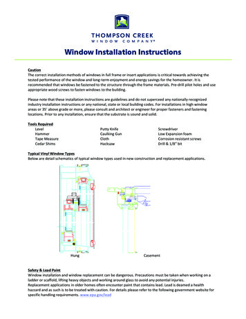
GPSMAP 7x3 and GPSMAP 9x3 Connector ViewPOWERPower and NMEA 0183 networkNETWORKGarmin Marine NetworkJ1939J1939 engine network Ground screwCVBS INComposite video inSONAR12-pin transducer (Not available on all models)USBMicro-USB for compatible Garmin card readerNMEA 2000NMEA 2000 network 2 microSD memory card slots, 32 GB max. 3
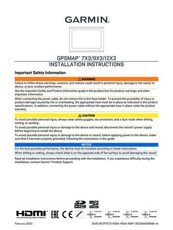
GPSMAP 12x3 Connector ViewPOWERPower and NMEA 0183 networkSONAR12-pin transducer (Not available on all models)HDMIHDMI video outCVBS INComposite video inUSBMicro-USB for compatible Garmin card reader Ground screwNETWORKGarmin Marine NetworkNMEA 2000NMEA 2000 networkJ1939Engine or J1939 network2 microSD memory card slots, 32 GB max.Contacting Garmin Support Go to support.garmin.com for help and information, such as product manuals, frequently asked questions,videos, and customer support. In the USA, call 913-397-8200 or 1-800-800-1020. In the UK, call 0808 238 0000. In Europe, call 44 (0) 870 850 1241.Software UpdateYou may need to update the chartplotter software after installation. For the instructions on how to update thesoftware, see the owner's manual at garmin.com/manuals/GPSMAP7x3-9x3-12x3.4
Mounting ConsiderationsNOTICEThis device should be mounted in a location that is not exposed to extreme temperatures or conditions. Thetemperature range for this device is listed in the product specifications. Extended exposure to temperaturesexceeding the specified temperature range, in storage or operating conditions, may cause device failure.Extreme-temperature-induced damage and related consequences are not covered by the warranty.When selecting a mounting location, you should observe these considerations. The location should provide optimal viewing as you operate your boat. The location should allow for easy access to all device interfaces, such as the keypad, touchscreen, and cardreader, if applicable. The location must be strong enough to support the weight of the device and protect it from excessivevibration or shock. To avoid interference with a magnetic compass, the device should not be installed closer to a compass thanthe compass-safe distance value listed in the product specifications. The location must allow room for the routing and connection of all cables. When flush mounting the device, the location must not be a flat, horizontal surface. The location should be ina vertical angle.The location and viewing angle should be tested before you install the device. High viewing angles fromabove and below the display may result in a poor image.5
Bail Mounting the DeviceNOTICEIf you are mounting the bracket on fiberglass with screws, it is recommended to use a countersink bit to drill aclearance counterbore through only the top gel-coat layer. This will help to avoid cracking in the gel-coat layerwhen the screws are tightened.You can use the bracket to bail mount the device on a flat surface.1 Using the bail-mount bracketas a template, mark the pilot holes234566.Using a 3 mm (1/8 in.) drill bit, drill the pilot holes.Secure the bail-mount bracket to the surface using the included washers and wood screwsInstall the bail-mount knobson the sides of the device.Place the device in the bail-mount bracket, and tighten the bail-mount knobs.Install the trim caps by snapping them in place around the edges of the device.
Flush Mounting the DeviceNOTICEBe careful when cutting the hole to flush mount the device. There is only a small amount of clearance betweenthe case and the mounting holes, and cutting the hole too large could compromise the stability of the deviceafter it is mounted.Use only the included hardware when mounting this device. Using mounting hardware not provided with thedevice may damage the device.To avoid potential damage to the powder coating, use only the included screws to mount the device. Usingscrews other than the ones included will void your warranty.Do not use the device as a template when drilling the mounting holes because this may damage the glassdisplay and void the warranty. You must only use the included template to correctly drill the mounting holes.If you will not have access to the back of the device and the microSD memory card slots after installations, youshould install the microSD memory card prior to installation.The included template and hardware can be used to flush mount the device in your dashboard. There are threeoptions for hardware based on the mounting surface material. You can drill pilot holes and use the included wood screws. You can drill holes and use the included nut plates and machine screws. The nut plates can add stability to athinner surface. You can punch and tap holes, and use the included machine screws.1 Trim the template, and make sure it fits in the location where you want to mount the device.2 Secure the template to the mounting location.3 Using a drill bit according to the list below, drill one or more of the holes inside the corners of the solid lineon the template to prepare the mounting surface for cutting.4567DeviceDrill bit sizeGPSMAP 7x36.5 mm (1/4 in.)GPSMAP 9x37.4 mm (5/16 in.)GPSMAP 12x313.5 mm (9/16 in.)Using a jigsaw or a rotary tool, cut the mounting surface along the inside line on the template.Place the device in the cutout to test the fit.If necessary, use a file and sandpaper to refine the size of the cutout.If necessary, remove the trim caps.NOTICEUse a plastic pry tool when possible. Using a metal pry tool, such as a screwdriver, can damage the trim capsand the device.8 After the device fits correctly in the cutout, ensure the mounting holes on the device line up with the holelocations on the template.NOTE: GPSMAP 12x3 models have six mounting holes. GPSMAP 9x3 and GPSMAP 7x3 models have fourmounting holes.9 If the mounting holes on the device do not line up, mark the new hole locations.10 Based on your mounting method, drill or punch and tap the outer holes on the template: For the included wood screws, drill 3.5 mm (9/64 in.) holes, and skip to step 18. For the included nut plate and machine screws, drill 3.5 mm (9/64 in.) holes in the outer hole locations. For the included machine screws without the nut plate, punch and tap M3 holes, and skip to step 18.11 If you are using a nut plate, starting in one corner of the template, place a nut plateover the holedrilled in the previous step.7
The other holeon the nut plate should line up with the inner hole on the template.12 If the inner hole on the nut plate does not line up with the inner hole on the template, mark the new holelocation.13 If you are using a nut plate, using a 3 mm (1/8 in.) drill bit, drill a hole in the inner hole location.14 Repeat to verify placement of the remaining nut plates and holes on the template.15 Remove the template from the mounting surface.16 Starting in one corner of the mounting location, place a nut platelining up the holes.The raised portion of the nut plate should fit into the inner hole.on the back of the mounting surface,17 Secure the nut plates to the mounting surface by fastening the pan head machine screwsthrough theinner holes.18 Install the foam gasketon the back of the device.The pieces of the foam gasket have adhesive on the back. Make sure you remove the protective liner beforeinstalling them on the device.19 If you will not have access to the back of the device after you mount it, connect all necessary cables andinstall microSD cards in the back of the device before placing it into the cutout.NOTICETo prevent corrosion of the metal contacts, cover unused connectors with the attached weather caps.20 Apply marine sealant between the mounting surface and the device to properly seal and prevent leakagebehind the dashboard.21 If you will have access to the back of the device, apply marine sealant around the cutout.8
22 Place the device into the cutout.23 Secure the device to the mounting surface using the flat head machine screwsor the included woodscrews.24 Wipe away all excess marine sealant.25 Install the trim capsby snapping them in place around the edges of the device.Connection ConsiderationsAfter connecting the cables to the device, tighten the locking rings to secure each cable.Power/NMEA 0183 Cable The wiring harness connects the device to power, NMEA 0183 devices, and a lamp or a horn for visible oraudible alerts. If it is necessary to extend the NMEA 0183 or alarm wires, you must use 22 AWG (.33 mm²) wire. This cable provides one differential NMEA 0183 input and output port.ItemWire ColorWire FunctionRedPowerBlackGround (power and NMEA 0183)BlueNMEA 0183 TxA (Out )GrayNMEA 0183 TxB (Out -)BrownNMEA 0183 RxA (In )VioletNMEA 0183 RxB (In -)OrangeAccessory onYellowAlarm low9
Connecting the Wiring Harness to PowerWARNINGWhen connecting the power cable, do not remove the in-line fuse holder. To prevent the possibility of injury orproduct damage caused by fire or overheating, the appropriate fuse must be in place as indicated in the productspecifications. In addition, connecting the power cable without the appropriate fuse in place voids the productwarranty.1 Route the wiring harness to the power source and to the device.2 Connect the red wire to the positive ( ) battery terminal, and connect the black wire to the negative (-) batteryterminal.3 If necessary, install the locking ring and O-ring on the end of the wiring harness.4 Insert the cable into the POWER connector on the back of the device, pushing firmly.5 Turn the locking ring clockwise to attach the cable to the device.Additional Grounding ConsiderationThis device should not need additional chassis grounding in most installation situations. If you experienceinterference, the grounding screw on the housing can be used to connect the device to the water ground of theboat to help avoid the interference.Garmin Marine Network ConsiderationsNOTICEA Garmin Marine Network PoE Isolation Coupler (010-10580-10) must be used when connecting any third-partydevice, such as a FLIR camera, to a Garmin Marine Network. Connecting a Power over Ethernet (PoE) devicedirectly to a Garmin Marine Network chartplotter damages the Garmin chartplotter and may damage the PoEdevice. Connecting any third-party device directly to a Garmin Marine Network chartplotter will cause abnormalbehavior on the Garmin devices, including the devices not properly turning off or the software becominginoperable. This device can connect to additional Garmin Marine Network devices to share data such as radar, sonar, anddetailed mapping. When connecting Garmin Marine Network devices to this device, observe theseconsiderations. All devices connected to the Garmin Marine Network must be connected to the same ground. If multiplepower sources are used for Garmin Marine Network devices, you must tie all ground connections from allpower supplies together using a low resistance connection or tie them to a common ground bus bar, ifavailable. A Garmin Marine Network cable must be used for all Garmin Marine Network connections. Third-party CAT5 cable and RJ45 connectors must not be used for Garmin Marine Network connections. Additional Garmin Marine Network cables and connectors are available from your Garmin dealer. The NETWORK ports on the device each act as a network switch. Any compatible device can be connected toany NETWORK port to share data with all devices on the boat connected by a Garmin Marine Network cable.10
NMEA 2000 ConsiderationsNOTICEIf you are connecting to an existing NMEA 2000 network, identify the NMEA 2000 power cable. Only one NMEA2000 power cable is required for the NMEA 2000 network to operate properly.A NMEA 2000 Power Isolator (010-11580-00) should be used in installations where the existing NMEA 2000network manufacturer is unknown.If you are installing a NMEA 2000 power cable, you must connect it to the boat ignition switch or throughanother in-line switch. NMEA 2000 devices will drain your battery if the NMEA 2000 power cable is connected tothe battery directly.This device can connect to a NMEA 2000 network on your boat to share data from NMEA 2000 compatibledevices such as a GPS antenna or a VHF radio. The included NMEA 2000 cables and connectors allow you toconnect the device to your existing NMEA 2000 network. If you do not have an existing NMEA 2000 network youcan create a basic one using cables from Garmin.If you are unfamiliar with NMEA 2000, you should read the Technical Reference for NMEA 2000 Products atgarmin.com/manuals/nmea 2000.The port labeled NMEA 2000 is used to connect the device to a standard NMEA 2000 network.ItemDescriptionNMEA 2000 compatible Garmin deviceGPS antennaIgnition or in-line switch11
ItemDescriptionNMEA 2000 power cableNMEA 2000 drop cable12 Vdc power sourceNMEA 2000 terminator or backbone cableNMEA 2000 T-connectorNMEA 2000 terminator or backbone cableNMEA 0183 Connection Considerations The chartplotter provides one Tx (transmit) port and one Rx (receive) port. Each port has 2 wires, labeled A and B according to the NMEA 0183 convention. The corresponding A and Bwires of each internal port should be connected to the A ( ) and B (-) wires of the NMEA 0183 device. You can connect one NMEA 0183 device to the Rx port to input data to this chartplotter, and you can connectup to three NMEA 0183 devices in parallel to the Tx port to receive data output by this chartplotter. See the NMEA 0183 device installation instructions to identify the transmit (Tx) and receive (Rx) wires. You must use 28 AWG, shielded, twisted-pair wiring for extended runs of wire. Solder all connections and sealthem with heat-shrink tubing. Do not connect the NMEA 0183 data wires from this device to power ground. The power cable from the chartplotter and the NMEA 0183 devices must be connected to a common powerground. The internal NMEA 0183 ports and communication protocols are configured on the chartplotter. See theNMEA 0183 section of the chartplotter owner's manual for more information. See the chartplotter owner's manual for a list of the approved NMEA 0183 sentences that the chartplottersupports.12
NMEA 0183 Device ConnectionsThis diagram illustrates two-way connections for both sending and receiving data. You can also use thisdiagram for one-way communication. To receive information from a NMEA 0183 device, refer to items , ,, , andwhen connecting the Garmin device. To transmit information to a NMEA 0183 device, refer toitems , , , , andwhen connecting the Garmin device.ItemDescriptionPower sourcePower/NMEA 0183 cableNMEA 0183 deviceItemGarmin Wire FunctionGarmin Wire ColorNMEA 0183 Device Wire FunctionPowerRedPowerPower groundBlackPower groundData groundBlackData groundRx/A (In )BrownTx/A (Out )Rx/B (In -)VioletTx/B (Out -)Tx/A (Out )BlueRx/A (In )Tx/B (Out -)GrayRx/B (In -)If the NMEA 0183 device has only one input (receive, Rx) wire (no A, B, , or -), you must leave the gray wireunconnected.If the NMEA 0183 device has only one output (transmit, Tx) wire (no A, B, , or -), you must connect the violetwire to ground.13
NMEA 0183 and Power Cable PinoutPin Number14Wire FunctionWire ColorNMEA 0183 Tx/A (Out )BlueNMEA 0183 Rx/A (In )BrownNMEA 0183 Tx/B (Out -)GrayNMEA 0183 Rx/B (In -)VioletAlarmYellowAccessory onOrangeGround (shield)BlackVINRed
Lamp and Horn ConnectionsThe device can be used with a lamp, a horn, or both, to sound or flash an alert when the chartplotter displays amessage. This is optional, and the alarm wire is not necessary for the device to function normally. Whenconnecting the device to a lamp or horn, observe these considerations. The alarm circuit switches to a low-voltage state when the alarm sounds. The maximum current is 100 mA, and a relay is needed to limit the current from the chartplotter to 100 mA. To manually toggle visual and audible alerts, you can install single-pole, single-throw switches.ItemDescriptionPower sourcePower cableHornLampRelay (100 mA coil current)Toggle switches to enable and disable lamp or horn alertsItemWire ColorWire FunctionRedPowerBlackGroundYellowAlarm15
J1939 Engine Network Connection ConsiderationsNOTICEYou must use a Garmin GPSMAP J1939 accessory cable when connecting the chartplotter to the J1939 enginenetwork to prevent corrosion due to moisture. Using a different cable voids your warranty.If you have an existing engine network on your boat, it should already be connected to power. Do not add anyadditional power supply.This chartplotter can connect to an engine network on your boat to read data from compatible devices such ascertain engines. The engine network follows a standard and uses proprietary messages.You should connect only one chartplotter to one engine network. Connecting more than one chartplotter to oneengine network may result in unexpected behavior.The port labeled J1939 is used to connect the device to the existing engine network. You must route the cablewithin 6 m (20 ft.) of the engine network backbone.The Garmin GPSMAP J1939 accessory cable requires connection to a power source and proper termination. Formore information on connecting to your engine network, see the manufacturer's engine documentation.PinWire ColorDescriptionBareShieldRedPower, positiveBlackPower, negativeWhiteCAN HighBlueCAN LowComposite Video ConsiderationsThis chartplotter allows video input from composite video sources using the port labeled CVBS IN. Whenconnecting composite video, you should observe these considerations. The CVBS IN port uses a BNC connector. You can use a BNC to RCA adapter to connect a composite-videosource with RCA connectors to the CVBS IN port. Video is shared across the Garmin Marine Network, but it is not shared across the NMEA 2000 network.16
HDMI Out Video ConsiderationsNOTICETo prevent corrosion due to moisture, you must use Garmin GPSMAP accessory cables when connecting thechartplotter to the video display. Using different cables voids your warranty.The GPSMAP 12x3 chartplotter models have HDMI out capability to duplicate the chartplotter screen on anotherdevice, such as a television or monitor.The Garmin GPSMAP HDMI accessory cable is 4.5 m (15 ft.) long. If you need a longer cable, you should use anactive HDMI cable only. You need an HDMI coupler to connect the two HDMI cables.You must make all cable connections in a dry environment.ItemDescriptionGPSMAP 12x3 chartplotterGPSMAP HDMI cable (HDMI)Display with an HDMI In port, such as a computer or televisionDry environment, protected from moistureInstalling the Ferrite Beads on the CablesTo comply with regulations and to reduce noise, you can install the included ferrite beads on the specifiedcables.GPSMAP 12x3Power cable and transducer cableGPSMAP 7x3/9x3Power cable, transducer cable, and USB cableSecurely snap one ferrite bead around each of the specified cables, as close to the connectors as possible.17
SpecificationsAll ModelsTemperature rangeFrom -15 to 55 C (from 5 to 131 F)MaterialPolycarbonate plastic and die-cast aluminumWater ratingIEC 60529 IPX7 1Input voltageFrom 10 to 32 VdcFuse6 A, 125 V fast-actingNMEA 2000 LEN @ 9 Vdc2NMEA 2000 draw75 mA max.USB connectorMicro-USB for compatible Garmin card reader2Wireless frequency2.4 GHz @ 18.3 dBm maximumMemory card2 microSD card slots; 32 GB max. card sizeGPSMAP 7x3Dimensions (W H D)192.3 140.3 74.1 mm (7 9/16 5 1/2 2 15/16 in.)Dimensions with cover on bail mount (W H D)200.2 156.3 101.2 mm ( 77/8 61/8 4 in.)Clearance to next obstruction behind chartplotter27.8 mm (2 in.)Display size (W H)154.6 91.0 mm (6 1/16 3 9/16 in.)17.8 cm (7.0 in.) diagonalDisplay resolutionWSVGA, 1024 600 pixelsWeight1.3 kg (2.8 lb.)Compass-safe distance35 cm (13.78 in.)Max. power usage at 10 VdcNon-sonar models: 17.6 WSonar models: 35.9 WTypical current draw at 12 VdcNon-sonar models: 1.08 ASonar models: 1.18 AMax. current draw at 12 VdcNon-sonar models: 1.45 ASonar models: 2.96 AGPSMAP 9x3Dimensions (W H D)233.0 162.3 75.8 mm (9 3/16 6 3/8 3 in.)Dimensions with cover on bail mount (W H D)256.2 178.1 104.7 mm (101/16 x 7 x 41/8 in.)Clearance to next obstruction behind chartplotter33.2 mm (15/8 in.)Display size (W H)198.7 111.8 mm (7 13/16 4 3/8 in.)22.9 cm (9.0 in.) diagonalDisplay resolutionWXGA, 1280 720 pixels1 Thedevice withstands incidental exposure to water of up to 1 m for up to 30 min. For more information, go to www.garmin.com/waterrating.compatible Garmin card readers recommended. Third-party card readers are not guaranteed to be fully compatible.2 Only18
Weight1.6 kg (3.6 lb.)Compass-safe distance30 cm (11.81 in.)Max. power usage at 10 VdcNon-sonar models: 22.0 WSonar models: 40.2 WTypical current draw at 12 VdcNon-sonar models: 1.34 ASonar models: 1.37 AMax. current draw at 12 VdcNon-sonar models: 1.78 ASonar models: 3.20 AGPSMAP 12x3Dimensions (W H D)308.3 227.6 81.8 mm (12 1/8 8 15/16 3 1/4 in.)Dimensions with cover on bail mount (W H D)327.2 246.3 113.8 mm (127/8 911/16 41/2 in.)Clearance to next obstruction behind chartplotter18.7 mm (3/4 in.)Display size (W H)262.1 164.2 mm (10 15/16 6 7/16 in.)30.7 cm (12.1 in.) diagonalDisplay resolutionWXGA, 1280 800 pixelsWeight3.0 kg (6.6 lb.)Compass-safe distance45 cm (17.72 in.)Max. power usage at 10 VdcNon-sonar models: 26.5 WSonar models: 43.0 WTypical current draw at 12 VdcNon-sonar models: 1.67 ASonar models: 1.68 AMax. current draw at 12 VdcNon-sonar models: 2.15 ASonar models: 3.56 A19
NMEA 2000 PGN InformationTransmit and ReceivePGNDescription059392ISO acknowledgment059904ISO request060160ISO transport protocol: Data transfer060416ISO transport protocol: Connection management060928ISO address claimed065240Commanded address126208Request group function126996Product information126998Configuration information127237Heading/track control127245Rudder127250Vessel heading127258Magnetic variance127488Engine parameters: Rapid update127489Engine parameters: Dynamic127493Transmission parameters: Dynamic127505Fluid level127508Battery status128259Speed: Water referenced128267Water depth129025Position: Rapid update129026COG and SOG: Rapid update129029GNSS position data129283Cross track error129284Navigation data129539GNSS DOPs129540GNSS satellites in view130060Label130306Wind data130310Environmental parameters (obsolete)130311Environmental parameters (obsolete)20
PGNDescription130312Temperature (obsolete)TransmitPGNDescription126464Transmit and receive PGN list group function126984Alert Response127497Trip parameters: EngineReceivePGNDescription065030Generator average basic AC quantities (GAAC)126983Alert126985Alert text126987Alert threshold126988Alert value126992System time127251Rate of turn127252Heave127257Attitude127498Engine parameters: Static127503AC input status (obsolete)127504AC output status (obsolete)127506DC detailed status127507Charger status127509Inverter status128000Nautical leeway angle128275Distance log129038AIS class A position report129039AIS class B position report129040AIS class B extended position report129044Datum129285Navigation: Route, waypoint information129794AIS class A static and voyage related data129798AIS SAR aircraft position report21
PGNDescription129799Radio frequency/mode/power129802AIS safety-related broadcast message129808DSC call Information129809AIS class B "CS" static data report, part A129810AIS class B "CS" static data report, part B130313Humidity130314Actual pressure130316Temperature: Extended range130576Trim tab status130577Direction data22
NMEA 0183 InformationTransmitSentenceDescriptionGPAPBAPB: Heading or track controller (autopilot) sentence "B"GPBODBOD: Bearing (origin to destination)GPBWCBWC: Bearing and distance to waypointGPGGAGGA: Global positioning system fix dataGPGLLGLL: Geographic position (latitude and longitude)GPGSAGSA: GNSS DOP and active satellitesGPGSVGSV: GNSS satellites in viewGPRMBRMB: Recommended minimum navigation informationGPRMCRMC: Recommended minimum specific GNSS dataGPRTERTE: RoutesGPVTGVTG: Course over ground and ground speedGPWPLWPL: Waypoint locationGPXTEXTE: Cross track errorPGRMEE: Estimated errorPGRMMM: Map datumPGRMZZ: AltitudeSDDBTDBT: Depth below transducerSDDPTDPT: DepthSDMTWMTW: Water temperatureSDVHWVHW: Water speed and headingReceiveSentenceDescriptionDPTDepthDBTDepth below transducerMTWWater temperatureVHWWater speed and headingWPLWaypoint locationDSCDigital selective calling informationDSEExpanded digital selective callingHDGHeading, deviation, and variation23
SentenceDescriptionHDMHeading, magneticMWDWind direction and speedMDAMeteorological compositeMWVWind speed and angleVDMAIS VHF data-link messageYou can purchase complete information about National Marine Electronics Association (NMEA) format andsentences from www.nmea.org.24
J1939 InformationThe chartplotter can receive J1939 sentences. The chartplotter cannot transmit over the J1939 network.DescriptionPGNSPNEngine percent load at current speed6144392Engine speed61444190Engine manifold exhaust gas temperature - right manifold650312433Engine manifold exhaust gas temperature - left manifold650312434Engine auxiliary coolant65172Active diagnostic trouble codes65226Vehicle distance65248Water in fuel indicator65279Engine wait to start lamp652521081Engine over speed test652522812Engine air shutoff command status652522813Engine alarm output command status652522814Engine total hours of operation65253247Navigation-based vehicle speed65256517Engine fuel temperature 165262174Engine oil temperature 165262175Engine fuel delivery pressure6526394Engine oil pressure65263100Engine coolant pressure65263109Engine coolant temperature65263110Engine coolant level65263111Engine fuel rate65266183Engine average fuel economy65266185Engine intake manifold #1 pressure65270102Battery potential / power input 165271168Transmission oil temperature65272177Transmission oil pressure65272127Fuel level6527696Engine oil filter differential pressure6527696925
��电路板组件屏幕/背光金属零件电缆 电缆组件 连接器本表格依据 SJ/T11364 的规定编制。: �该种有害物质均低于(GB/T26572) 规定的限量: 代表此种部件所用的均质材料中, �(GB/T26572) 规定的限量* 设备合规一 ) 工作于 2.4 GHz 频段的 ANT 技术无线遥控设备 , 使用频率 : 2.4 GHz, 发射功率限值 : 10 mW (e.i.r.p.)(e.i.r.p),频率容限 : 170 kHz二) 自更改发射天线;三) ��护;四) �医疗( ISM �台(站)干扰;五) ��施消除干扰后方可继续使用;六) �)、机场等的电磁环境保护 ��七) � 5000 � 微功率设备使用时温度 -15–55 和电压 10–32 Vdc 2 �性電機設備之干擾。26
�路 68 號電話:(02)2642-8999客服專線:(02)2642-9199 2020 Garmin Ltd. or its subsidiariesGarmin , the Garmin logo, and GPSMAP are trademarks of Garmin Ltd. or its subsidiaries, registered in the USA and other countries. These trademarks may not be usedwithout the express permission of Garmin. NMEA , NMEA 2000 , and the NMEA 2000 logo are registered trademarks of the National Marine Electronics Association. HDMI is a registered trademark of HDMILicensing, LLC. The SDHC logo is a trademark of SD-3C, LLC. Wi‑Fi is a registered trademark of Wi-Fi Alliance Corporation. GPSMAP 1223/1243/1253/1223xsv/1243xsv/1253xsv, GPSMAP 723/743/753/723xsv/743xsv/753xsv, GPSMAP 923/943/953/923xsv/943xsv/953xsvnM/N: A0387, B03873, A03875FCC: IPH-03873, IPH-03875 IC: 1792A-03873,
Tools Needed Drill Drill bits appropriate for the device and mounting style Mounting style Drill bit sizes Bail with included wood screws 3 mm (1/8 in.) Flush for the corner of the cutout