Transcription
MDS Master StationTechnical ManualModular Communications PlatformFirmware Version 4.1.6 and higher.Technical ManualDECEMBER 2016Technical ManualMDS 05-6399A01, Rev. F
Quick-Start instructions for this product are contained in publication 05-6398A01.Visit our website for downloadable copies of all documentation at www.gemds.com.IMPORTANTThis manual describes the details, installation, configuration and operation of theMDS Master Station. It does not cover the description or configuration of features andsettings common to the MDS Orbit family of products. For full information onconfiguring the parts of the system that are not directly related to SD/LN networking orthe MDS Master Station, please reference the MDS Orbit MCR Technical Manual(p/n: 05-6632A01). The MDS Master Station manual is designed to be used inparallel with the MCR Technical Manual, and as such does NOT cover informationalready described in that manual.
TABLE OF CONTENTS1.0INTRODUCTION . 91.1 Organization of Manual. 9Related Publications . 102.0KEY PRODUCT FEATURES. 112.12.22.32.4Accessories and Spare Items . 13FCC Emission Designators: How to Find Them . 15Front Panel. 15Rear Antenna Connections . 163.0INSTALLATION PLANNING . 173.1 Applications . 17Repeater and Polling Remote Operation (MPRS Only) . 18Simplex and Switched Carrier Operation . 183.2 Network Management. 18MPRS Network-Wide Diagnostics . 18MPRS Network Management Using PulseNET . 183.3 Redundant versus Non-redundant Operation . 193.4 Antennas and Feedlines . 19Antennas. 19Feedlines . 193.5 Grounding Considerations . 203.6 Data Interface Connections . 21Ethernet Data Interface (RJ-45) . 21Serial Data Interfaces . 21MPRS Serial Data Connection . 21Mini USB . 22Alarm Output and 4-Wire Audio . 224.0INSTALLATION PROCEDURES . 234.1 Unpacking and Inspection . 234.2 Installation Steps. 23Initial Startup & Operation . 26Module LED Indicators . 26Normal Indications . 27Maximizing RSSI . 275.0DEVICE MANAGEMENT . 285.1 Pre-Configured Settings . 285.2 One-Time “Recovery” Passwords . 28One-Time Passwords: How They Work . 28Creating a One-Time Password . 29Logging in With a One-Time Password . 29Deleting a One-Time Password . 295.3 Configuration via Command Line (CLI) . 30Tab Completion Feature . 30MDS 05-6399A01, Rev. FMDS Master Station1
CLI Quick Reference Table . 305.4 Interface Naming. 325.5 Configuration via the Device Manager . 32General Configuration . 335.6 Interface Configuration . 34Understanding . 34Configuring . 345.7 LAN. 38Understanding . 38Configuring . 385.8 Bridging . 40Understanding . 40Configuring . 415.9 SDMS Interface . 41Understanding . 41Configuration . 43General Settings . 44Dlink . 48MAC Settings . 49IP Payload . 51Advanced Configuration . 57Audio . 60Actions . 61Remote SD Reprogramming . 65Monitoring . 69Performance . 705.10 SD-x/0/0 Interfaces . 71General . 71Statistics. 715.11 LNMS interface . 74Understanding . 74Advanced Configuration . 80Monitoring . 81CLI Configuration Examples . 865.12 LN-x/0/0 interfaces . 936.0MASTER STATION MODULES . 946.1 AC Power Supply Module . 956.2 DC Power Supply Module . 966.3 Platform Manager Module . 97Platform Manager LED Indicators . 97Ethernet Interfaces . 97COM1 Interface . 98COM2 Interface . 99Mini USB Interface. 1016.4 SD Radio Modules . 102SD Master Radio Module LED Indicators . 102SD Master Radio Module RF Interface . 1022MDS Master StationMDS 05-6399A01, Rev. F
Technical Specifications . 1036.5 LN Radio Modules . 105LN Master Radio Module LED Indicators . 105Technical Specifications . 1066.6 Alarm and Alarm/Relay Modules . 109Alarm Module LEDs . 110Alarm/Audio Interface . 110Alarm/Relay Toggle Switch (6847 Only) . 111Alarm/Relay RF Connections (6847 Only) . 1116.7 Duplexer Tray. 1127.0SPECIAL CONFIGURATIONS . 1137.1 Migrating “A” Modem Networks . 113Mitigation strategy for mixed SDx/x710 repeater networks using the “A” modem . 113User Configuration 1: Non-CKEY Repeater Network Case . 113User Configuration 2: CKEY Repeater Network Case . 1148.0TROUBLESHOOTING . 1158.1 Interpreting Module LEDs . 115Normal Operation . 115Exception and Alarm States . 1168.2 Redundant Units . 1168.3 Technical Assistance . 1168.4 Replacing Modules . 116Power Supply Modules. 117Peripheral Modules – including Platform Manager, Radio, Alarm, and AlarmRelay Modules. . 117Hot Swap Redundant Modules . 118Internal Duplexer Tray . 119400 MHz Notch-Type Duplexers . 119Bandpass-Type Duplexers . 1198.5 Testing and Removing an Internal Duplexer . 120Testing . 120Removing the Internal Duplexer . 1209.0TECHNICAL REFERENCE DATA . 1249.1 RF Propagation Planning . 124Fresnel Zone Clearance . 124Formulas for System Planning . 1259.2 dBm-Volts-Watts Conversion Chart . 12710.0GLOSSARY OF TERMS & ABBREVIATIONS . 128MDS 05-6399A01, Rev. FMDS Master Station3
Copyright NoticeThis Technical Manual and all software described herein are protected by copyright: 2015 GEMDS. All rights reserved.GE MDS reserves its right to correct any errors and omissions in this publication.Safety words and definitionsThe following symbols used in this document indicate the following conditions:Indicates a hazardous situation which, if not avoided, will result in death orserious injury.Indicates a hazardous situation which, if not avoided, could result in deathor serious injury.Indicates a hazardous situation which, if not avoided, could result in minoror moderate injury.Indicates practices not related to personal injury.Indicates general information and practices, including operationalinformation and practices that are not related to personal injury.Installation & Servicing PrecautionsThe unit is provided for professional installation only, and utilizes aspecialized antenna connector to restrict the types of antenna connectionsthat may be made. The integrator of this device is responsible for compliance with all applicablelimits on radiated RF power, and the RF power output may need to be adjusted to maintaincompliance, depending on the gain of the antenna system.All power supply main connections and disconnections must be made by a qualified electricalinstaller.When servicing energized equipment, be sure to wear appropriate Personal Protective Equipment(PPE). During internal service, situations could arise where objects accidentally contact or shortcircuit components and the appropriate PPE would alleviate or decrease the severity of potentialinjury. When servicing radios, all workplace regulations and other applicable standards for liveelectrical work should be followed to ensure personal safety.Operational Safety NoticesThe radio equipment described in this guide uses radio frequency transmitters.Although the power level is low, the concentrated energy from a directionalantenna may pose a health hazard. Do not allow people to come in closeproximity to the front of the antenna when the transmitter is operating. Moreinformation on RF exposure can be found online at the following is manual is intended to guide a professional installer to install, operate, and perform basicsystem maintenance on the described radio.4MDS Master StationMDS 05-6399A01, Rev. F
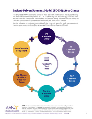
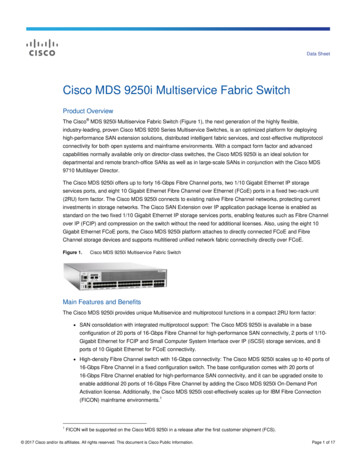
The RF safety distance is calculated based on each product type’s highest output powerconfiguration with no duplexer, redundant switching, or cable losses.Table 1-1 Antenna Gain vs. Minimum RF Safety DistanceAntenna GainRadio Module Equipped0–5 dBi5–10 dBi10–16.5 dBiSDM4 – FCC1.09 meters1.95 meters4.11 metersSDM4 – IC1.43 meters2.54 meters5.37 metersSDM9 – FCC0.99 meters1.76 meters3.73 metersSDM9 – IC1.29 meters2.30 meters4.87 metersLN41.43 meters2.54 meters5.07 metersLN91.08 meters1.92 meters3.82 meters(other models):Consult factory prior to operation.Not all frequency models available. Consult factory for available models.Antennas with gain greater than 16dBi have not been authorized for use with the EUT; and (b)installation of the EUT into portable applications with respect to RF compliance will requireSAR testing and Regulatory approval.CSA NoticeUnits (Both AC and DC supply versions) are permanently connected toProtective Earth, via ground stud on the unit enclosure back, where the finalinstallation is subject to acceptance of CSA International or the local inspection authority havingjurisdiction.Conditions of Acceptability:1. The equipment shall be installed indoors in a restricted accesslocation.2. Installation of the equipment and its modules shall be conducted bytrained personnel in accordance with the electrical code.3. This equipment is movable, Class I (earthed), pluggable Type A,using detachable power cords, intended for use on TN or TT powersystem for the AC power option.4. The DC power option shall be connected to an approved powersource with adequate protection, isolated from the mains byreinforced insulation.5. This product was certified for use on a 20A branch circuit for the ACpower option.MDS 05-6399A01, Rev. FMDS Master Station5
6.The AC socket outlet shall be installed near the equipment and shallbe easily accessible.7. The power supply cord must be disconnected from the appliance inletbefore removing any power supply from the chassis.8. CAUTION: THIS UNIT HAS MORE THAN ONE POWER SUPPLYCORD. DISCONNECT THE TWO POWER SUPPLY CORDSBEFORE SERVICING TO AVOID ELECTRIC SHOCK9. The equipment chassis shall be permanently grounded though a sizesix screw and a star toothed washer.10. The interior of the equipment is not for operator access.FCC Part 15 NoticeThis Equipment has been tested and found to comply with the limits for a Class A digital device,pursuant to Part 15 of the FCC Rules. These limits are designed to provide reasonable protectionagainst harmful interference when the equipment is operated in a commercial environment. Thisequipment generates, uses, and can radiate radio frequency energy and, if not installed and usedin accordance with the instruction manual, may cause harmful interference to radiocommunications. Operation of this equipment in a residential area is likely to cause harmfulinterference in which case users will be required to correct the interference at their own expense.This device complies with Part 15 of the FCC Rules. Operation is subject to the following twoconditions: (1) this device may not cause harmful interference, and (2) this device must acceptany interference received; including interference that may cause undesired operation.Warning: Changes or modifications not expressly approved by the manufacturer could void theuser’s authority to operate the equipmentFCC IDs of Available TransmittersAs of the printing date, the following identifiers are assigned to the modules listed below. For thelatest, official listings of all agency approvals, please contact your factory representative.Radio Desc.FCC IDIC IDWIFI ModuleM4Y-ZCN722MV13195A-ZCN722MV1LN 400Mhz ModuleE5MDS-LN400101D-LN400LN 700Mhz ModuleE5MDS-LN700n/aLN 900Mhz ModuleE5MDS-LN900101D-LN900SD 400Mhz ModuleE5MDS-SDM4101D-SDM4SD 900Mhz ModuleE5MDS-SDM9101D-SDM9Canada, IC ERP LimitsIC SRSP-501, 6.3.2. Limits the ERP to 125W for fixed point-to-point operation. For IC use, theantenna gain and Transmit power must be set to meet the ERP limit of 125W. This can beaccomplished by using the appropriate at antenna gain in combination with the RF powersettings6MDS Master StationMDS 05-6399A01, Rev. F
Environmental InformationThe equipment that you purchased has required the extraction and use of natural resources for itsproduction. Improper disposal may contaminate the environment and present a health risk due tohazardous substances contained within. To avoid dissemination of these substances into ourenvironment, and to diminish the demand on natural resources, we encourage you to use theappropriate recycling systems for disposal. These systems will reuse or recycle most of thematerials found in this equipment in a sound way. Please contact GE MDS or your supplier formore information on the proper disposal of this equipment.ISO 9001 RegistrationGE MDS adheres to this internationally-accepted quality system standard.Quality Policy StatementWe, the employees of GE MDS, are committed to achieving total customer satisfaction ineverything we do.Total Customer Satisfaction in: Conception, design, manufacture, and marketing of our products. Services and support we provide to our internal and external customers.Total Customer Satisfaction Achieved Through: Processes that are well documented and minimize variations. Partnering with suppliers who are committed to providing quality and service. Measuring our performance against customer expectations and industry leaders. Commitment to continuous improvement and employee involvement.Revision NoticeWhile every reasonable effort has been made to ensure the accuracy of this manual, productimprovements may result in minor differences between the manual and the product shipped toyou. If you have additional questions or need an exact specification for a product, please contactour Customer Service Team using the information at the back of this guide. In addition, manualupdates can often be found on our Web site at www.gemds.com.ESD NoticeTo prevent malfunction or damage to this radio, which may be caused by Electrostatic Discharge(ESD), the radio should be properly grounded by connection to the ground stud on the rearpanel. In addition, the installer or operator should follow proper ESD precautions, such astouching a grounded bare metal object to dissipate body charge, prior to connecting anddisconnecting cables on the front or rear panels.Open Source License DeclarationOrbit MCR products include Open Source Software. Usage is governed by the correspondinglicenses which are listed on the GE MDS Industrial Wireless website, under Orbit MCRSoftware/Firmware Downloads, Support Items and download license-declaration.txt.Upon request, in accordance with certain software license terms, GE will make available a copyof Open Source code contained in this product. This code is provided to you on an “as is” basis,MDS 05-6399A01, Rev. FMDS Master Station7
and GE makes no representations or warranties for the use of this code by you independent ofany GE provided software or services. For more information, contactgemds.techsupport@ge.com.8MDS Master StationMDS 05-6399A01, Rev. F
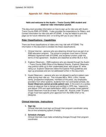
1.0INTRODUCTIONThe MDS Master Station is an advanced, flexible platform designed for the demandingrequirements of today’s industrial wireless networks. It represents the latest development in aline of MDS products that set the standards for wireless performance today. The Master Stationbuilds on this legacy with several innovative features, including a single compact chassis (2 RU),100% duty cycle operation (no cooling fans required), front panel access to all modules, anddrop-in compatibility with earlier MDS x790/x710 radio systems.As the central station in a wireless network, the Master Station provides uncompromisedperformance and reliability in mission-critical applications. It offers redundant protection of keymodules, automatic switchover in the event of a fault, and an external battery backup option forcontinued operation through temporary power losses. The Master Station mounts conveniently ina 19-inch rack cabinet, or may be used in shelf/tabletop configurations.Figure 1-1. MDS Master StationThe Master Station can be configured for a variety of service applications, including Point-toMultipoint SCADA, Point-to-Point links, broadband, and Cellular connectivity, depending on themodules installed and active in the chassis.In FCC part 90 SCADA service, the radio can function as a Master, Repeater, or Remote and iscapable of full duplex operation. Internal duplexer options are available, configured for use withor without an external notch filter. Provisions for connection to an external duplexer are alsoprovided. The Master Station is fully compatible with MDS PulseNET management software,which provides local or remote diagnosis and health reporting.1.1 Organization of ManualThis manual is intended for use by systems engineers, network administrators, and othersresponsible for the planning, installation, commissioning, use, and troubleshooting of thewireless system. The manual begins with an overall description of product features, and isfollowed by the steps required to install the unit and place it into normal operation.Following the installation procedures, sections are devoted to particular modules that may beinstalled in the chassis, including configuration settings for each of these units. Additionally,troubleshooting tips for resolving system difficulties are offered, as well as a technical referencesection with data on wiring, specifications, and spare parts that may be ordered for the unit.When installation and setup of the radio is complete, it is recommended that this guide be keptavailable for future reference at the installation site. Updated manuals, firmware, and othersupport documents may be obtained at any time from our website: www.gemds.com.MDS 05-6399A01, Rev. FMDS Master Station9
Related PublicationsIn addition to this manual, a companion Setup Guide is available for the MDS Master Station,Part No. 05-6398A01. The Setup Guide is focused on the essential steps for installation andstartup of the unit, and is designed to be used with this Technical Manual.The MDS Master Station Setup Guide, Part No. 05-6398A01 contains basic installation andstartup instructions for the product.All GE MDS user manuals and updates are available online at www.gemds.com.The MDS Master Station is built on the Orbit platform. Forreference information on advanced networking features available onthe local LAN Interface, refer to the MDS Orbit MCR TechnicalManual (05-6632A01). Note that not all features are supported bythe Master Station or the SD Radio Module. Wireless networkingcapabilities are limited by the narrowband channel and thecapabilities of the remote radio.10MDS Master StationMDS 05-6399A01, Rev. F
2.0KEY PRODUCT FEATURESAs a licensed, long range IP/Ethernet and serial communications device, the Master Stationexceeds industry standards for reliability and performance in wireless networks. Listed below areseveral key features and benefits of the product, and these are available with the appropriatemodules installed and configured in the chassis. Drop-in replacement for earlier MDS x790 Master Stations, including support for allmodem types Backward compatibility with all legacy MDS x710 Series remote transceivers (A and Bmodems) Compatible with next generation MDS narrowband wireless LN radios, with enhancedthroughput and security. (When equipped with LN radio cards) May be operated as a Master Station, repeater, or remote radio Supports use of MDS PulseNET Network Management Software Software-configurable via a built-in web-based device manager—no manual adjustmentsrequired Firmware-upgradeable for future improvements and functionality enhancements Available encryption of payload data (AES 128-bit), for networks using all-SD radios Dual serial functionali
MDS 05-6399A01, Rev. F MDS Master Station 5 The RF safety distance is calculated based on each product type's highest output power configuration with no duplexer, redundant switching, or cable losses. Table 1-1 Antenna Gain vs. Minimum RF Safety Distance Radio Module Equipped Antenna Gain 0-5 dBi 5-10 dBi 10-16.5 dBi