Transcription
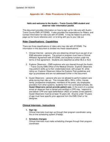
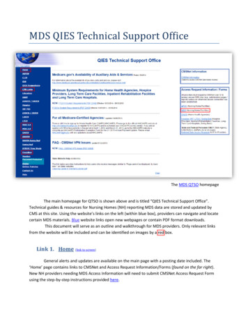
MDS Master StationSetup GuideINTRODUCTIONTable 1: Module Descriptions - Redundant StationThe MDS Master Station serves as a central station in a multiple address system (MAS) wireless network. It provides long range, duplex(or simplex) communication between a control point and associatedremotes. It is fully redundant for mission-critical applications, and is acompatible replacement for older MDS x790 Master Stations whenordered with the appropriate network interface modules.The MDS Master Station works with a wide array of wireless equipment, including MDS SD Transceivers, legacy MDS x710 radios, MDSLN radios, and additional wireless options, depending on the modulesinstalled in the chassis.ModuleIDFunctionPower Supply 1,Power Supply 2VariesInput power supply. In a redundantconfiguration, both supplies work intandem and are independent of whichradio is active.Platform Manager6834Provides management and data interfacefunctions.Radio A,6846Single or redundant SD Master radios(SDM9, SDM4), or LN radio modules6847Redundant—Active radio relay andalarm/audio interface.6848Non-redundant—Alarm and audiointerface.6837Internal RF duplexer (if equipped)Radio BAlarm/RelayDuplexerRelated DocumentationFigure 1: MDS Master StationAll modules are installed on slide-in assemblies, accessible from thefront of the unit. A protective cover on the unit’s face slides off, allowingaccess to the modules and all interface connectors. In addition tocommunication modules, up to two power supply units may be installedand are available to suit a wide range of AC and DC power requirements.Each module is secured to the chassis with knurled fasteners for easychanges, when required. Figure 2 shows a common configuration ofinstalled modules.IMPORTANT: To ensure proper heat-sink engagement, the knurledfasteners must be tightened with a screw driver to at least 10inch-pounds (approximately ¼ turn past hand tight).Supply 1 (DC)Supply 2 (AC)Platform ManagerRadio ARadio BAlarm/RelayIn addition to this setup guide, the MDS Master Station TechnicalManual (05-6399A01) provides guidance on system design, advancedconfiguration, and maintenance. The Technical Manual is available topersonnel involved in the design, commissioning and maintenance ofthe network. Electronic copies of the latest user documents and supportfiles are available free of charge at www.gemds.com.Options and AccessoriesThe MDS Master Station may be equipped with optional battery backupand a variety of duplexer and module options. Contact your factoryrepresentative for information on any of these options.In addition, GE MDS offers an Accessories Selection Guide listingadditional items that may be used with many of our products. Contactyour factory representative or visit www.gemds.com for the latestcopy.Typical ApplicationDuplexerFigure 3 on the following page shows a common arrangement of theMDS Master Station as used in a licensed narrowband network. Thesystem shows both MCR and ECR transceivers in use.Depending on order options, the MDS Master Station can communicatewith remotes employing Ethernet signaling, serial signaling, or a mix ofboth.Figure 2: Front Panel Connectors & Indicators(Front cover removed)Master Station modules are factory installed and cabled. Table 1:Module Descriptions - Redundant Station describes each moduleinstalled in a redundant configuration, from left to right. For anon-redundant configuration, blank plates are used in place of theredundant power supply and radio modules and a non-redundant version of the Alarm/Relay module is installed.The MDS Master Station supports Ethernet or serial polling dependingon order options. A host computer may be connected to the appropriateport on the chassis (LAN for Ethernet; COM1/2 for serial signaling).Configuration of the unit is performed through a web interface. Thisrequires a LAN connection to one of the Ethernet ports on the PlatformManager module. In addition, a command line interface (CLI) is available through the mini USB port using the proper USB drivers available atwww.gemds.com.05-6398A01, Rev. H.1MDS Master Station Setup Guide1
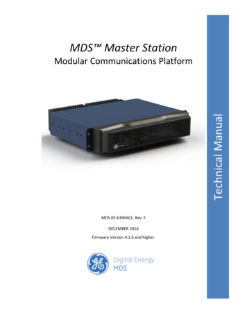
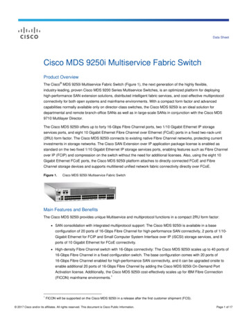
Connector 1:TX/RX Antenna PortKnockout coversinstalled on unusedportsFigure 5: Internal Duplexer (or internal T/R switch),Single N connectorConnector 1:TX Output PortConnector 2:RX Input PortFigure 3: Licensed Narrowband Application ExampleFigure 6: External duplexer or dual antennas(TX and RX ports pass directly through)INSTALLATION3. Install the Data Interface Cabling. Interface connections areRefer to the figures which follow for these steps, as required:1. Mount the unit. The unit may be rack-mounted (2U high) in a19-inch rack cabinet or may be placed on any sturdy tabletop orother flat surface. The installation site should be free of excessivedust, and should have adequate ventilation. The chassis should bepositioned so that all interface cabling will reach the required connectors.When rack mounting, the rack ears can be installed in one of threepositions to allow flexibility in the mounted depth of the chassis. Theunit should be mounted so as to maximize airflow around the rearheat sink.2. Connect Antenna Feed-lines. All coaxial antenna connections aremade to the Type-N connectors on the rear of the unit. Figure 4,Figure 5, and Figure 6 illustrate the antenna options available;Connector 1:TX/RX Antenna PortConnector 2:RX Output to externalnotch filterConnector 3:RX Input from externalnotch filtermade to the front of the Platform Manager module. Typical connections for most sites include: Serial Data—Attach data equipment to the front panel COM1 orCOM2 port. By default, the COM2 port is set for managementand must be configured for data before connecting data equipment. The unit is hardwired as a DCE device, thus astraight-through Ethernet cable may be used in most cases(DB9-F to RJ-45 connector, GE MDS part no. 73-2434A12). Ethernet LAN—Attach data equipment to the ETH1 and/orETH2 port. The auto-sensing MDIX feature allows either astraight-through or crossover cable to be used.Where applicable in the steps that follow, secure all cable connectionswith the locking screws provided.4. Connect Primary Power—The Master Station is powered usingone or two power supply modules that work in tandem. The modules may be AC, DC, or a combination of both. The following tableslist each type and key operating parameters.Table 2: AC Power Supply ModuleModuleInput PowerCurrent Rating6755100-264 VAC, 50/60 Hz120W Max.All DC power supply modules have chassis isolated inputs and adiode bridge for floating ground, positive ground, or negativeground installations. These modules include a keyed power connector with screw-terminals. Power supply connections must beless than 3 meters from the source to the terminals. Strip the wireleads to 6mm (1/4 inch) and insert them into the wire ports provided. Be sure to observe the polarity shown below. Tighten the binding screws securely and insert the connector into the module.Figure 4: Internal Duplexer, Triple N connectorsTable 3: DC Power Supply ModulesModule2Input PowerCurrent Rating6843 /- 12-30 VDC10 A Max6844 /- 36-75 VDC3.5 A MaxMDS Master Station Setup Guide05-6398A01, Rev. H.1
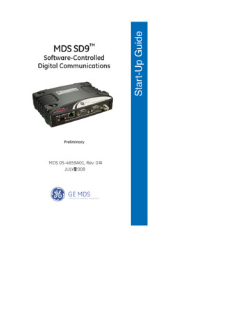
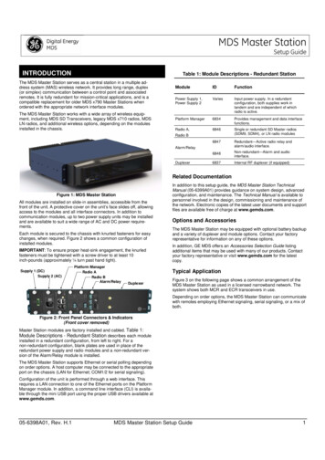
6845 /- 75-140 VDC2 A Max /- VDC InputCenter Terminal;Chassis ground1. Open a web browser and navigate to the IP address of the unit(default Ethernet IP address is 192.168.1.1). The initial sign-inprompt appears.2. Enter the username and password (admin is the default entry forboth fields). Click Sign In. Upon successful login, the DeviceOverview page appears.3. For general configuration, the Initial Setup Wizard will appear andprovide guidance in typical setups. This is disabled after the initialsetup but may be re-run at any time by accessing the Wizards linkon the left side of the screen, and clicking Initial Setup.Key items that should be reviewed and/or set for the radio are: /- VDC Input Create one-time programmable passwords for unit recovery Change login passwords (to maintain security) Evaluate default factory configuration and lock the unit down tothe required security levelFigure 7: DC Power Connector5. Connect a PC for Configuration (LAN or USB port). This prepares the Master Station for programming of desired operating parameters. Configuration is further described in Section 0 SOFTWARE CONFIGURATION.NOTEIf serial-based cabling is used for configuration, an adaptermay be required at the PC, as many PCs do not offer a serialport. In such cases, a USB-to-Serial adapter (with appropriate driver software) may be used. These adapters are available from a number of manufacturers.6. Redundant Units—The Alarm/Relay module includes a manualoverride toggle switch, which can be set into one of three positionsto associate it with a particular radio. The toggle switch is locking,and must be pulled out to change positions. Switch functions are asfollows:Up—Radio A;Down—Radio B;4. If your MDS master station was ordered with SD network interfaces,select the SD Configuration Wizard, which steps you through initial SD Radio Module configuration. Key items that should be reviewed and/or set include: Frequency planModem selectionKeying modeSerial data interface configurationEncryption settings5. For additional SD radio configuration and status options, navigateto SDMS Configuration as follows: Expand ‘Interfaces‘ on the left hand menu, and select theinterface named ‘sdms’ (SD Master Station):Center—AutomaticWhen the switch is set to Automatic, the active radio is determinedby radio module presence and alarm status. If only one radio module is installed (A or B) it is recommended that the switch be set toA or B, as appropriate.7. Radio, Alarm/Relay, and Duplexer Connections—TheAlarm/Relay module provides two alarm outputs, one for major andone for minor alarms. This module also provides TX/RX audio, PTT(TX keying), and analog RSSI connections when used in conjunction with compatible radio interfaces. See Section 0ALARM/AUDIO PINOUT for pin-out connections.All other required connections on the front of the unit are cabled atthe factory per ordered options.SOFTWARE CONFIGURATION Redundant radios share a common configuration and aremanaged simultaneously through the Basic Config, Advanced Config, or Actions tabs.6. If your MDS master station was ordered with LN interfaces, LNconfiguration can be located under the interface named “lnms” (LNMaster Station), which by default, is a member of the ‘bridge’ interface:In the following steps, you will log into the unit’s configuration systemand set the basic operating parameters for the unit.NOTEConsult your System Administrator if you are unsureof the proper configuration settings for your network.Configuration via Web Device ManagerThe configuration PC may be connected to the unit by WiFi (futurefeature), USB, or Ethernet. The following steps describe a configurationusing the GE MDS Device Manager running on the unit. The DeviceManager is accessible through ETH1 or ETH2 using a web browser.Minimum browser requirements: IE10 or later, Chrome, Firefox, orSafari.05-6398A01, Rev. H.1MDS Master Station Setup Guide3
Redundant radios share a common configuration and aremanaged simultaneously through the Basic Config, Advanced Config, or Actions tabs.Platform ManagerALARMFlashing — Alarmed (SD Master)SD RadioPWR/ALARMOn — Power appliedFlashing — Alarmed radioSD RadioACTIVEOn — ActiveOff — StandbySD RadioTXOn — TransmittingOff — No DataSD RadioRXOn — ReceivingOff — No DataLN RadioPWR/ALARMOn (Green) — Power appliedFlashing (Red) — Alarmed radioLN RadioACTIVEOn (Green) — Active – linkOn (Red) — Active – no linkOff — Standby7. Connect a PC to the unit's USB port and establish a consoleterminal session using a serial communications program.LN RadioTXOn — TransmittingOff — No Data8. Press the ENTER key to receive the login prompt; the USB interface will auto-baud. The COM LED flashes to indicate data communications.LN RadioRXOn — ReceivingOff — No DataConfiguration via Command Line (CLI)A scriptable command-line interface is accessible through the Ethernetport using Secure Shell (SSH) terminal, COM2 Serial Port, or throughthe unit’s USB interface. For enhanced security, the unit does notsupport Telnet configuration. The steps below describe a cabled USBconnection and assume the proper drivers have been installed. Driversfor Microsoft Windows are located free of charge at www.gemds.comin the ‘Support Items’ folder under the Software/Firmware Downloadsection of the MDS Master Station product page. Drivers are notneeded for Mac OSX or Linux.9. Enter the Username (admin is the default username) and pressENTER.10. At the Password prompt, enter the password (admin is the defaultpassword). Press ENTER. Upon successful login, the connectionmessage appears.Alarm/RelayALARM MAJOn — Major AlarmAlarm/RelayALARM MINOn — Minor AlarmAlarm/RelayACT AOn — Radio A ActiveOff — Radio A StandbyAlarm/RelayACT BOn — Radio B ActiveOff — Radio B Standby11. Enter the configuration mode by typing configure followed by theENTER key.6. Review and configure all key settings for the required application.Built-in help is available by pressing the Tab key. A summary of allunit settings may be viewed by entering the % show detailscommand.Tab-completion is a powerful feature that provides assistance whentyping commands in the CLI. Depending on the text that was alreadyentered, tab-completion displays different possible completions. Whenthe Tab key is pressed and no text has been entered, the CLI shows allpossible commands that can be typed.COM1/COM2 REFERENCEThe COM port is commonly used to connect an external DTE telemetrydevice to the unit, supporting either the RS-232 or RS-485 (balanced)format, depending on how the device is configured. The unit supportsdata rates of 300, 1200, 2400, 4800, 9600, 19200, 38400, 57600, and115200 bps (asynchronous data only).This connector mates with a standard RJ-45 plug (see Figure 8)available from many electronics parts distributors.Pin Descriptions—RS-232 ModeKey items that should be reviewed or set for the unit are as follows: Create one-time programmable passwords for unit recovery Change login passwords (to maintain security) Evaluate default factory configuration and lock the unit down toPin descriptions for the COM connector in RS-232 mode are shown inTable 5 and Table 6 on the following page. Note that the unit is hardwired as a DCE device. Refer to the Technical Manual for RS-422/485descriptions. (Note: RS-485 supported on COM2 only.)the required security level Radio configuration, including TX/RX frequency plan, modemselection, keying mode, encryption, and serial data interfaceconfiguration.Refer to the Technical Manual for details on the above items.Figure 8: COM Connector (RJ-45)As viewed from outside the unit7. When finished, log out of the console session and disconnect thePC from the Master Station.Table 5: COM1 Pin-out - Default Data PortIN-SERVICE OPERATIONIn-service operation of the MDS Master Station is completely automatic.The only operator actions required are to apply power and check themodule LEDs for proper indications as shown in Table 4: ModuleLED Descriptions.Table 4: Module LED Descriptions4ModuleLED NameFunctionPlatform ManagerPWROn — Power appliedFlash — System bootupPlatform ManagerPWR &ALARM ONSystem Initialization (pre-bootup)Pin#Input/OutputPin Description1OUTDSR (Data Set Ready)2OUTDCD (Data Carrier Detect)3INDTR (Data Terminal Ready)4GroundConnects to chassis ground (negative supply)5OUTRXD (Received Data)—Supplies received datato the connected device6INTXD (Transmitted Data)—Accepts TX datafrom the connected deviceMDS Master Station Setup Guide05-6398A01, Rev. H.1
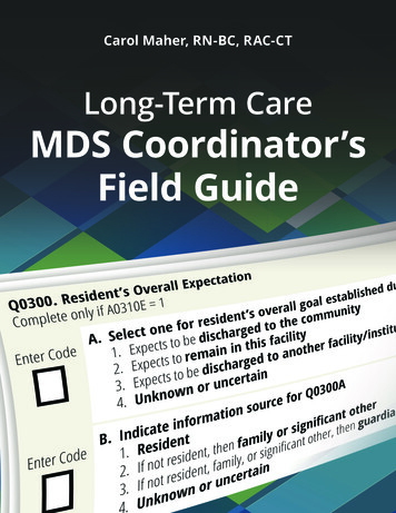
Redundant Units7OUTCTS (Clear to Send)8INRTS (Request to Send)Table 6: COM2 Pin-out - Default Console PortPin#Input/OutputPin Description1Reserved-- (Do not connect)2Reserved-- (Do not connect)3Reserved-- (Do not connect)4GroundConnects to chassis ground (negative supply)5OUTRXD (Received Data)—Supplies received datato the connected device6INTXD (Transmitted Data)—Accepts TX datafrom the connected device7OUTCTS (Clear to Send)8INRTS (Request to Send)The active radio can be identified by the corresponding LED on thealarm/relay module as well as the active LED on the radio module. Theactive unit is normally selected automatically. For troubleshooting, thetoggle switch can be used to manually set the active radio. Alternatively, the switch can remain in the automatic position and the active radiocan be selected via the Device Manger UI.Technical AssistanceFactory technical assistance is available by contacting GE MDS duringbusiness hours (8:30 AM to 6:00 PM Eastern Time). For telephoneassistance, call (585) 241-5510, or visit our website at www.gemds.comfor additional contact options.Refer also to the Regulatory & Product Information Sheet supplied withthese instructions.VIDEO TUTORIALSALARM/AUDIO PINOUTThe ALARM/AUDIO Interface on the Alarm/Relay module providesaudio signaling and alarm outputs as shown in Figure 9. Note: PTT,Analog RSSI, and Audio connections are only available when used withSD interfaces. 12v612Analog RSSIPTT511Major Alarm ContactRx Audio -410Major Alarm ContactRx Audio 39Minor Alarm ContactTx Audio -28Minor Alarm ContactTx Audio 17GroundGE Industrial CommunicationsYouTube Learning & DevelopmentInvisible place holderFigure 9: Alarm/Audio Connections(As viewed from front of the Alarm/Relay module)TROUBLESHOOTINGIf trouble occurs with the unit, verify that it meets the basic requirementslisted below. These items should be checked prior to starting any detailed troubleshooting or calling for assistance. All units must have:Within YouTube https://www.youtube.com/ search onMDS Master Station Adequate and stable primary power Secure cable and wiring connections Proper configuration for the applicationLEDsThe LEDs on the front of installed modules (Table 4: Module LEDDescriptions) provide useful information when troubleshooting. Powerand alarm indicators are provided on Platform Manager, Radio, andAlarm/Relay modules. Radio Modules also have TX/RX LEDs to showwireless activity.05-6398A01, Rev. H.1MDS Master Station Setup Guide5
Regulatory & Product InformationSheet—MDS Master StationFCC Part 15 NoticeThis Equipment has been tested and found to comply with the limits fora Class A digital device, pursuant to Part 15 of the FCC Rules. Theselimits are designed to provide reasonable protection against harmfulinterference when the equipment is operated in a commercial environment. This equipment generates, uses, and can radiate radio frequency energy and, if not installed and used in accordance with theinstruction manual, may cause harmful interference to radio communications.Operation of this equipment in a residential area is likely to causeharmful interference in which case users will be required to correct theinterference at their own expense.This device complies with Part 15 of the FCC Rules. Operation is subject to the following two conditions: (1) this device may not causeharmful interference, and (2) this device must accept any interferencereceived; including interference that may cause undesired operation.Warning: Changes or modifications not expressly approved by themanufacturer could void the user’s authority to operate the equipmentServicing PrecautionsWhen servicing energized equipment, be sure to wear appropriatePersonal Protective Equipment (PPE). During internal service, situations could arise where objects accidentally contact or short circuitcomponents and the appropriate PPE would alleviate or decrease theseverity of potential injury. When servicing radios, all workplace regulations and other applicable standards for live electrical work should befollowed to ensure personal safety.Manual Revision and AccuracyThis manual was prepared to cover a specific version of firmware code.Accordingly, some screens and features may differ from the actual unityou are working with. While every reasonable effort has been made toensure the accuracy of this publication, product improvements may alsoresult in minor differences between the manual and the product shippedto you. If you have additional questions or need an exact specificationfor a product, please contact GE MDS, using the information at theback of this guide.In addition, manual updates can be found on our web site atwww.gemds.com.Environmental InformationCanada, IC ERP LimitsIC SRSP-501, 6.3.2. Limits the ERP to 125W for fixed point-to-pointoperation. For IC use the antenna gain and Transmit power must be setto meet the ERP limit of 125W. This can be accomplished by usingthe appropriate at antenna gain in combination with the RF power settings.RF Exposure NoticeTo comply with RF exposure requirements, the antenna shall be installed to ensure a minimum separation distance shown below frompersons. The antenna may not be collocated or operated in conjunctionwith other transmitting devices. To reduce potential radio interference toother users, the antenna type and its gain should be so chosen that theEquivalent Isotropically Radiated Power (EIRP) is not more than thatpermitted for successful communication.Only approved antennas may be used on the unit's RF output connectors, as listed below. The use of non-approved antennas may resultin a violation of FCC rules, and subject the user to FCC enforcementaction.Table - Antenna Gain vs. Minimum RF Safety DistanceAntenna Gain0–5 dBi5–10 dBi10–16.5 dBiSafety Distance400 MHz variant – FCC1.091.954.11metersmetersmetersSafety Distance400 MHz variant – IC1.432.545.37metersmetersmetersSafety Distance0.991.763.73900 MHz variant – FCCmetersmetersmetersSafety Distance900 MHz variant - IC1.292.304.87metersmetersmetersSafety Distance (othermodels):The manufacture of this equipment has required the extraction and useof natural resources. Improper disposal may contaminate the environment and present a health risk due to hazardous substances containedwithin. To avoid dissemination of these substances into our environment and to limit the demand on natural resources, we encourage youto use the appropriate recycling systems for disposal. These systemswill reuse or recycle most of the materials found in this equipment in asound way. Please contact GE MDS or your supplier for more information on the proper disposal of this equipment.Product Test Data SheetsTest Data Sheets showing the original factory test results for this unitare available upon request from the GE MDS Quality Leader. Contactthe factory using the information at the back of this manual. Serialnumbers must be provided for each product where a Test Data Sheet isrequired.Grounding RequirementsTo minimize the chance of damage to the unit and connected equipment, a safety ground (NEC Class 2 compliant) is recommended whichbonds the antenna system, chassis, power supply and connected dataequipment to a single-point ground, keeping all ground leads as shortas possible.Normally, the unit is adequately grounded if the supplied mountingbrackets are used to mount it to a well-grounded metal surface. If theunit is not mounted to a grounded surface, it is recommended that asafety ground wire be attached to one of the mounting brackets or ascrew on the enclosure.The use of a lightning protector is recommended where the antennacable enters the building. Bond the protector to the tower/supportground, if possible. All grounds and cabling must comply with applicable codes and regulations.Consult factory prior to operation.Antennas with gain greater than 16dBi have not been authorized foruse with the EUT; and (b) installation of the EUT into portable applications with respect to RF compliance will require SAR testing and Regulatory approval.6MDS Master Station Setup Guide05-6398A01, Rev. H.1
Evaluate default factory configuration and lock the unit down to the required security level 4. If your MDS master station was ordered with SD network interfaces, select the SD Configuration Wizard , which steps you through in-itial SD Radio Module configuration. Key items that should be re-viewed and/or set include: Frequency plan