Transcription
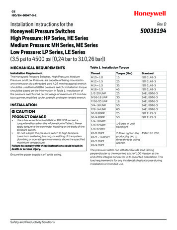
CEIEC/EN-60947-5-1Installation Instructions for theHoneywell Pressure SwitchesHigh Pressure: HP Series, HE SeriesMedium Pressure: MH Series, ME SeriesLow Pressure: LP Series, LE Series(3.5 psi to 4500 psi [0,24 bar to 310,26 bar])Rev. D50038194MECHANICAL REQUIREMENTSTable 1. Installation TorqueInstallation RequirementThe Honeywell Pressure Switches, High Pressure, MediumPressure, and Low Pressure, are capable of being mounted inany orientation via a threaded port. A 27 mm hexagonal wrenchshould be used to install the pressure switch. Installation torqueshould be based on the information in Table 1. Installation ofthe pressure switch shall permit usage of maximum 27 mm hexbox spanner, modified socket wrench, and open-ended wrench.ThreadTorque (Nm)StandardM10 1.015ISO 6149-3M12 1.525ISO 6149-3M14 1.535ISO 6149-3M18 1.545ISO 6149-31/2-20 UNF25SAE J1926-39/16-18 UNF30SAE J1926-37/16-20 UNF18SAE J1926-33/4-16 UNF50SAE J1926-3, CAUTION7/8-14 UNF60SAE J1926-3PRODUCT DAMAGEG1/8 BSPP25ISO 1179-3G1/4 BSPP50ISO 1179-3INSTALLATION Use a hex wrench for installation. DO NOT exceed atorque level based on the information in Table 1. Neverapply torque to the connector housing or the body of thepressure switch. Do not subject the pressure switch to high temperatures from soldering, brazing, or welding of the systemplumbing or operating environments above the specifiedmaximum temperature.Failure to comply with these instructions could result indeath or serious injury.Ensure the power supply is off while wiring.Safety and Productivity Solutions1/4-18 NPT1/8-27 NPT1/8-27 PTFR1/8 BSPTR1/2 - 14 BSPTR1/2 BSPTR1/4 BSPT1-Screw in untilhandtight2-Then tighten the ASME B 1.20.1product by two tothree threads usingwrenchThe pressure switch can withstand a side load (actingperpendicular to the mounted axis) of 100 Newton at theend of the integral connector in its mounted orientation. Thisload requirement is for any incidental physical abuse duringinstallation or intended use.
Honeywell Pressure SwitchesOVERPRESSURERev. D50038194WIRING INSTRUCTIONS, CAUTIONNOTICEPRODUCT DAMAGETo ensure proper environmental sealing and electricalconnections when using a connector, follow the connectormanufacturer’s installation guidelines. All terminal cavitiesmust be sealed using the correct wire gauge and seal combination. If only two leads are used, any additional terminalcavities should be sealed per the connector manufacturer’sinstallation guide. Honeywell recommends using a crimpingtool for crimping wires to the connector terminals. Contactthe individual connector manufacturer for connector wiring. Do not exceed the operating pressure.Failure to comply with these instructions could result indeath or serious injury.If the operating pressure is exceeded, the life of the Honeywellpressure switch may be reduced and electrical failure mayoccur. Both static and dynamic over-pressuring must beconsidered, particularly in hydraulic system applications.Hydraulic pressure fluctuations can have very high and rapidpressure spikes, as in a water hammer effect. The high pressureversions (HP Series, HE Series) have a snubber feature built-into reduce the peak pressure applied to the pressure switch. Themedium and low pressure versions (ME Series, LP Series, LESeries) do not employ this feature.If system pressure pulses are expected, choose a pressureswitch with a proof pressure rating high enough to allowoperation at the highest expected pressure spikes.MEDIA COMPATIBILITY, CAUTIONPRODUCT DAMAGE Use non-abrasive, chemically compatible media to prevent damage to the pressure switch.Failure to comply with these instructions could result indeath or serious injury.The pressure switch’s fluid path is an assembly of zincplated steel, stainless steel, DuPont Teflon -coated Kapton ,and nitrite. The Series is compatible with a wide variety ofpetroleum-based fluids, air, water, and mineral oil-based brakefluid. Please confirm your media compatibility or speak with aHoneywell Application Engineer.2 sensing.honeywell.comFUNCTIONAL TESTConnect the pressure switch to the pressure source (off).Based on the pressure switch’s specified normally open (NO) ornormally closed (NC) output, connect the electrical terminationto a dc voltage supply. With no pressure on the pressure switch,turn on the power supply and ensure that the pressure switchis in the correct NO or NC position. Apply the appropriate setpoint pressure to ensure that the NO or NC contact position ofthe switch will switch over.
Honeywell Pressure SwitchesRev. D50038194Table 1. SpecificationsCharacteristicProductlength (variousterminations)Product length(blade)Product length (#832 screws)Product length(Metripack)Hex sizeEase of installationSnap-action switchHP SeriesHE SeriesME SeriesMH SeriesLP SeriesLE Seriessee pages 5 and 6see page 5see page 8see page 7see page 9see page 9see pages 5 and 6see page 5see page 8see page 7see page 9see page 9see pages 5 and 6see page 5see page 8see page 7see page 9see page 9see pages 5 and 6see page 5see page 8see page 7see page 9see page 927 mm27 mm27 mm27 mm27 mm27 mmbox spannerbox spannerbox spannerbox spannerbox spannerbox spanneryesyesnonoyesnoSet point1 range100 psi to 4500 psi150 psi to 4500 psi25 psi to 350 psi40 psi to 500 psi3.5 psi to 150 psi3.5 psi to 150 psiSet point ranges6 (Base Style A)7 (Base Style B)64444100 psi to 150 psi ( 10 %);150 psi to 500 psi ( 6 %);501 psi to 4000 psi( 3.5 %);4000 psi to 4500 psi( 2 %)150 psi to 1000 psi( 14%);1000 psi to2000 psi( 12 %);2000 psi to4000 psi( 11 %); 4000 psi ( 10 %)25 psi to 50 psi( 3 psi); 50 psi to 100 psi ( 7 psi); 100 psi to 150 psi( 10 psi); 150 psi to 250 psi( 13 psi); 250 psi to 350 psi( 16 psi)n/an/a25 psi to 50 psi(20 psi); 50 psi to 100 psi (30 psi); 100 psi to 150 psi(40 psi); 150 psi to 250 psi(50 psi); 250 psi to 350 psi(60 psi)5,000 psi max.5,000 psi max.500 psi max.Proof pressure310,000 psi (Base Style A)6,500 psi (Base Style B)10,000 psiHysteresis5 % to 55 %(based on set point range)Burst pressure4Set pointaccuracy @ 25 C(before test)40 psi to 70 psi( 7 psi); 70 psi to 130 psi ( 10psi); 130 psi to 200 psi( 15 psi); 200 psi to 280 psi( 20 psi); 280 psi to 350 psi( 30 psi); 350 psi to 500 psi( 40 psi)40 psi to 70 psi( 6 psi); 70 psi to 130 psi ( 10psi); 130 psi to 200 psi ( 15psi); 200 psi to 280 psi ( 20psi); 280 psi to 350 psi ( 30psi); 350 psi to 500 psi ( 40psi)3.5 psi to 10 psi ( 1 psi); 10 psi to 50 psi ( 3 psi); 50 psi to 100 psi ( 7 psi); 100 psi to 150 psi ( 10 psi)n/a3.5 psi to 10 psi( 2.8 psi); 10 psi to 50 psi( 14 psi); 50 psi to 100 psi( 38 psi); 100 psi to 150 psi( 40 psi)600 psi max.250 psi max.250 psi max.4,000 psi6,000 psi500 psi500 psi3 % to 65 %(based on set point range)n/an/a5 % to 55 %(based on set point range)n/a20,000 psi (Base Style A);9,000 psi (Base Style B)20,000 psi8,000 psi9,000 psi1250 psi1250 psiCurrent rating(resistive)5 A at 250 Vac5 A at 24 Vdc3 A at 250 Vac3 A at 24 Vdc7.5 mA to 3 A,24 Vdc and 250 Vac100 mA to 3 A max.7.5 mA to 5 A,24 Vdc and 250 Vac7.5 mA to 3 A,24 Vdc and 250 VacCurrent rating(inductive)5 A at 115 Vac (SX rating);3 A at 28 Vdcn/an/an/a1 A at 28 Vdcn/aRated thermalcurrent5A3A3An/a5A3ARated insulationvoltage28 V28 V28 Vn/a28 V28 VAverage deadbandmax.Operating pressure2Short-circuitprotective device ctype max. ratingClass J fuse (10 A, 600 V)n/aClass J fuse (10 A, 600 V)Port Style C: Switches less than 975 psi will use Base Style B; switches greater than 975 psi will use Base Style A.Port Styles F and G: Switches less than 350 psi will use Base Style B; switches greater than 350 psi will use Base Style A.Port Styles A, B, E, M, P, T, and Y will use Base Style B.Switches less than 150 psi will only use Base Style B.8Safety and Productivity Solutions3
Honeywell Pressure SwitchesRev. D50038194Table 1. Specifications (continued)CharacteristicHP SeriesHE SeriesME SeriesMH SeriesLP SeriesLE Series1000 A1000 AConditional shortcircuit current1000 An/aPollution degree3 (macro environment)n/aTemperature ratingMediaconnectionPressure ports-40 C to 120 C[-40 F to 248 F]-40 C to 85 C[-40 F to 185 F]multiple ports availablemultiple ports availableCircuit forms5SPDT, SPST - NO/NCSmart pressure-40 C to 120 C [-40 F to 248 F]multiple ports availableA 1/4-18 NPTB 1/8-27 NPTC 1/2-20 UNFD 1/8-27 PTFE M12 1.5F M14 1.5G 9/16-18 UNFH 3/4-16 UNFJ G1/8 BSPPM 7/16-20 UNFR R1/8 BSPTT M10 1.0V R1/2 BSPTY G1/4 BSPPZ R1/4 BSPTC 1/2-20 UNFF M14 1.5Refer to product nomencla- G 9/16-18 UNFture for pressure port types. H 3/4-16 UNFK M18 1.5N 7/8-14 UNF3 (macro environment)SPDT, SPST - NO/NCsingle- or dual-resistor topology availableA 1/4-18 NPTB 1/8-27 NPTC 1/2-20 UNFD 1/8-27 PTFE M12 1.5F M14 1.5G 9/16-18 UNFH 3/4-16 UNFJ G1/8 BSPPL 3/8-24 UNFM 7/16-20 UNFP 1/2-14 NPTR R1/8 BSPTT M10 1.0V R1/2 BSPTY G1/4 BSPPZ R1/4 BSPTSPST - NO/NCA 1/4-18 NPTB 1/8-27 NPTC 1/2-20 UNFD 1/8-27 PTFE M12 1.5F M14 1.5G 9/16-18 UNFH 3/4-16 UNFJ G1/8 BSPPM 7/16-20 UNFR R1/8 BSPTT M10 1.0V R1/2 BSPTY G1/4 BSPPZ R1/4 BSPTSPDT, SPST - NO/NC–A 1/4-18 NPTB 1/8-27 NPTC 1/2-20 UNFD 1/8-27 PTFE M12 1.5F M14 1.5G 9/16-18 UNFH 3/4-16 UNFJ G1/8 BSPPM 7/16-20 UNFR R1/8 BSPTT M10 1.0V R1/2 BSPTY G1/4 BSPPZ R1/4 BSPTSPDT, SPST - NO/NCsingle- or dual-resistor topology available2 million (Base A)1 million (Base B)1 million1 million1 million2 million1 millionAgency approvals (special useswitches)––––––Agency approvals(other)CECECECECECEField adjustability6nonoyesyesyesyesSpike dampeningyesIP67 (connecetors)IP67 (wire/Base A)IP69K (wire/Base B)IP00 (blade/screw)yesnonononoIP67 (connectors)IP00 (blade/screw)IP67 (connectors)IP67 (wire out)IP00 (blade/screw)IP67 (connectors)IP00 (blade/screw)IP67 (connectors)IP67 (wire out)IP00 (blade/screw)IP67 (connectors)IP67 (wire out)IP00 (blade/screw)LifeIngress protection7swept sine: 10 Hz to 2000 Hz at 15 g, 20 min/sweep; 8 hours in each axisrandom: 5 Hz to 2000 Hz, 8 hours/axis; 14,88 g-RMS, each axisVibration resistanceShock resistance500 m/sec2, 11 mSEC, 100 shocks / axisWetted part(diaphragm)Wetted part (piston)WeightContactsProduct finish500 m/sec2, 11 mSECn/aKapton(Teflon coated)Nitrile/EPDM/LTNBKapton (Teflon coated)Tefzel nitrile o-ring, steel pistonnitrile or EPDM o-ringnitrile or EPDM o-ringnitrile or EPDM o-ringnitrile or EPDM o-ring133 g [4.7 oz] (Base Style A)178 g [6.28 oz] (Base Style B)53 g [1.9 oz]53 g [1.9 oz]58 g [2.0 oz]53 g [1.9 oz] silver / gold inlaysilvergold platedgold platedgold platedgold platedzinc platingzinc platingzinc platingzinc platingzinc platingzinc platingSet point: Point at which switch actuates or de-actuates2Operating pressure: Maximum normal system operating pressure3Proof pressure: Maximum pressure that the switch can handle while it maintains set point accuracy. Intermittent spikes to this level are acceptable.4Burst pressure: Point of complete switch failure5SPST: Single pole, single throw. SPDT: Single pole, double throw. NO: Normally open. NC: Normally closed.6Field adjustability only available with AA, BA, CA, and DA (SPST only) terminations.7IP00 for AA and BA terminations.14 sensing.honeywell.com
Honeywell Pressure SwitchesRev. D50038194Table 2. TerminationsSeriesAvailable TerminationsHP, HE, ME,LP, LEAA Spade TerminalsBA Screw TerminalsCA Deutsch DT04-3P-E005 (3-Pin Connector)DA Amp Super Seal 1.5 - 282105-1 (3-Pin Connector)EA 10-inch Cable, 18 AWG (Wire Out, No Connector)FA 10-inch Cable w/Deutsch DT04-3P-E005 (3-Pin Connector) (16 AWG)*GA 10-inch Cable w/Amp Super Seal 1.5 - 282105-1 (3-Pin Connector) (18 AWG)*HA 10-inch Cable w/Metripack 280 Delphi 15300002 (2-Pin Connector) (18 AWG)*JA 10-inch Cable w/Din43650-C (3-Pin Connector) (18 AWG)*KA 10-inch Cable w/M12x1 (Brad Harrison Micro) - 21032121306 Harting P/N (3-Pin Connector) (18 AWG)*LA 10-inch Cable w/Packard Weatherpack Male Terminal - 12020827 (3-Pin Connector) (18 AWG)*MA 10-inch Cable w/Deutsch DT04-2P-E005 (2-Pin Connector) (18 AWG)NA 3-inch Cable w/Packard 2P Tower Connector - 12015792 (2-Pin Connector) (18 AWG)PA 2.75-inch Cable w/Packard 2P Shroud Connector - 12010973 (2-Pin Connector) (18 AWG)RA 4-inch Cable w/Packard 2P Shroud Connector - 12010973 (2-Pin Connector) (16 AWG)SA 5.5-inch Cable w/ITT Cannon 2P Sure-Seal Circular Connector - SS2R-120-1804-000 (2-Pin Connector) (18 AWG)TA 8.5-inch Cable w/ITT Cannon 3P Sure-Seal Circular Connector - SS3R-120-8551-001 (3-Pin Connector) (16 AWG)*UA 10-inch Cable - Vacuum Impregnated w/Deutsch DT06-3S-EP06 (3-Socket Connector) (16 AWG)*VA 10-inch Cable - Vacuum Impregnated w/Deutsch DT04-3P-E005 (3-Pin Connector) (16 AWG)*WA 4.5-inch Cable w/Blade Terminals 6,3 mm x 0,8 mm (16 AWG)*XA 10-inch Cable w/ Metripack 2-Pin Shroud Connector 153000027 (18 AWG)YA 6-inch Cable w/Amp Super Seal 1.5 - 282104-1 (2-Pin Connector) (18 AWG)*ZA 10-inch Cable w/Deutsch DT06-2S-CE06 (2-Socket Connector) (18 AWG)AB Deutsch DT04-2P-E005 (2-Pin Connector)BB 10-inch Cable w/Metripack 150 Delphi 12129615 (3-Pin Connector) (18 AWG)*CB 6-inch Cable w/ AMP Super Seal 1.5 - 282080-1 (2-Pin Connector) (18 AWG)DB 10-inch Cable w/AMP 2,5 mm System Series Connector 1-967402-1 (18 AWG)*EB 4.5-inch Cable w/Packard Shroud Connector 12015792 (2-Pin Connector) (18 AWG)FB 10-inch Cable w/Metripack 150 Delphi 12052641 (2-Pin Connector) (18 AWG)GB 8.5-inch Cable w/Deutsch Plug HD 16-3 96S (3-Pin Connector) (16 AWG)MHAA Spade TerminalsBA Screw TerminalsDA Amp Super Seal 1.5 - 282105-1 (3-Pin Connector)EA 10-inch Cable, 18 AWG (Wire Out, No Connector)HA 10-inch Cable w/Metripack 280 Delphi 15300002 (2-Pin Connector) (18 AWG)*MA 10-inch Cable w/Deutsch DT04-2P-E005 (2-Pin Connector) (18 AWG)NA 3-inch Cable w/Packard 2P Tower Connector - 12015792 (2-Pin Connector) (18 AWG)PA 2.75-inch Cable w/Packard 2P Shroud Connector - 12010973 (
IEC/EN-60947-5-1. 2 sensing.honeywell.com Honeywell Pressure Switches Rev. D 50038194 OVERPRESSURE, CAUTION PRODUCT DAMAGE Do not exceed the operating pressure. Failure to comply with these instructions could result in death or serious injury. If the operating pressure is exceeded, the life of the Honeywell pressure switch may be reduced and electrical failure may occur.