Transcription
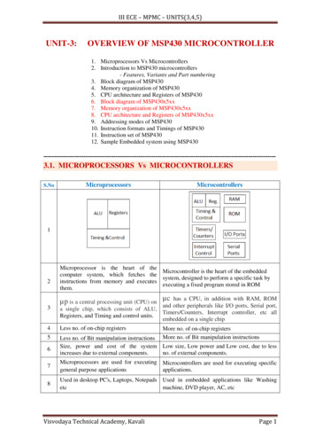
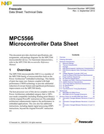
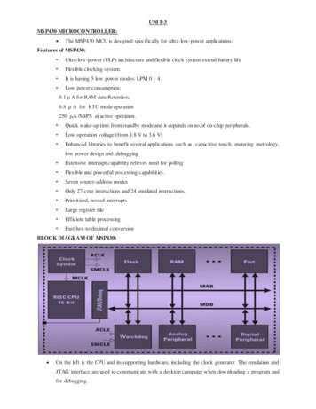
UNI T-3MSP430 MICROCONTROLLER: The MSP430 MCU is designed specifically for ultra-low-power applications.Features of MSP430: Ultra-low-power (ULP) architecture and flexible clock system extend battery life Flexible clocking system. It is having 5 low power modes: LPM 0 – 4. Low power consumption:0.1 μ A for RAM data Retention,0.8 μ A for RTC mode operation250 μA /MIPS at active operation. Quick wake-up time from standby mode and it depends on no.of on-chip peripherals. Low operation voltage (from 1.8 V to 3.6 V). Enhanced libraries to benefit several applications such as capacitive touch, metering metrology,low power design and debugging Extensive interrupt capability relieves need for polling Flexible and powerful processing capabilities. Seven source-address modes Only 27 core instructions and 24 emulated instructions. Prioritized, nested interrupts Large register file Efficient table processing Fast hex-to-decimal conversionBLOCK DIAGRAM OF MSP430: On the left is the CPU and its supporting hardware, including the clock generator. The emulation andJTAG interface are used to communicate with a desktop computer when downloading a program andfor debugging.
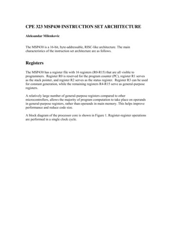
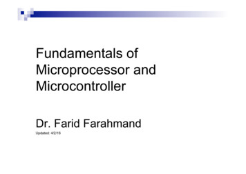
These MSP controller families share a 16-bit CPU core, RISC type, intelligent peripherals and flexibleclock system that interconnect using a 16-bit Von Neumann common memory address bus (MAB)and memory data bus (MDB) architecture. It is having no.of general purpose I/O ports, each of size 8-bit. All the pins can be configured either asinput or output to interface digital signal. This architecture is rich in on-chip analog and digital peripherals.Analog Peripherals: A/D Converters, Comparator, LCD Driver, Supply Voltage SupervisorDigital Peripherals: Watch-dog timer, 16-bit and 8-bit Timers, Hardware Multiplier, Universal SerialCommunication Interface (USCI) etc.,Clock Generator:The MSP430 addresses the conflicting demands for high performance, low power, and a precise frequency byusing three internal clocks, which can be derived from up to four sources. These are the internal clocks, whichare the same in all devices: Master clock, MCLK, is used by the CPU. Subsystem master clock, SMCLK, is distributed to peripherals. Auxiliary clock, ACLK, is also distributed to peripherals.Memory: These devices have flash memory, 2KB to 32KB and 128 bytes to 2KB of RAM. The size ofmemories varies from family to family.Central Processing Unit The CPU of MSP 430 includes a 16-bit ALU and a set of 16 Registers R0 –R15.In these registers Four arespecial Purpose and 12 are general purpose registers. The special Purpose Registers are PC (Program Counter), SP (Stack Pointer) , SR (Status Register)and CGx (Constant Generator)R0 (Program Counter (PC)):This contains the address of the next instruction to be executed—―points to‖ the instruction in the codememory.R1 (Stack Pointer (SP)):When a subroutine is called the CPU must jump to the subroutine, execute the code there, and finish byreturning to the instruction after the call. It must therefore keep track of the contents of the PC before jumpingto the subroutine so that it can return afterward. This is done with a stack, which is also known as a last in–firstout (LIFO) data structure.The stack is allocated at the top of RAM and grows down toward low addresses. The
stack pointer holds the address of the top of the stack. The operation of the stack is illustrated in below Figure.The word 0x1234 has been added or pushed on to the stack. The value of SP is first decreased by 2. A wordhas been removed, pulled or popped from the stack into the register R15 the stack pointer is increased by 2.R2 (Status Register (SR)):The C, Z, N, and V bits are affected by many of the operations performed by the ALU The carry bit C is set when an extra bit generated from the result of an arithmetic operation. The zero flag Z is set when the result of an operation is 0. A common application is to check whethertwo values are equal The negative flag N is made equal to the msb of the result, which indicates a negative number if thevalues are signed. The signed overflow flag V is set when the result of a signed operation has overflowed.Enable InterruptsSetting the general interrupt enable or GIE bit enables maskable interrupts. Clearing the bit disables allmaskable interrupts. There are also nonmaskable interrupts, which cannot be disabled with GIE.Control of Low-Power ModesThe CPUOFF, OSCOFF, SCG0, and SCG1 bits control the mode of operation of the MCU. All systems arefully operational when all bits are clear. Setting combinations of these bits puts the device into one of its lowpower modes (LPM0 – 4).R2 and R3 (Constant Generators – CG1 & CG2)Both R2 and R3 are used to provide the 6 most commonly used constants.mov.w #0000h,R5 --------- Clears R5 registeradd.w #0001h,R6 --------- Increments R6
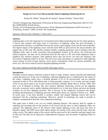
General instructions shown above wasteful of both memory and time because the values would have to befetched from memory whenever they were needed.To improve efficiency, if we use constant generators assource operands then the instructions look likemov.w R3,R5 --------- Clears R5 registeradd.w 0(R3),R6 --------- Increments R6 RegisterAddressing ModeRegisterIndexedRegister IndirectIndirect Auto-increment RegisterGeneral-Purpose RegistersR2 (CG1) 0000h0004h0008hR3 (CG2)0000h0001h0002hFFFFh (–1)The remaining 12 registers R4–R15 have no dedicated purpose and may be used as general working registers.ADDRESSING MODES OF MSP430:Addressing mode means the way of specifying the operands in an instruction. The MSP430 has sevenaddressing modes to interact with the CPU registers. The MSP430 supports seven addressing modes for thesource operand and four addressing modes for the destination operand. They are Register mode Indexed mode Symbolic mode Absolute mode Indirect register mode Indirect auto increment register mode Immediate mode1. Register ModeThis uses one or two of the registers in the CPU. It is the most straightforward addressing mode and isavailable for both source and destination.Ex: MOV.W R4, R5 - Move (copy) the contents of source (register R4) to destination (R5). The registersare specified in the instruction word; no further data are needed. It is also the fastest mode and this instructiontakes only 1 cycle. Any of the 16 registers can be used for either source or destination but there are somespecial cases:2. Indexed ModeThe Indexed mode commands are formatted as X(Rn), where X is a constant and Rn is one of the CPUregisters. The absolute memory location is addressed by adding a constant base address to the contents of aCPU register; the value in the register is not changed.Ex : MOV. B 3(R5), R4Move (copy) the contents at source address (3 R5) to destination (register R4)Indexed addressing can be used for the source, destination, or both.3. Symbolic ModeSymbolic mode allows the assignment of labels to fixed memory locations, so that those locations can beaddressed directly with the assigned label name. For example, suppose that a program uses the variable
LoopCtr, which occupies a word. The following instruction stores the value of LoopCtr in R6 using symbolicmode.Ex: mov.w LoopCtr ,R6 ; load word LoopCtr into R64. Absolute ModeIt is similar to Symbolic mode, with the difference that the label is preceded by ―&‖. The word following theinstruction contains the absolute address.Ex: mov.b &P1IN ,R6 ; load byte P1IN into R6Where PIN is the absolute address of the register. This addressing mode is used for special function andperipheral registers, whose addresses are fixed in the memory map. This addressing mode can be used for bothsource and destination operands.5. Register indirect modeThis is available only for the source operand and is shown by the symbol @ in front of a register, @Rn. Itmeans that the contents of Rn are used as the address of the operand. In other words, Rn holds a pointer ratherthan a value.Ex: mov.w @R5 ,R6 ; load word from address (R5) 4 into R66. Indirect Autoincrement Register ModeThis is also applicable only for the source operand and the format is specified with a symbol ‗@‘ infront of the register and sign after it, such as @Rn . Here, Rn register value is used as data pointer andincrements the register content after the operation by 1 (for byte operations) or 2 (for word operation).Ex: mov.w @R5 ,R6A word is loaded from address 4 into R6 and the value in R5 is incremented to 6 because a word (2bytes) was fetched.This mode cannot be used for the destination.7. Immediate ModeIn this addressing mode, the immediate data is specified as the operand in the instruction i.e., the datais readily available as a part instruction that will be fetched from the memory for the operation.Immediate mode is used to assign constant values to registers or memory locations. The immediate data cannotbe a destination operand.Ex: mov.w #0900h,R5INSTRUCTION SET OF MSP430:The MSP430 instruction set consists of 27 core instructions. Additionally, it supports 24 emulated instructions.The core instructions have unique op-codes decoded by the CPU, while the emulated ones need assemblers andcompilers to generate their mnemonics.The instruction set is orthogonal with few exceptions, meaning that alladdressing modes can be used with all instructions and registers. There are three formats of instruction.Double operand (Format I): Arithmetic and logical operations with two operands such as add.w src, dst.Both operands must be specified in the instruction.Single operand (Format II): A mixture of instructions for control or to manipulate a single operand, which iseffectively the source or destination for the addressing modes.
Jumps: The jump to the destination rather than its absolute address, in other words the offset that must beadded to the program counter.The ―return from interrupt‖ instruction reti is unique in requiring no operands.This would usually be described as inherent addressing but TI curiously classifies it as Format II without data.1. Movement instructionsThere is only the one ‗mov‘ instruction to move data. It can address all of memory as either source ordestination, including both registers in the CPU and the whole memory map. This is an excellent feature.mov.w src ,dst ; move (copy)dst srcStack OperationsThese push data onto the stack and pop them off using stack pointer. The SP is fixed to be even, so a word ofstack space is always consumed, even if only a byte is added.push.w src ; push data onto stack *--SP srcpop.w dst ; pop data off stack dst *SP -------------------------------- emulated2. Arithmetic and Logic Instructions with Two OperandsBinary Arithmetic Instructions with Two OperandsThese are fairly standard. The carry bit should be interpreted as ―not borrow‖ for subtraction:add.w src ,dst ; add dst srcaddc.w src ,dst ; add with carry dst (src C)adc. w dst ; add carry bit dst C --------------------------------------- emulatedsub.w src ,dst ; subtract dst – srcsubc.w src ,dst ; subtract with borrow dst – (src C)sbc.w dst ; subtract borrow bit dst – C--------------------------------- emulatedcmp.w src ,dst ; compare , set flags only (dst - src)The compare operation cmp is the same as subtraction sub except that only the bits in SR are affected; theresult is not written back to the destination.Arith metic Instru ctions with One OperandAll these are emulated, which means that the operand is always a destination:clr.w dst ; clear dst 0-----------------------------------emulateddec.w dst ; decrement dst – –---------------------------------emulateddecd. w dst ; double decrement dst - 2 ------------------------- emulatedinc.w dst ; increment dst --------------------------------- emulatedincd.w dst ; double increment dst 2 ------------------------emulatedtst.w dst ; test (compare with 0) (dst - 0) ----------------------- emulatedThe test operation is the special case of comparison with 0. In many processors the clear operation differs froma move with the value 0 because a move sets the flags but a clear does not. This does not apply to the MSP430because a move does not set the flags.Logic Instru ctions with Two OperandsThese are not quite the same as in many other processors:and. w s rc, ds t ; bitwis e anddst & srcxor . w s rc, dst ; bitwise e xc lus iv e ordst ˆ srcbit . w s rc, ds t ; bitwis e te s t, set f lags only ( dst & src)bis . w s rc, dst ; bit setdst srcbic . w s rc, ds t ; bit cleardst & srcThe MSP430 has the usual and and exclusive-OR xor instructions but not an explicit inclusive-OR. The andand bitwise test operations are identical except that bit is only a test and does not change its destination.
Logic Instru ctions with One OperandThere is only one of these, the invert invinstruction, also known as ones complement, which changes allbits of 0 to 1 and those of 1 to 0:inv . w ds t ; inv ert bitsdst dstemulatedIt is emulated using xorand inherits its peculiarity C Z. Its operand is a destination. It is not the same aschanging the sign of a number, which is the twos complement.Byte ManipulationThese instructions do not need a suffix because the size of the operands is fixed:s wpbSrc; swap upper and lower bytes ( word only )s xtSrc; extend sign of lower byte ( word only)Oper ations on Bits in Status RegisterThere is a set of emulated instructions to set or clear the four lowest bits in the status register, thosethat can be masked using the constant generator:Clrc; clear carry bitC 0e m ulate dClrn; clear ne gativ e bitN 0e m ulate dClrz; clear zero bitZ 0e m ulate dSe tc; set carr y bitC 1e m ulate dSe tn; set ne gativ e bitN 1e m ulate dSe tz; set zero bitZ 1e m ulate dDint; disable gene ral inter rupt sGI E 0e m ulate dEint; enable gener al inter ruptsGI E 1e m ulate d3. Shift and Rotate InstructionsLogical shift inserts zeroes for both right and left shifts.Arithmetic shift inserts zeroes for left shifts but the most significant bit, which carries the sign, isrepli
INSTRUCTION SET OF MSP430: The MSP430 instruction set consists of 27 core instructions. Additionally, it supports 24 emulated instructions. The core instructions have unique op-codes decoded by the CPU, while the emulated ones need assemblers and compilers to generate their mnemonics.The instruction set is orthogonal with few exceptions, meaning that all addressing modes can be used