Transcription
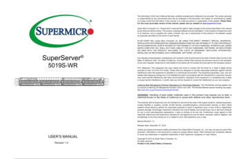
The information in this User’s Manual has been carefully reviewed and is believed to be accurate. The vendor assumesno responsibility for any inaccuracies that may be contained in this document, and makes no commitment to updateor to keep current the information in this manual, or to notify any person or organization of the updates. Please Note:For the most up-to-date version of this manual, please see our website at www.supermicro.com.Super Micro Computer, Inc. ("Supermicro") reserves the right to make changes to the product described in this manualat any time and without notice. This product, including software and documentation, is the property of Supermicro and/or its licensors, and is supplied only under a license. Any use or reproduction of this product is not allowed, exceptas expressly permitted by the terms of said license.SuperServer 5019S-WRIN NO EVENT WILL Super Micro Computer, Inc. BE LIABLE FOR DIRECT, INDIRECT, SPECIAL, INCIDENTAL,SPECULATIVE OR CONSEQUENTIAL DAMAGES ARISING FROM THE USE OR INABILITY TO USE THIS PRODUCTOR DOCUMENTATION, EVEN IF ADVISED OF THE POSSIBILITY OF SUCH DAMAGES. IN PARTICULAR, SUPERMICRO COMPUTER, INC. SHALL NOT HAVE LIABILITY FOR ANY HARDWARE, SOFTWARE, OR DATA STOREDOR USED WITH THE PRODUCT, INCLUDING THE COSTS OF REPAIRING, REPLACING, INTEGRATING,INSTALLING OR RECOVERING SUCH HARDWARE, SOFTWARE, OR DATA.Any disputes arising between manufacturer and customer shall be governed by the laws of Santa Clara County in theState of California, USA. The State of California, County of Santa Clara shall be the exclusive venue for the resolutionof any such disputes. Supermicro's total liability for all claims will not exceed the price paid for the hardware product.FCC Statement: This equipment has been tested and found to comply with the limits for a Class A digital devicepursuant to Part 15 of the FCC Rules. These limits are designed to provide reasonable protection against harmfulinterference when the equipment is operated in a commercial environment. This equipment generates, uses, and canradiate radio frequency energy and, if not installed and used in accordance with the manufacturer’s instruction manual,may cause harmful interference with radio communications. Operation of this equipment in a residential area is likelyto cause harmful interference, in which case you will be required to correct the interference at your own expense.California Best Management Practices Regulations for Perchlorate Materials: This Perchlorate warning applies onlyto products containing CR (Manganese Dioxide) Lithium coin cells. “Perchlorate Material-special handling may apply.See ING: Handling of lead solder materials used in this product may expose you to lead, achemical known to the State of California to cause birth defects and other reproductive harm.The products sold by Supermicro are not intended for and will not be used in life support systems, medical equipment,nuclear facilities or systems, aircraft, aircraft devices, aircraft/emergency communication devices or other criticalsystems whose failure to perform be reasonably expected to result in significant injury or loss of life or catastrophicproperty damage. Accordingly, Supermicro disclaims any and all liability, and should buyer use or sell such productsfor use in such ultra-hazardous applications, it does so entirely at its own risk. Furthermore, buyer agrees to fullyindemnify, defend and hold Supermicro harmless for and against any and all claims, demands, actions, litigation, andproceedings of any kind arising out of or related to such ultra-hazardous use or sale.Manual Revision 1.0Release Date: December 07, 2015USER’S MANUALRevision 1.0Unless you request and receive written permission from Super Micro Computer, Inc., you may not copy any part of thisdocument. Information in this document is subject to change without notice. Other products and companies referredto herein are trademarks or registered trademarks of their respective companies or mark holders.Copyright 2015 by Super Micro Computer, Inc.All rights reserved.Printed in the United States of America
SuperServer 5019S-WR User's ManualPrefacePrefaceContentsChapter 1 IntroductionAbout this Manual1.1 Overview.8This manual is written for professional system integrators and PC technicians. It providesinformation for the installation and use of the SuperServer 5019S-WR. Installation andmaintainance should be performed by experienced technicians only.Please refer to the 5019S-WR server specifications page on our website for updates onsupported memory, processors and operating systems (http://www.supermicro.com).1.2 Unpacking the System.81.3 System Features.91.4 Server Chassis Features.10Control Panel.10Front Features.11Rear Features.12Notes1.5 Motherboard Layout.13For your system to work properly, please follow the links below to download all necessarydrivers/utilities and the user’s manual for your server.Quick Reference Table.14Chapter 2 Server Installation Supermicro product manuals: http://www.supermicro.com/support/manuals/2.1 Overview.17 Product drivers and utilities: ftp://ftp.supermicro.com2.2 Preparing for Setup.17 Product safety info: http://www.supermicro.com/about/policies/safety information.cfmIf you have any questions, please contact our support team at:support@supermicro.comThis manual may be periodically updated without notice. Please check the Supermicro websitefor possible updates to the manual revision level.Choosing a Setup Location.17Rack Precautions.17Server Precautions.18Rack Mounting Considerations.18Ambient Operating Temperature.18Airflow.18Mechanical Loading.18WarningsCircuit Overloading.19Special attention should be given to the following symbols used in this manual.Reliable Ground.192.3 Installing the Rails.20Warning! Indicates important information given to prevent equipment/property damageor personal injury.Identifying the Sections of the Rack Rails.20Installing the Inner Rails.20Installing the Outer Rails.21Warning! Indicates high voltage may be encountered when performing a procedure.2.4 Installing the Server into a Rack.22Installing to a Standard Rack.22Installing to a Telco Rack.23Chapter 3 Maintenance and Component Installation3.1 Removing Power.243.2 Accessing the System.243.3 Motherboard Components.2534
SuperServer 5019S-WR User's ManualPrefaceProcessor and Heatsink Installation.25Chapter 6 BIOSMemory Installation.296.1 Introduction.56Memory Support.29Starting the Setup Utility.56PCI Expansion Card Installation.306.2 Main Setup.57Motherboard Battery.316.3 Advanced Setup Configurations.593.4 Chassis Components.326.4 Event Logs.83Front Bezel.326.5 IPMI. 85Hard Drives.326.6 Security.88Hard Drive Carrier Indicators.336.7 Boot.91DVD-ROM Drive Installation.346.8 Save & Exit.93System Cooling.34Appendix A BIOS Error CodesAppendix B Standardized Warning Statements for AC SystemsAppendix C System SpecificationsReplacing a Failed Fan.34Power Supply.36Power Supply Failure.36Chapter 4 Motherboard Connections4.1 Power Connections.384.2 Headers and Connectors.39Control Panel.43Data Cables.45Power Cables.454.3 Ports.46Rear I/O Ports.464.4 Jumpers.48Explanation of Jumpers.484.5 LED Indicators.51Chapter 5 Software5.1 OS Installation.52Installing the Windows OS for a RAID System.52Installing Windows to a Non-RAID System.525.2 Driver Installation.535.3 SuperDoctor 5.545.4 IPMI.5556
Contacting SupermicroHeadquartersAddress:Super Micro Computer, Inc.980 Rock Ave.San Jose, CA 95131 U.S.A.Tel: 1 (408) 503-8000Fax: 1 (408) 503-8008Email:marketing@supermicro.com (General Information)support@supermicro.com (Technical per Micro Computer B.V.Het Sterrenbeeld 28, 5215 ML's-Hertogenbosch, The NetherlandsTel: 31 (0) 73-6400390Fax: 31 (0) 73-6416525Email:sales@supermicro.nl (General Information)support@supermicro.nl (Technical Support)rma@supermicro.nl (Customer ss:Super Micro Computer, Inc.3F, No. 150, Jian 1st Rd.Zhonghe Dist., New Taipei City 235Taiwan (R.O.C)Tel: 886-(2) 8226-3990Fax: 886-(2) w.supermicro.com.tw7
SuperServer 5019S-WR User's ManualChapter 1: IntroductionChapter 11.3 System FeaturesThe following table provides you with an overview of the main features of the 5019S-WR.Please refer to Appendix C for additional specifications.Introduction1.1 OverviewSystem FeaturesThis chapter provides a brief outline of the functions and features of the 5019S-WR. The5019S-WR is based on the X11SSW-F motherboard and the SC815TQC-R504WB chassis.In addition to the motherboard and chassis, several important parts that are included withthe system are listed Intel Xeon E3-1200 v5 and 6th Gen Core i3, Pentium and CeleronMain Parts ListDescriptionPart NumberQuantitySocket TypePassive Heatsink for 1U SystemSNK-P0046P1LGA1151 (H4)4-cm Cooling FanFAN-0156L4 or FAN-0086L44BackplaneBPN-SAS3-815TQ-P1Hot-swap Hard Drive TraysMCP-220-00075-0B4Supports up to 64GB of unbuffered ECC DDR4-2133/1866/1600/1333 SDRAMAir ShroudMCP-310-19002-0N1Riser CardRSC-R1UW-E8R1ChipsetRiser CardRSC-W-681Rack Rail Mounting KitMCP-290-00054-0N1MemoryIntel C236 chipsetExpansion SlotsOne Proprietary WIO-R slot (using RSC-R1UW-E8R riser card)One Proprietary WIO-L slot (using RSC-W-68 riser card)One M.2 NGFF connector [supports PCIe 3.0 x4 (32 Gb/s)]1.2 Unpacking the SystemHard DrivesInspect the box the SuperServer 5019S-WR was shipped in and note if it was damaged inany way. If any equipment appears damaged, please file a damage claim with the carrierwho delivered it.Decide on a suitable location for the rack unit that will hold the server. It should be situatedin a clean, dust-free area that is well ventilated. Avoid areas where heat, electrical noise andelectromagnetic fields are generated. It will also require a grounded AC power outlet nearby.Be sure to read the precautions and considerations noted in Appendix B.Four 3.5" hot-swap hard drivesPowerRedundant 500W power (two power supply modules)Form Factor1U rackmountDimensions(WxHxD) 17 x 1.7 x 25.6 in. (432 x 43 x 650 mm)89
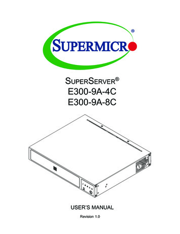
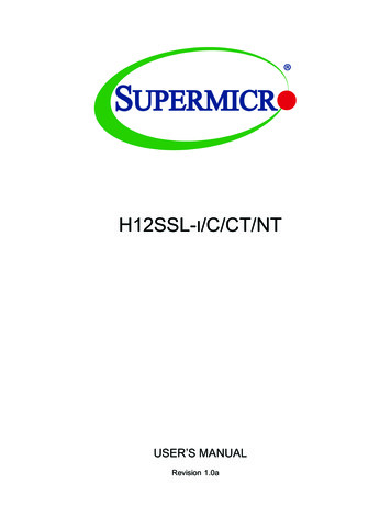
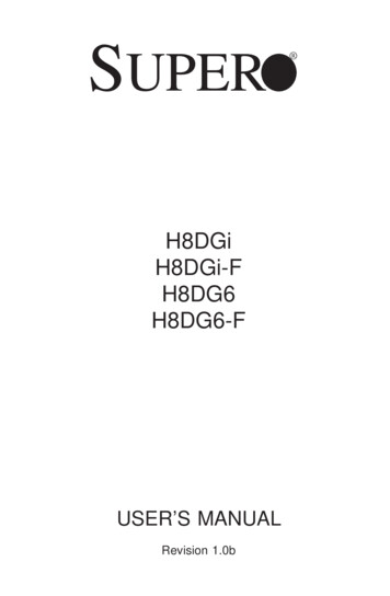
SuperServer 5019S-WR User's ManualChapter 1: Introduction1.4 Server Chassis FeaturesFront FeaturesThe SC815TQC-R504WB is a 1U chassis See the illustration below for the features includedon the front of the chassis.Control PanelThe switches and LEDs located on the control panel are described below. See Chapter 4 fordetails on the control panel connections.321123456784111Figure 1-2. Chassis Front ViewFigure 1-1. Control Panel ViewControl Panel FeaturesItemFeatureDescription1UID ButtonDepressing the UID (unit identifier) button illuminates an LED on both the frontand rear of the chassis for easy system location in large stack configurations.The LED will remain on until the button is pushed a second time.2Universal Information LEDSe table below for details.3NIC2 LEDIndicates network activity on LAN port 2 when flashing4NIC1 LEDIndicates network activity on LAN port 1 when flashing5HDD LEDIndicates activity on a hard drive when flashing.6Power LEDIndicates power is being supplied to the system power supply. This LED shouldnormally be illuminated when the system is operating.7Reset ButtonThe reset button is used to reboot the systemPower ButtonThe main power button is used to apply or remove power from the power supplyto the server. Turning off system power with this button removes the main powerbut maintains standby power. To perform many maintenance tasks, you mustalso unplug system before servicing8Front Chassis FeaturesItemFeatureDescription1Hard Drive CarrierCarrier for hot-swap hard drive2DVD ROM Drive(Optional) Slim DVD-ROM drive3Control PanelFront control panel with LEDs and buttons (see preceding page)4Rack Ear BracketsSecures server chassis to the rackInformation LEDStatusDescriptionContinuously on and redAn overheat condition has occured.(This may be caused by cable congestion.)Blinking red (1Hz)Fan failure, check for an inoperative fan.Solid blueLocal UID has been activated. Use this function tolocate the server in a rackmount environment.Blinking blueRemote UID is on. Use this function to identify theserver from a remote location.10114
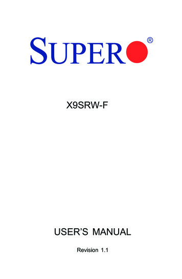
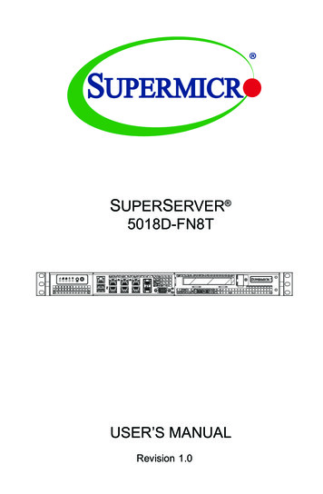
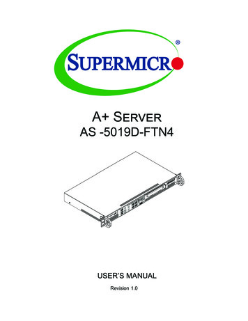
SuperServer 5019S-WR User's ManualChapter 1: Introduction1.5 Motherboard LayoutRear FeaturesThe illustration below shows the features included on the rear of the chassis.Below is a layout of the X11SSW-F with jumper, connector and LED locations shown. Seethe table on the following page for descriptions. For detailed descriptions, pinout informationand jumper settings, refer to Chapter 4.USB6/7(3.0)USB0/1JI2C1IPMI LANSP14JPL1BMCLEDEC1JBT1Rear I/O ports (see Section 4.3)3Expansion Card SlotSlot for three expansion cards (requires pre-installed riser cards)2260X11SSW-FSRW3REV:1.01Designed in the USASecures server chassis to the rack2280JSXB1CRack Ear BracketsSRW2USB9/10(3.0)I/O Back PanelIntel PCHUSB4/52I-SATA4500W Platinum Level Power Supply (p/n PWS-504P-1R)I-SATA6Power .0)J23JSXB1BFeatureBT1LEDBMCRear Chassis FeaturesItemUSB2/3SRW4JSXB2Figure 1-3. Chassis Rear E21JSXB1A1LE1JUIDB1JBR13SRW1BIOSLICENSEJSD1 MI CODEJF1MAC CODEBAR CODEFAN6FAN5FAN4FAN3FAN2Figure 1-4. Motherboard Layout12JPWR213FAN1
SuperServer 5019S-WR User's ManualChapter 1: IntroductionQuick Reference TableJumperDescriptionDefault SettingJBR1BIOS RecoveryPins 1-2 (Normal)JBT1Clear CMOSSee Chapter 4JI2C1/JI2C2SMB to PCI Slots Enable/DisablePins 2-3 (Disabled)JPB1BMC Enable/DisablePins 1-2 (Enabled)JPG1VGA Enable/DisablePins 1-2 (Enabled)JPL1/JPL2LAN1/LAN2 Enable/DisablePins 1-2 (Enabled)JPME2Manufacturing Mode SelectPins 1-2 (Normal)JWD1Watch DogPins 1-2 (Reset)LEDDescriptionStatusLE1Rear UID LEDBlue: Unit IdentifiedLEDBMCBMC Heartbeat LEDBlinking Green: BMC NormalLEDEC1EC Heartbeat LEDBlinking Green: EC NormalLEDPWRSystem Standby Power LEDGreen: Power OnConnectorDescriptionBT1Onboard BatteryCOM1/COM2COM1/COM2 Port HeadersFan1-Fan6System/CPU Fan HeadersIPMI LANIPMI Dedicated Gigabit (RJ45) PortI-SATA2-I-SATA7SATA 3.0 Connectors via Intel PCH (6Gb/s)I-SGPIO 1/2Serial Link General Purpose I/O Connection Headers for I-SATA 3.0 Ports (I-SGPIO1 forI-SATA2-3, I-SGPIO2 for I-SATA4-7)J23M.2 Socket 3 (supports 2260, 2280, 22110 for NVMe and SATA SSDs)JD1Speaker/Power LED IndicatorJF1Front Panel Control HeaderJIPMB14-pin External BMC I2C Header (for an IPMI Card)JL1Chassis Intrusion HeaderJOH1Overheat LED IndicatorJPI2C1Power I2C System Management Bus (Power SMB) HeaderJPWR124-pin ATX Main Power ConnectorJPWR2 12V 8-pin CPU Power ConnectorJSD1/JSD2SATA Disk On Module (DOM) Power ConnectorsJSTBY1Standby Power HeaderJSXB1A/1B/1CSupermicro Proprietary WIO L (Left) Add-On Card SlotJSXB2Supermicro Proprietary WIO R (Right) Add-On Card SlotJTPM1Trusted Platform Module (TPM)/Port 80 ConnectorJUIDB1UID (Unit Identification) SwitchLAN1/LAN2Gigabit (RJ45) LAN Ports14ConnectorDescriptionSP1Internal Speaker/BuzzerUSB 0/1Back Panel USB 2.0 PortsUSB 2/3, USB 4/5Front Accessible USB 2.0 HeadersUSB 6/7Back Panel USB 3.0 PortsUSB 8USB 3.0 Type-A HeaderUSB 9/10Front Accessible USB 3.0 HeaderVGABack Panel VGA Port15
SuperServer 5019S-WR User's ManualFigure 1-5. C236 Chipset: System Block DiagramIMVP 8 80W3 PHASE for Vcore1 PHASE for VSAPCIe 3.0 x16PCI-E X16 8.0 1DMI3DMI3 x4#5/6/7/8#5#4#3#2#1#0#16.0 Gb/SRGRMIIPCHRMII/NCSIPHY#5#4#3#2#1USB 3.0RTL8211F-CGPCI-E X1 2.5 Gb/SDDR3SPIBMC Boot FlashBMCAST2400USB 2.0#13#5#4#3#2#1#14 USB2.0SPIUSB 2.0LPCVGA CONNCOM1Connector#6SPITPM HEADERDebug CardCOM2HeaderMUXSPISYSTEM POWERTemp SensorM.2 SSDPCI-E X1 2.5 Gb/S#2-#7RJ45PCI-E X4 8.0 Gb/SSATALAN 1i210RJ45#9/10/11/12#2SXB2USBRJ45PCI-E X1 2.5 Gb/SPCIe3.0 x4 (in x8)USBLAN 2i210PCI-E X4 8.0 Gb/SFRONT PANELFAN SPEEDCTRLBIOSNote: This is a general block diagram and may not exactly represent the features on yourmotherboard. See the System Specifications appendix for the actual specifications of yourmotherboard.16
Chapter 2: Server InstallationChapter 2Server Installation2.1 OverviewThis chapter provides advice and instructions for mounting your system in a server rack.If your system is not already fully integrated with processors, system memory etc., refer toChapter 4 for details on installing those specific components.Caution: Electrostatic Discharge (ESD) can damage electronic components. To prevent suchdamage to PCBs (printed circuit boards), it is important to use a grounded wrist strap, handleall PCBs by their edges and keep them in anti-static bags when not in use.2.2 Preparing for SetupThe box in which the system was shipped should include the rackmount hardware needed toinstall it into the rack. Please read this section in its entirety before you begin the installation.Choosing a Setup Location The system should be situated in a clean, dust-free area that is well ventilated. Avoid areaswhere heat, electrical noise and electromagnetic fields are generated. Leave enough clearance in front of the rack so that you can open the front door completely( 25 inches) and approximately 30 inches of clearance in the back of the rack to allowsufficient space for airflow and access when servicing. This product should be installed only in a Restricted Access Location (dedicated equipmentrooms, service closets, etc.). This product is not suitable for use with visual display workplace devices acccording to §2of the the German Ordinance for Work with Visual Display Units.Rack Precautions Ensure that the leveling jacks on the bottom of the rack are extended to the floor so thatthe full weight of the rack rests on them.17
SuperServer 5019S-WR User's Manual Chapter 2: Server InstallationIn single rack installations, stabilizers should be attached to the rack. In multiple rack installations, the racks should be coupled together. Always make sure the rack is stable before extending a server or other component fromthe rack. You should extend only one server or component at a time - extending two or more simultaneously may cause the rack to become unstable.Server Precautions Review the electrical and general safety precautions in Appendix B. Determine the placement of each component in the rack before you install the rails. Install the heaviest server components at the bottom of the rack first and then work yourway up. Use a regulating uninterruptible power supply (UPS) to protect the server from powersurges and voltage spikes and to keep your system operating in case of a power failure. Allow any drives and power supply modules to cool before touching them. When not servicing, always keep the front door of the rack and all covers/panels on theservers closed to maintain proper cooling.Rack Mounting ConsiderationsCircuit OverloadingConsideration should be given to the connection of the equipment to the power supply circuitryand the effect that any possible overloading of circuits might have on overcurrent protectionand power supply wiring. Appropriate consideration of equipment nameplate ratings shouldbe used when addressing this concern.Reliable GroundA reliable ground must be maintained at all times. To ensure this, the rack itself should begrounded. Particular attention should be given to power supply connections other than thedirect connections to the branch circuit (i.e. the use of power strips, etc.).To prevent bodily injury when mounting or servicing this unit in a rack, you must takespecial precautions to ensure that the system remains stable. The following guidelinesare provided to ensure your safety: This unit should be mounted at the bottom of the rack if it is the only unit in the rack. When mounting this unit in a partially filled rack, load the rack from the bottom to the topwith the heaviest component at the bottom of the rack. If the rack is provided with stabilizing devices, install the stabilizers before mounting orservicing the unit in the rack.Ambient Operating TemperatureIf installed in a closed or multi-unit rack assembly, the ambient operating temperature ofthe rack environment may be greater than the room's ambient temperature. Therefore,consideration should be given to installing the equipment in an environment compatible withthe manufacturer’s maximum rated ambient temperature (TMRA).AirflowEquipment should be mounted into a rack so that the amount of airflow required for safeoperation is not compromised.Mechanical LoadingEquipment should be mounted into a rack so that a hazardous condition does not arise dueto uneven mechanical loading.1819
SuperServer 5019S-WR User's ManualChapter 2: Server Installation2.3 Installing the RailsInstalling the Outer RailsThere are a variety of rack units on the market, which may require a slightly different assemblyprocedure.The following is a basic guideline for installing the system into a rack with the rack mountinghardware provided. You should also refer to the installation instructions that came with thespecific rack you are using.Identifying the Sections of the Rack RailsYou should have received two rack rail assemblies in the rack mounting kit. Each assemblyconsists of two sections: an inner fixed chassis rail that secures directly to the server chassisand an outer fixed rack rail that secures directly to the rack itself (see Figure 2-1). Two pairsof short brackets to be used on the front side of the outer rails are also included.Begin by measuring the distance from the front rail to the rear rail of the rack. Attach a shortbracket to the front side of the right outer rail and a long bracket to the rear side of the rightouter rail. Adjust both the short and long brackets to the proper distance so that the rail canfit snugly into the rack. Secure the short bracket to the front side of the outer rail with twoscrews and the long bracket to the rear side of the outer rail with three screws. Repeat thesesteps for the left outer rail.Locking Tabs: Both chassis rails have a locking tab, which serves two functions. The firstis to lock the server into place when installed and pushed fully into the rack, which is itsnormal position. Secondly, these tabs also lock the server in place when fully extended fromthe rack. This prevents the server from coming completely out of the rack when you pull itout for servicing.Installing the Inner RailsBoth the left and right side inner rails have been pre
1 Power Supply 500W Platinum Level Power Supply (p/n PWS-504P-1R) 2 I/O Back Panel Rear I/O ports (see Section 4.3) 3 Expansion Card Slot Slot for three expansion cards (requires pre-installed riser cards) 4 Rack Ear Brackets Secures server chassis to the rack Figure 1-3. Chassis Rear View Rear Features