Transcription
OneWirelessXYR 6000 Pressure TransmitterR120 User's Manual34-XY-25-15Revision 8November 2010
Notices and TrademarksCopyright 2008-10 by Honeywell International Inc.Revision 8 November 2010While this information is presented in good faith and believed to be accurate, Honeywell disclaims the impliedwarranties of merchantability and fitness for a particular purpose and makes no express warranties except as maybe stated in its written agreement with and for its customers.In no event is Honeywell liable to anyone for any indirect, special or consequential damages. The information andspecifications in this document are subject to change without notice.Honeywell, PlantScape, Experion PKS, and TotalPlant are registered trademarks of Honeywell International Inc.Other brand or product names are trademarks of their respective owners.Honeywell Process Solutions1860 West Rose Garden LanePhoenix, Arizona 85027iiOneWireless XYR 6000 Pressure Transmitter R120 User's ManualRevision 8November 2010
About This DocumentThis document describes preparation, operation and maintenance of the XYR 6000 Wireless Pressure Transmitters.Mounting, installation and wiring are covered in other documents.Honeywell does not recommend using devices for critical control where there is a single point of failure or wheresingle points of failure result in unsafe conditions. OneWireless is targeted at open loop control, supervisorycontrol, and controls that do not have environmental or safety consequences. As with any process control solution,the end-user must weigh the risks and benefits to determine if the products used are the right match for theapplication based on security, safety, and performance. Additionally, it is up to the end-user to ensure that thecontrol strategy sheds to a safe operating condition if any crucial segment of the control solution fails.Revision InformationDocument NameDocument IDXYR 6000 Pressure Transmitter R120 User's Manual34-XY-25-1510KPSI and IS battery holderRevisionNumberPublication Date8November 2010ReferencesThe following list identifies all documents that may be sources of reference for material discussed in this publication.Document TitleXYR 6000 Transmitters Quick Start GuideGetting Started with Honeywell OneWireless SolutionsOneWireless Wireless Builder User’s GuideOneWireless Builder Parameter ReferenceRevision 8November 2010OneWireless XYR 6000 Pressure Transmitter R120 User's Manualiii
Support and contact infoUnited States and CanadaContact:Honeywell Process Solution Global Technical Support - Phone: 001-800-423-9883 Customer Service (HFS) - Phone: 001-800-343-0228 Outside United States - Phone: 001-215-641-3610Calls are answered by dispatcher between 6:00 am and 4:00 pm Mountain StandardTime. Emergency calls outside normal working hours are received by an answeringservice and returned within one hour.Email support: ask-ssc@honeywell.comMail:Honeywell Process Solutions1860 West Rose Garden Lane,Phoenix, AZ, 85027EuropeContact:Phone:Facsimile:Mail:Honeywell TAC-EMEA 32-2-728-2732 32-2-728-2696TAC-BE02Hermes PlazaHermeslaan, 1HB-1831 Diegem, BelgiumContact:Phone:Honeywell Global TAC – Pacific1300-300-4822 (toll free within Australia) 61-8-9362-9559 (outside Australia) 61-8-9362-9564Honeywell Limited Australia5 Kitchener WayBurswood 6100, Western well Global TAC – India 91-20- 6603-9400 91-20- 6603-9800Honeywell Automation India Ltd.56 and 57, Hadapsar Industrial EstateHadapsar, Pune –411 013, one:Facsimile:Mail:Email:ivHoneywell Global TAC – Korea 82-2-799-6317 82-11-9227-6324 82-2-792-9015Honeywell Co., Ltd17F, Kikje Center B/D,191, Hangangro-2GaYongsan-gu, Seoul, 140-702, KoreaGlobal-TAC-Korea@honeywell.comOneWireless XYR 6000 Pressure Transmitter R120 User's ManualRevision 8November 2010
People’s Republic of ChinaContact:Honeywell Global TAC – ChinaPhone: 86- 21-5257-4568Mail:Honeywell (China) Co., Ltd33/F, Tower A, City Center, 100 Zunyi Rd.Shanghai 200051, People’s Republic of Contact:Phone:Facsimile:Mail:Email:Honeywell Global TAC – South East Asia 65-6580-3500 65-6580-3501 65-6445-3033Honeywell Private LimitedHoneywell Building17, Changi Business Park Central 1Singapore csimile:Mail:Email:Honeywell Global TAC – Taiwan 886- 7- 536-2567 886-7-536-2039Honeywell Taiwan Ltd.17F-1, No. 260, Jhongshan 2nd Road.Cianjhen DistrictKaohsiung, Taiwan, ne:Facsimile:Mail:Email:Honeywell Global TAC – Japan 81-3-6730-7160 81-3-6730-7228Honeywell Japan Inc.New Pier Takeshiba, South Tower Building,20th Floor, 1-16-1 Kaigan, Minato-ku,Tokyo 105-0022, JapanGlobal-TAC-JapanJA25@honeywell.comWorld Wide WebHoneywell Solution Support l your nearest Honeywell office.Training ClassesHoneywell Automation College:http://www.automationcollege.comRevision 8November 2010OneWireless XYR 6000 Pressure Transmitter R120 User's Manualv
Symbol DefinitionsThe following table lists those symbols used in this document to denote certain conditions.SymbolDefinitionATTENTION: Identifies information that requires special consideration.TIP: Identifies advice or hints for the user, often in terms of performing a task.CAUTIONIndicates a situation which, if not avoided, may result in equipment or work (data) onthe system being damaged or lost, or may result in the inability to properly operatethe process.CAUTION: Indicates a potentially hazardous situation which, if not avoided, mayresult in minor or moderate injury. It may also be used to alert against unsafepractices.CAUTION symbol on the equipment refers the user to the product manual foradditional information. The symbol appears next to required information in themanual.WARNING: Indicates a potentially hazardous situation, which, if not avoided, couldresult in serious injury or death.WARNING symbol on the equipment refers the user to the product manual foradditional information. The symbol appears next to required information in themanual.WARNING, Risk of electrical shock: Potential shock hazard where HAZARDOUSLIVE voltages greater than 30 Vrms, 42.4 Vpeak, or 60 VDC may be accessible.ESD HAZARD: Danger of an electro-static discharge to which equipment may besensitive. Observe precautions for handling electrostatic sensitive devices.Protective Earth (PE) terminal: Provided for connection of the protective earth(green or green/yellow) supply system conductor.Functional earth terminal: Used for non-safety purposes such as noise immunityimprovement. NOTE: This connection shall be bonded to Protective Earth at thesource of supply in accordance with national local electrical code requirements.Earth Ground: Functional earth connection. NOTE: This connection shall bebonded to Protective Earth at the source of supply in accordance with national andlocal electrical code requirements.Chassis Ground: Identifies a connection to the chassis or frame of the equipmentshall be bonded to Protective Earth at the source of supply in accordance withnational and local electrical code requirements.continuedviOneWireless XYR 6000 Pressure Transmitter R120 User's ManualRevision 8November 2010
SymbolDescription The Factory Mutual Approval mark means the equipment hasbeen rigorously tested and certified to be reliable.The Canadian Standards mark means the equipment has beentested and meets applicable standards for safety and/orperformance.The Ex mark means the equipment complies with the requirementsof the European standards that are harmonized with the 94/9/ECDirective (ATEX Directive, named after the French "ATmosphereEXplosible").For radio equipment used in the European Union in accordancewith the R&TTE Directive the CE Mark and the notified body (NB)identification number is used when the NB is involved in theconformity assessment procedure. The alert sign must be usedwhen a restriction on use (output power limit by a country at certainfrequencies) applies to the equipment and must follow the CEmarking.The C-Tick mark is a certification trade mark registered to ACMA(Australian Communications and Media Authority) in Australia underthe Trade Marks Act 1995 and to RSM in New Zealand undersection 47 of the NZ Trade Marks Act. The mark is only to be usedin accordance with conditions laid down by ACMA and RSM. Thismark is equal to the CE Mark used in the European Union.N314 directly under the logo is Honeywell’s unique supplieridentification number.Revision 8November 2010OneWireless XYR 6000 Pressure Transmitter R120 User's Manualvii
viiiOneWireless XYR 6000 Pressure Transmitter R120 User's ManualRevision 8November 2010
ContentsSupport and contact info.iv1.INTRODUCTION . 11.1Purpose .11.2Scope.11.3OneWireless network overview .11.4About the transmitter.12.SPECIFICATIONS . 32.1European Union Usage.32.2Certifications and approvals.4Transmitter .4Provisioning Device .52.3Agency compliance information.5FCC compliance statements .5IC compliance statements .5Radio Frequency (RF) statement .6European Union restriction .6Japanese Restrictions .62.4Honeywell European (CE) Declaration of Conformity (DoC) .7For more information about the R&TTE Directive.92.5IECEx Conditions of Certification.9ATEX Conditions for Safe Use .93.PREPARATION . 103.1Installation .103.2Configuration.103.3Connecting to network .103.4Calibrating the transmitter .10Overview .10Calibrate zero .104.FUNCTION BLOCKS. 124.1Introduction .124.2Block description .12Block types .12Block diagram.124.3Parameter details .13Revision 8November 2010OneWireless XYR 6000 Pressure Transmitter R120 User's Manualix
Contents5.OPERATION . 145.1Overview .14Display modes . 14Authentication Device . 145.2Transmitter connection status.155.3Transmitter PV display .165.4Transmitter quick view of parameters .205.5Transmitter menu .21Menu tree. 215.6Authentication device menus .22Overview . 22Main menu . 22Security and Node Deployment . 23Device Local Configuration . 25Read Node Information . 26Advanced Options. 286.MAINTENANCE/REPAIR . 296.1Introduction .296.2Preventive maintenance .296.3Inspecting and cleaning barrier diaphragms .29Tools required . 29Procedure . 30Torque ratings . 316.4Replacing sensor module .32Tools required . 32Procedure . 326.5Replacing batteries .34When to replace. 34Tools required . 34Procedure . 346.6Replacing 24V external power module .36When to replace. 36Tools required . 36Procedure . 366.7Replacing antenna .39Tools required . 39Procedure . 396.8Parts .42Transmitter body . 42Meter body . 436.9xDimension drawings .48OneWireless XYR 6000 Pressure Transmitter R120 User's ManualRevision 8November 2010
ContentsTablesTablesTable 1 Calibrate zero .11Table 2 Transmitter connection status .15Table 3 PV engineering units .16Table 4 PV status .17Table 5 Device status .17Table 6 Menu tree.21Table 7 Buttons for Device Local Configuration .25Table 8 Advanced Options .28Table 9 Inspecting and Cleaning Barrier Diaphragms.30Table 10 Process Head Bolt Torque Ratings .31Table 11 Sensor module replacement.32Table 12: IS Battery Pack replacement procedure.35Table 13 24V External power module .38Table 14 Antenna replacement procedure .40Table 15 Parts (see Figure 13, Figure 14).44Table 16 Parts .47Table 17 Drawing numbers for DP models STDW924, STDW930, STDW974 .48Table 18 Drawing numbers for DHGP models STGW944, STGW974 .48Table 19 Drawing numbers for GP/AP models STGW94L, STGW97L, STGW98L, STAW94L, STGW99L.48Revision 8November 2010OneWireless XYR 6000 Pressure Transmitter R120 User's Manualxi
ContentsFiguresFiguresFigure 1 XYR 6000 Functional Diagram .2Figure 2 Block Diagram .12Figure 3 Main menu.22Figure 4 Security and Node Deployment.23Figure 5 Device Local Configuration screen.25Figure 6 Read Node Information .26Figure 7 Advanced Options .28Figure 8 Assembly of DP Transmitter Process Heads .31Figure 9 Sensor module removal and replacement .33Figure 10: IS Battery Pack.35Figure 11 24V Power Supply Module Assembly .37Figure 12 Antenna replacement .41Figure 13 STDW924, STDW930, STDW974.43Figure 14 STGW944, STGW974 .43Figure 15 GP/AP models STGW94L, STGW97L, STGW98L, STGW99L, STAW94L.47xiiOneWireless XYR 6000 Pressure Transmitter R120 User's ManualRevision 8November 2010
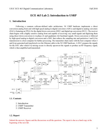
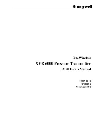
1. Introduction1.1. Purpose1. Introduction1.1PurposeThis manual describes the Honeywell OneWireless XYR 6000 Pressure Transmitter function, operationand maintenance.1.2ScopeThe manual includes:1.3 Details of topics that relate uniquely to the Honeywell XYR 6000 Pressure Transmitter, This manual does not cover installation, mounting, or wiring. See XYR 6000 Transmitter Quick StartGuide (document 34-XY-25-21).OneWireless network overviewOneWireless is an all digital, serial, two-way communication mesh network that interconnects industrialfield sensors to a central system.OneWireless has defined standards to which field devices and operator stations communicate with oneanother. The communications protocol is built as an "open system" to allow all field devices andequipment that are built to OneWireless standard to be integrated into a system, regardless of the devicemanufacturer. This interoperability of devices using OneWireless technology is to become an industrystandard for automation systems.1.4About the transmitterThe XYR 6000 Pressure Transmitter is furnished with OneWireless interface to operate in a compatibledistributed OneWireless system. The transmitter will interoperate with any OneWireless-registered device.The transmitter includes OneWireless electronics for operating in a 2.4GHz network. It features functionblock architecture.The XYR 6000 Pressure Transmitter comes in a variety of models for measurement applications involvingone of these basic types of pressure: Differential pressure, Gauge pressure, Absolute pressure.The transmitter measures the process pressure and transmits the measured value as a digital output signalin user-configured engineering units. Its major components are electronics housing and a meter body asshown in Figure 1 (a typical differential pressure model transmitter).The XYR 6000 transmits its output in a digital OneWireless protocol format for direct digitalcommunications with systems.The Process Variable (PV) is available for monitoring and alarm purposes. Available PV update rates: 1, 5,10, 30 seconds and are set on Wireless Builder. Slower update rates extend battery life. The meter bodytemperature is also available as a secondary variable for monitoring. Figure 1 shows a block diagram ofthe XYR 6000 Pressure transmitter’s operating functions.Revision 8November 2010OneWireless XYR 6000 Pressure Transmitter R120 User's Manual1
1. Introduction1.4. About the nDataMeasurementBoardDP or adioBoardAntennaBatteryMeter BodyElectronics HousingConfigurationDataFigure 1 XYR 6000 Functional Diagram2OneWireless XYR 6000 Pressure Transmitter R120 User's ManualRevision 8November 2010
2. Specifications2.1. European Union Usage2. Specifications2.1European Union UsageThis product may be used in any of the following European Union nations.ISO 3166ISO 3166CountryCountry2 letter code2 letter riaBGLithuaniaLTCyprusCYMaltaMTCzech andISSwedenSEIrelandIESwitzerlandCHItalyITUnited KingdomBGRevision 8November 2010OneWireless XYR 6000 Pressure Transmitter R120 User's Manual3
2. Specifications2.2. Certifications and approvals2.2Certifications and approvalsTransmitterRefer to product label for applicable ratings.Approval / ItemRatings / DescriptionCSAcus IntrinsicallySafeCL I, Div 1, Groups A, B, C, & D; CL II, Div 1, Groups E, F & G; CL III, T4CSAcus ExplosionproofCL I, Div 1, Groups A, B, C, & D; CL II, Div 1, Groups E, F & G; CL III, T4CL I, Zone 0: Ex ia IIC, T4; CL I, Zone 0: AEx ia IIC, T4CL I, Zone 1: Ex d IIC, T4; CL I, Zone 1: AEx d IIC, T4CSAcus NonincendiveCL I, Div 2, Groups A, B, C & D; CL II, Div 2, Groups F & G; CL III, Div 2, T4CL I, Zone 2: Ex nA IIC, T4; CL I, Zone 2: AEx nA IIC, T4FM ApprovalsCL I, Div 1, Groups A, B, C, & D; CL II, Div 1, Groups E, F & G; CL III, T4Intrinsically SafeCL I, Zone 0: AEx ia IIC, T4FM ApprovalsCL I, Div 1, Groups A, B, C, & D; CL II, Div 1, Groups E, F & G; CL III, T4ExplosionproofCL I, Zone 1: AEx d IIC, T4FM ApprovalsCL I, Div 2, Groups A, B, C & D; CL II, Div 2, Groups F & G; CL III, Div 2, T4NonincendiveCL I, Zone 2: AEx nA IIC, T4HON – ATEX, Ex nA IIC, T4; Ta 85 C, Zone 2Non-SparkingKEMA 08 ATEX0062XEx ia IIB; T4 Ta 70ºC; Ex tD A20 IP66 T90ºCIntrinsically SafeEx d [ia] IIB; T4 Ta 70ºC; Ex tD A21 IP66 T90ºCFlameproofNon-SparkingEx nA [nL] IIC; T4 Ta 84ºC; Ex tD A22 IP66 T90ºCIECEx CSA 09.0001XIntrinsically SafeFlameproofEx ia IIB; T4 Ta 70ºC; DIP A20
Mail: Honeywell Limited Australia 5 Kitchener Way Burswood 6100, Western Australia Email: GTAC@honeywell.com India Contact: Honeywell Global TAC - India Phone: 91-20- 6603-9400 Facsimile: 91-20- 6603-9800 Mail: Honeywell Automation India Ltd. 56 and 57, Hadapsar Industrial Estate Hadapsar, Pune -411 013, India