Transcription
WHITEPAPERIntroduction To The Two-Wire Transmitter And The4-20mA Current Loop IT V -I-R Bulletin # 8500-904-A10L000877-214-6267 sales@acromag.com www.acromag.com 30765 Wixom Rd, Wixom, MI 48393 USA
INTRODUCTION TO THE TWO-WIRE TRANSMITTER ANDTHE 4-20MA CURRENT LOOPBackground3The Basics of 4-20mA Current Loops3Power Supply:4Receiver:5Transmitter:6Wire:7Popular Wired Applications8What makes 4-20mA signal transmission so attractive?9The Future of 4-20mA10About Acromag10877-214-6267 sales@acromag.com www.acromag.com2 30765 Wixom Rd, Wixom, MI 48393 USA
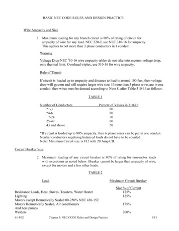
INTRODUCTION TO THE TWO-WIRE TRANSMITTER ANDTHE 4-20MA CURRENT LOOPBackgroundFirst appearing in the 1950’s with the advent of electrical and electronic controls, the 4-20mA signal standard reigns as one of the most popular mediumsfor signal transmission and electronic control in industrial environments nearly 60 years later.Prior to the widespread adoption of electrical and electronic controls, buildings often used pneumatic control systems. Large and powerful compressorsdrove 3psi to 15psi pneumatic signals throughout a plant and these pneumatic lines connected to pneumatically controlled valves and pneumaticallycontrolling valves in order to drive proportional controls and actuators throughout the building, all powered from compressed air. Air pressure at 3psiserved as the “live-zero” and 15psi represented 100%. In this way, the more modern 4-20mA signal standard emulated the earlier 3-15psi pneumaticcontrols. Any pressure below 3psi was considered “dead zero” and an alarm condition. Some installations still use pneumatic control today. Modern I/Pconverters (current-to-pressure transducers) are available to convert the 4-20mA control loops to common pneumatic ranges, such as 3-15psi, 1-18psi,3-27psi, and 6-30psi.In two-wire 4-20mA control loops, we use 2-wire transmitters to convert various process signals representing flow, speed, position, level, temperature,pressure, strain, pH, etc., to 4-20mA DC for the purpose of transmitting the signal over some distance with little or no loss of signal. This paper reviews theoperation of this transmission standard and its advantages, in particular as it relates to two-wire transmitters and the associated 4-20mA current loop.The Basics of 4-20mA Current LoopsTo help understand new concepts, I like to simplify them with easy to remember relationships. For the two-wire 4-20mA current loop, I use a simpletriangle as follows: TIRFigure 1: Symbolic 2-Wire Current LoopFrom the triangle, I can quickly identify the three common components of a current loop, how they are wired together, and even the direction of currentflow. For my mental model, each side of the triangle represents a component of the current loop. The vertices of the triangle represent a wired connectionbetween these components. For reference, I also place a positive/plus sign on the “peak” of the triangle. I will also use the first three letters of “TRIangle”to identify the principle components. Accepting the convention that current flow will move from the supply positive to and return to the supply negative, Isee that current moves counter-clockwise in my symbolic current loop.877-214-6267 sales@acromag.com www.acromag.com3 30765 Wixom Rd, Wixom, MI 48393 USA
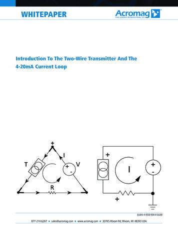
INTRODUCTION TO THE TWO-WIRE TRANSMITTER ANDTHE 4-20MA CURRENT LOOP IT IV - RFigure 2A: 2-Wire Current LoopWith Component SUbstitutionsFigure 2B: Traditional 2-WireCurrent Loop w/ Earth GroundThe left side is labeled “T” and refers to “Transmitter”. The base of the triangle is labeled “R” and refers to “Receiver”. The right side of the triangleis labeled “I” and refers to the source of current or the power supply. The vertices refer to the wired connections between these elements. Eachelement shares two connections to the loop. The “ ” label at the peak shows that the positive side of the power supply connects to the positiveside of the transmitter. Using the convention of current flow from positive to negative, the direction of current flow from the power supply is showncounter-clockwise.You should also note that the Transmitter is not the source of current, but simply regulates the flow and magnitude of the current through it. The currentis sourced by the power supply, flows in controlled fashion through the transmitter, then into the receiver, and returns to the power supply. The currentflowing through the receiver produces a voltage that is easily measured by the analog input of a controller or monitoring device. Figure 2B shows aschematic of a simple 4-20mA current loop. Note the traditional position of earth ground in the current loop of Figure 2B.To help us to understand the operation of a two-wire current loop, let’s consider each element of the current loop separately:1. Power Supply: The current loop uses DC power because the magnitude of the current represents the signal level that is being transmitted. If ACpower was instead used in the loop, the magnitude of current would be continuously changing, making it difficult to discern the signal level beingtransmitted. For 4-20mA current loops with 2-wire transmitters, the most common loop power supply voltage is 24V DC, but there are also instancesof 12V, 15V, and 36V DC. Some older systems use higher voltages. But the most important thing to remember about the power supply is that it mustbe set to a level that is greater than the sum of the minimum voltage required to operate the Transmitter, plus the IR drop in the Receiver, and for longtransmission distances, the IR drop in the wire. Calculating this drop must also consider the maximum level of current that can flow in the 4-20mAcurrent loop—not 20mA, but the over-scale or alarm limit of the transmitter.A common problem encountered in some installations, is that the loop receiver device will exhibit a roll-off in the measured signal at the top end of therange. This is usually due to a power supply voltage that can no longer drive the necessary loop voltage due to an added load in the current loop. Inmost cases, this can be related to a failure to account for the IR voltage drop in the wires when transmitting over long distances, or simply failing toinclude the over-range current in your calculation. It also occurs by adding too many receivers, or loads to the loop.Tel 248-295-0880 Fax 248-624-9234 sales@acromag.com 4www.acromag.com 30765 Wixom Rd, Wixom, MI 48393 USA
INTRODUCTION TO THE TWO-WIRE TRANSMITTER ANDTHE 4-20MA CURRENT LOOPNote that this paper focuses mainly on 2-wire “Type 2” transmitters, which must use DC power supplies (see Figure 3A below). However, the ANSI/ISAstandard 50.00.01 actually describes three different current loop connection types. The two-wire transmitter described here is a Type 2 connection type,in which the transmitter has a “floating” connection relative to ground. The standard also describes a Type 3 connection type, or 3-wire transmitterloop, where the Transmitter and Receiver share a ground connection with power, and the transmitter uses a third wire to connect to power outside ofthe current loop. Type 4 refers to a 4-wire transmitter where the Transmitter and Receiver float, and separate power leads power the transmitter outsideof the current loop. Four-wire transmitters can be AC or DC powered. In fact, 24VAC is a common power voltage for AC powered 4-wire transmitters.The following figures show the three basic transmitter connection types:Note that in most installations, the power supply is local to either the transmitter, or the receiver. Some receiver devices will include an excitation sourceat their input, typically 24VDC. These are typically referred to as “sourcing inputs”, referring to their double-duty as both a loop receiver, and a sourceof current for the loop.2. Receiver: This is the device at the other end of the transmission line that “receives” the transmitted signal. In a 4-20mA process loop, the Receivercould be located thousands of feet from the transmitter. Because it is much easier to measure voltage than current, we often use a resistor to representthe Receiver in a 2-wire current loop. This resistor can be a physical resistor, or simply the input impedance of the receiver channel. The Receiver itselfcould be any number of different devices, such as: a panel meter, actuator valve, motor speed control, a PLC (Programmable Logic Controller), or otherDCS (Digital Control System). It may even be another transmitter, signal isolator, or even a wireless transducer. But for most Receiver devices, the loopcurrent is commonly passed through a resistor to produce a voltage for measurement by the device. Thus, the simplest receiver can be represented by aload resistance connected in parallel with a voltmeter.The voltage generated across the internal resistance of the Receiver is the signal which the Receiver processes. An analog current loop can be convertedto a voltage input with a precision resistor. Further, by using 4-20mA as the driver, the voltage produced across a load resistor is easily scaled by simplychanging the resistance. Common resistances used are 250Ω (1-5V), 500Ω (2-10V), 50Ω (0.2-1V), and 100Ω (0.4-2V). Note also that you are notlimited to a single receiver in any given current loop, but could choose to connect several receiving devices in series in the loop with each receiverdriven by the same current. But always keep in mind that the loop power supply must be sufficient to drive the voltage produced across the load ofthe receiver at maximum current, plus the voltage drop in the wiring, and all the while maintaining the minimum voltage required by the transmitter tomaintain operation.Depending on the source of current for the loop, receiver devices may be classified as active (supplying power), or passive (relying on loop power). Forexample, a chart recorder may additionally provide loop power to a pressure transmitter. Panel mount displays and chart recorders are receivers that arecommonly referred to as “indicator devices” or ‘process monitors’.Although the two-wire current loop is less sensitive to induced noise, it’s not immune to noise pickup, particularly over long transmission distances. Inthese applications, it is helpful to place a 0.1uF capacitor directly across the Receiver input. This helps to filter out high frequency noise and is especiallyimportant for wide-band or high-speed receiver inputs. For 60Hz AC noise, additional “bulk” filtering of 1uF or greater may also be required.Tel 248-295-0880 Fax 248-624-9234 sales@acromag.com 5www.acromag.com 30765 Wixom Rd, Wixom, MI 48393 USA
INTRODUCTION TO THE TWO-WIRE TRANSMITTER ANDTHE 4-20MA CURRENT LOOP3. Transmitter: This is the device used to transmit data from a sensor over the two-wire current loop. There can be only one Transmitter output in anycurrent loop. It acts like a variable resistor with respect to its input signal and is the key to the 4-20mA signal transmission system. The transmitterconverts the real world signal, such as flow, speed, position, level, temperature, humidity, pressure, etc., into the control signal necessary to regulatethe flow of current in the current loop. The level of loop current is adjusted by the transmitter to be proportional to the actual sensor input signal. Animportant distinction is that the transmitted signal is not the current in the loop, but rather the sensor signal it represents. The transmitter typically uses4mA output to represent the calibrated zero input or 0%, and 20mA output to represent a calibrated full-scale input signal or 100% as shown in Figure4 below:The relationship between the output current value and process variable measurement is set by calibration of the transmitter, which assigns a differentrange of engineering units to the span between 4 and 20 mA. In some transmitters, the mapping between the sensor engineering units and outputcurrent can even be inverted, such that 4mA represents the full-scale process variable, and 20mA the minimum process signal.Since the focus of this paper is on the 4-20mA, 2-wire current loop, an important distinction of the 2-wire transmitter used in these loops is that theyactually draw their operating power from the current flowing through them and the voltage across them. Because the lowest level of the transmissionsignal is 4mA or less (essentially a “live zero” signal), the transmitter must be able to operate from less than 4mA. Two-wire transmitters will also haveminimum and maximum output voltage ratings that must be observed. The lower voltage is the minimum voltage required to operate the transmitter,and the maximum transmitter voltage is the highest voltage it can withstand.This is another benefit of loop-powered 2-wire transmitters: that they have their power supply and signal sharing the same pair of connection wires. Thissimplifies installation considerably, and the low DC transmission levels permit the use of small, inexpensive copper wiring.A common misconception about Transmitters is that they source the loop current, but the transmitter is not the source of the current. Rather, it is aseries connected current-sinking circuit that will attempt to draw current from a power supply wired to its output terminals. The current in the loop isthe medium via which the sensor signal is transmitted. The current flowing through the transmitter is proportional to the input signal being measured.When calibrated properly, this current will vary from 4 to 20mA over the range of its sensor input signal. The transmitter will also make allowances tosupport under-range and over-range output current levels.Another important point about the transmitter is that the voltage at its output terminals will vary according to the loop power supply voltage, the IRvoltage drop in the wires, and the IR voltage drop across the receiver. So you must make sure that the loop supply voltage level can drive the minimumrequired by the transmitter, plus the voltage drop in the wires, plus the voltage drop produced at the receiver for the maximum current level of the loop.The transmitter output voltage will adjust itself to dissipate any excess voltage in the loop, but the loop supply must never exceed the maximum voltagerating of the transmitter output.Tel 248-295-0880 Fax 248-624-9234 sales@acromag.com 6www.acromag.com 30765 Wixom Rd, Wixom, MI 48393 USA
INTRODUCTION TO THE TWO-WIRE TRANSMITTER ANDTHE 4-20MA CURRENT LOOP4. Wire: Referring back to our triangular depiction of the two-wire current loop, the vertices of the triangle represent the connections between theelements, or the wire used to wire the elements together. The impact of the wire resistance in the current loop is often ignored, as it usually contributesnegligible IR voltage drop over short distances and small installations. However, over long transmission distances, this drop can be significant and mustbe accounted for, as some current loop installations will use wire distributed over hundreds and even thousands of feet. To illustrate the impact of wireresistance, the following table lists the resistance of common copper wire gauges.Table 1: Bare Copper Wire REsistance at 25 C (77 F)Wire AWGDIAMETER (mils)OHMS Per 1000 6.30266365.00423383.97673403.141070As an example of the potential impact wire resistance can haveon an installation, let’s assume that we have wired our loopelements together using 3000 feet of 24 AWG, plenum-rated,instrumentation and control wire. Note that 3000 feet is the totalround-trip length of wire. Thus, we can calculate a wire resistance of3000ft*26.2Ω/1000ft 78.6Ω. This will result in a voltage drop of0.022A* 78.6Ω 1.73V at a maximum loop current of 22mA.If you find yourself having to do these kinds of calculations often, but you do not have an AWG Copper Wire Chart handy, you can approximate the wireresistance of a given gauge by committing three points to memory: 40 AWG copper wire is approximately 1Ω per foot (refer to Table 1 and see 40AWG is 1070Ω per 1000 feet, or 1.07Ω per foot). Every 10 wire gauges lower divides resistance by 10 (refer to Table 1 and note that 30AWG is 105.2Ω per 1000 feet, or 0.1Ω per foot). Every 3 wire gauges lower halves the resistance.For example, to approximate the resistance of 24AWG copper wire, without having to refer to a table, you can do the math in your head as follows:Remembering that 40AWG is 1Ω/foot. Then 10AWG lower is 30AWG and one-tenth of this, or 0.1Ω/foot. Then 3 AWG lower is 27AWG at one halfof this, or 0.05Ω/foot. Then 3 AWG lower at 24AWG is one half of that, or 0.025Ω/foot. Now check this against Table 1 and note that 24AWG wire isactually 26.17Ω per 1000 feet, or 0.02617Ω per foot. Our approximation is less than 5% from the value in Table 1. You will note slight differences inwire resistance values from manufacturer to manufacturer.877-214-6267 sales@acromag.com www.acromag.com7 30765 Wixom Rd, Wixom, MI 48393 USA
INTRODUCTION TO THE TWO-WIRE TRANSMITTER ANDTHE 4-20MA CURRENT LOOPYou must always make sure the loop supply voltage is always large enough to drive the minimum transmitter voltage Vt, plus the IR voltage drop in thewire, plus the IR voltage drop in the receiver, and at maximum loop current. In Figure 5 below, the simplified current loop has been modified to accountfor this wire resistance by depicting this resistance as a single series-connected resistor Rw in the loop. Note that when referring to the length of thecable, which in many installations is shielded twisted pair, you must account for the resistance of both wires combined, or the resistance of the “roundtrip” length of the two-wire loop.From another perspective, if my power supply is 24V minimum, the transmitter requires 8V, my maximum current is 22mA, and 1.73V is dropped in thewire (0.022A*78.6Ω), what is the maximum receiver load that I can support? To answer this, simply use Ohms law to calculate Rr Vr/I (Vs-Vt-Vw)/I (24V-8V-1.73V)/0.022A 648Ω. Note that 648Ω represents the total resistance that can be driven at 22mA and if you have multiple receivers, thisresistance is split between the devices and this sum cannot exceed 648Ω.Popular Wired ApplicationsThe floating connection relative to ground makes two-wire “Transmitters” somewhat flexible in the way they connect to various “Receiver” devices. Inmost installations, the loop power supply will be local to either the transmitter, or local to the remote receiver. Shielded twisted pair wiring is often usedto connect the longest distance between the field transmitter and remote receiver. The receiver device is commonly the input channel of a ProgrammableLogic Controller (PLC), a Digital Control System (DCS), or a panel meter. Some receivers already provide excitation for the transmitter and these are referredto as “sourcing” inputs. Other receivers that do not provide excitation are referred to as “sinking” inputs and these will require that a separate powersupply connect in the loop. Here are example transmitter connection diagrams for “sourcing” and “sinking” receiver types:877-214-6267 sales@acromag.com www.acromag.com8 30765 Wixom Rd, Wixom, MI 48393 USA
INTRODUCTION TO THE TWO-WIRE TRANSMITTER ANDTHE 4-20MA CURRENT LOOPSome installations will use a single power supply to drive multiple currentloops, as shown in Figure 7 at left. In this example, the power supplymust be rated for at least three times the maximum transmitter current.However, a short circuit or other high-current fault in any loop couldproduce a power failure that would disable all transmitters powered by thesource. These applications will usually implement some form of currentlimiting and/or fault protection. For example, intrinsically safe loops includea barrier device that limits the current and voltage to a transmitter. Faultprotected sources add another level of system safety. Setting a current limiton each loop lets you size the power supply without over-specifying it.What makes 4-20mA signal transmission so attractive?While we’ve reviewed some of the fundamentals of 4-20mA two-wire current loops and the basic loop elements, and we have an idea of how they worktogether, let’s consider some of the advantages of 4-20mA signal transmission.Probably the greatest advantage of using a current loop for signal transmission is the current loop’s low sensitivity to electrical noise. This is very importantfor long distance transmission in harsh industrial environments. As a generally low impedance system, it is much less sensitive to induced noise, thanperhaps the high impedance input of a voltage amplifier. The currents injected by typical noise sources are generally no more than a few hundred microamps, usually insignificant to the 16mA span. The use of a “Live Zero” also improves the signal to noise ratio at low levels, allowing us to accuratelydiscern low signal levels without added noise or interference.Another advantage to the 4-20mA current loop is that it is essentially lossless with respect to the transmission media (wire) and the interconnections(connectors). That is, the accuracy of the signal is not affected by the voltage drop in the interconnecting wiring. This allows the signal transmission tooccur over long distances, with varying conductors. Compare this to voltage signals, which will always have an associated signal loss related to the lengthof the wires—the 4-20mA signal current does not exhibit any signal losses under this same scenario. Kirchoff’s Current Law teaches us that the current ina loop is equivalent at any point in the loop. That is, if you happen to be reading 12mA at your receiver input, you can be certain that 12mA is passingthrough your transmitter.The 4mA “Zero-Offset”, “Live Zero”, or “Positive-Zero” is Failsafe. The use of 4mA as the starting point for our transmitted signal is useful in troubleshooting, as signal integrity is verified with 0% of input and output signal. A failed current loop due to a lead break or open device can be immediatelydiscerned as zero current flow, which is a fail-safe level outside of the signal range. By offsetting the signal from zero, some transmitters will define analarm limit just below 4mA and different from zero, allowing a receiver to detect other failures in the system, like an input sensor lead break. Having a livezero in your control system also allows you to set the “zero” of your controlled device (i.e. an actuator valve or other device) just a little bit below 4mA tohold it completely OFF. You wouldn’t be able to do that with a zero-based 0-20mA output. A “Live Zero” of 4mA also permits the two-wire current loopto power the transmitter, simplifying installation and reducing costs.The 4-20mA current loop also allows additional “Receiver” devices to be connected in series in the loop without a loss of signal. That is, as long as theloop voltage supply has sufficient capacity to drive the additional IR voltage drops of the added devices, and its voltage does not exceed the maximumvoltage rating of the transmitter. For example, you might choose to wire a panel meter, a trend recorder, and a PLC input card in series in the same currentloop. The loop transmitter will maintain proper current in the loop, up to the voltage capability of the loop. The number of additional receiver devices youcan add is only limited by the available voltage level.The 4-20mA transmission standard also has low inherent energy, minimizing its ability to couple noise into other systems and also reducing its radiatedemissions. Contrast that to the older pneumatic systems that use inefficient high power compressors up to 50HP to drive compressed air through theircontrol lines.877-214-6267 sales@acromag.com www.acromag.com9 30765 Wixom Rd, Wixom, MI 48393 USA
INTRODUCTION TO THE TWO-WIRE TRANSMITTER ANDTHE 4-20MA CURRENT LOOPThe Future of 4-20mALooking ahead, the future continues to look bright for the 4-20mA signal transmission standard in industrial environments. Its lossless nature, lowersensitivity to induced noise, its live-zero offset, fail-safe operation, and easy scalability contribute to its longevity. Plus its adaptability to many different wireconductors and connectors, and its relative immunity to poor quality connections, all contribute to its popularity. And because it is so widely supported bythousands of compatible devices, including wireless transducers, it would be difficult to unseat it as the leading analog transmission standard for industrialI/O. Likewise, modern variations of 4-20mA such as HART1 continue to drive support for the standard.HART refers to Highway Addressable Remote Transducer, and is a digital communication standard that superimposes a 0.5mA digital signal at high frequency on the 4-20mA process signalto facilitate digital communication between HART enabled devices, that include controllers, computers, smart sensors, and actuators. This protocol uses Bell 202 Frequency Shift Keying at thephysical layer with a “1” represented by 1200Hz, and a “0” by 2400Hz. In this way HART enabled devices allow the transmission of communication parameters, in addition to and simultaneouswith, the normal analog process signal output. All HART enabled devices must store 35 to 40 data items and parameters as a standard feature, and these parameters include device status,diagnostic alerts, process variables and units, loop current and percentage range, basic configuration parameters, and manufacturer and device tag (ID) information.1About AcromagAcromag’s new DT Series Signal Conditioners are designed to offer a cost-effective space-saving solution to interface a variety of process and sensor signalsto your control systems. Each model supports several input ranges and can output a proportional 0/4-20mA, 0-10V, or /-10V DC signals.Acromag is a multi-million-dollar international corporation that combines more than 60 years of process monitoring and control experience with a solidbackground in high-tech computer design.We are focused on developing industrial I/O solutions that provide the best long-term value in the industry. A complete line of industrial I/O productsincluding process instruments, signal conditioning equipment, data acquisition boards, distributed I/O modules, and network communication devices areavailable. Industries served include manufacturing, water services, power generation, mining, defense, and transportation.Acromag I/O is ideal for a broad range of monitoring and control operations where controllers communicate with instrumentation on the plant floor or inthe field.877-214-6267 sales@acromag.com www.acromag.com10 30765 Wixom Rd, Wixom, MI 48393 USA
Tel 248-295-0880 Fax 248-624-9234 sales@acromag.com www.acromag.com 30765 Wixom Rd, Wixom, MI 48393 USA INTRODUCTION TO THE TWO-WIRE TRANSMITTER AND THE 4-20MA CURRENT LOOP 6 3. Transmitter: This is the device used to transmit data from a sensor over the two-wire current loop. There can be only one Transmitter output in any