Transcription
Ceiling CassetteIndoor Air HandlerInstallation ManualModels:BM12MCCBM18MCCIMPORTANT NOTE:Read this manual carefully beforeinstalling or operating your new airconditioning unit. Make sure to save thismanual for future reference.This manual only describes the outdoorunit of user’s. When using the indoor unit,refer to the user’s manual of indoor unit.
Table of Contents1. Safety Precautions. 02Warnings. 04Cautions. 052. Installation Summary. 063. Accessories . 074. Indoor Unit Installation . 095. Refrigerant Piping Installation . 126. Connecting the Drain Pipe . 147. Electrical Wiring Work . 168. Decorative Panel Installation . 17
Safety Precautions1Read Before UsingIncorrect usage may cause serious damage or injury.The seriousness of potential damage or injuries is classified as either a WARNING or CAUTION.WARNINGCAUTIONThis symbol indicates that ignoring instructions may cause death orserious injury.This symbol indicates that ignoring instructions may cause moderateinjury to your person, or damage to your unit or other property.This symbol indicates that you must never perform the action indicated.WARNING Installation must be performed in accordance with the requirement of NEC and CEC byauthorized personnel only. Be sure only trained and qualified service personnel install, repair or service the equipment. Improper installation, repair, and maintenance may result in electric shocks, short-circuit,leaks, personal injury, loss of life, fire or other damage to the equipment. Install according to this installation instructions strictly. If installation is defective, it will causewater leakage, electrical shock and fire. When installing the unit in a small room, take measures against to keep refrigerantconcentration from exceeding allowable safety limits in the event of refrigerant leakage.Contact the place of purchase for more information. Excessive refrigerant in a closedambient can lead to oxygen deficiency. Use the attached accessories parts and specified parts for installation. Otherwise, it will causethe unit to fall, leak water, cause electrical shock, or produce fire. Install at a strong and firm location which is able to withstand the unit's weight. If thestrength is not enough or installation is not properly done, the set will drop causing injury. The appliance must be installed 8' above floor. The appliance shall not be installed in the laundry room. Before obtaining access to terminals, all supply circuits must be disconnected. Read this manual thoroughly before starting up the units. For electrical work, follow all local and national wiring codes and these installationinstructions. An independent circuit and electrical disconnect must be used. If electricalcircuit capacity is not enough or defect in electrical work, it will cause electrical shock or fire. Use the specified cable and connect tightly and clamp the cable so that no external force willbe acted on the terminal. If connection or fixing is not perfect, it can cause malfunction or fireat the connection. Page 4 Revised 5/14/2020
WARNING Wiring routing must be properly arranged so that control board cover is fixed properly.If control board cover is not fixed perfectly, it can cause heat-up at connection point ofterminal, fire or electrical shock. If the supply cord is damaged, it must be replaced by the manufacture or its service agent ora similarly qualified person in order to avoid a hazard. An electrical disconnect switch having a contact separation of at least 0.12in in all polesshould be connected in fixed wiring. When carrying out piping connection, take care to not let air substances go into refrigerationcycle. Otherwise, it can cause lower capacity, abnormally high pressure in the refrigerationcycle, explosion and injury. Do not share the single circuit with other electrical appliances. Otherwise, it can cause poorperformance, fire or electrical shock. If the refrigerant leaks during installation, ventilate the area immediately. Toxic gas may beproduced if the refrigerant comes in contact with fire. The temperature of refrigerant circuit will be high, please keep the interconnection cableaway from the copper tube. After completing the installation work, check that the refrigerant does not leak. Toxic gas maybe produced if the refrigerant leaks into the room and comes into contact with a source offire, such as a fan heater, stove or cooker. After completing the installation, make sure that the unit operates properly during the startup operation.CAUTION Ground the air conditioner. Be sure to install an earth leakage breaker. Failure to install an earth leakage breaker may resultin electric shocks. Connect the outdoor unit wires, then connect the indoor unit wires. DO NOT connect the ground wire to gas or water pipes, lightning rod or a telephone groundwire. Inappropriate grounding may result in electric shocks. DO NOT connect the air conditioner with the power supply until the wiring and piping is done. DO NOT operate your air conditioner in a wet room such as a bathroom or laundry room. DO NOT install the air conditioner in the following circumstance: There are combustible gases present. There is salty air surrounding (near the coast). There is caustic gas (the sulfide, for example) existing in the air (near a hot spring). There is excessive vibration, as in a shop or factory. In small, hot industrial space such as a server room or commercial kitchen. In kitchen where it is full of oil gas. There is strong electromagnetic waves existing. There are inflammable materials or gas. There is acid or alkaline liquid evaporating. Other special conditions.Revised 5/14/2020 Page 5
InstallationSummary2Installation SummaryInstallation information To install properly, please read this "installation manual" at first. The air conditioner must be installed by qualified persons. When installing the indoor unit or its tubing, please follow this manual as strictly as possible. If the air conditioner is installed on a metal part of the building, it must be electrically insulatedaccording to the relevant standards to electrical appliances. When all the installation work is finished, please turn on the power only after a thorough check. Regret for no further announcement if there is any change of this manual caused by productimprovement.Installation order1. Indoor unit installation2. Outdoor unit installation3. Install the refrigerant pipe4. Connect the drain pipeCheck off when completedIs the indoor unit fixed firmly?The unit may drop, vibrate or make noise.Is the gas leak test finished?It may result in insufficient cooling or heating.5. Electric wiring workIs the unit fully insulated?Condensate water may drip.6. Installation of the decoration panelDoes drainage flow smoothly?Condensate water may drip.7. Test operationDoes the power supply voltage correspond to that shown onthe name plate?The unit may malfunction or components may burn out.Are wiring and piping correct?The unit may malfunction or components may burn out.Is the unit safely grounded?Dangerous at electric leakage.Is the wiring size in accordance with specifications?The unit may malfunction or components may burn out.Is anything blocking the air outlet or inlet of either the indooror outdoor units?It may result in insufficient cooling or heating.Are refrigerant piping length and additional refrigerantcharge noted down?The refrigerant charge in the system might not be clear. Page 6 Revised 5/14/2020
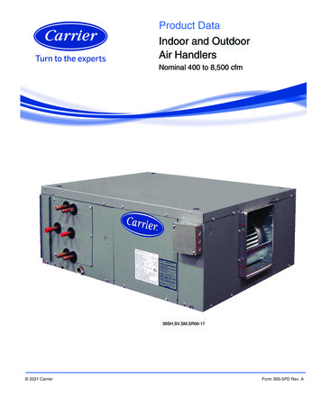
3AccessoriesNameShapeQuantityRemote control1Batteries2Tapping screws(M3X10mm)(on some models)2Metal champ(on some models)1Fixing screw for remotecontrol holderST2.9 x 102Remote control holder1OptionalPartsDrain hose(on some models)1Expansible hooks(on some models)4Installation hooks(on some models)4Throttle(on some models)1Anti-shock rubber(on some models)1Revised 5/14/2020 Page 7 AccessoriesThe air conditioning system includes the following accessories. Use all of the installation parts andaccessories to install the air conditioner. Improper installation may result in water leakage, electricalshock, fire, or equipment failure.
AccessoriesNameShapeQuantityDrain plug(only heat pump models)(with the outdoor unit)1Seal ring(only heat pump models)(with the outdoor unit)1Owner’s Manual1Installation Manual1Paper pattern forinstallation (on somemodels)1This indoor unit requires installation of an optional decoration panel.NOTE: All the pictures in this manual are for explanation purpose only. There may be slightlydifferent from the air conditioner you purchased ( depend on model ). The actual shape may vary. Page 8 Revised 5/14/2020
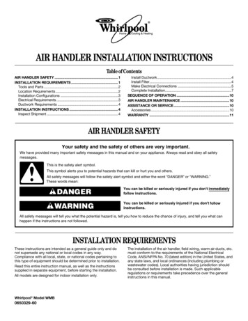
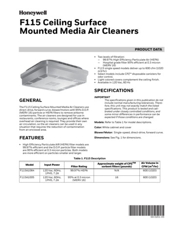
4Indoor Unit Installation39.4in21 Where nothing blocks air passage.39.4in Where optimum air distribution can be ensured.39.4in2Indoor UnitInstallation1. Select an installation site where the followingconditions are fulfilled and that meets yourcustomer's approval.98.4in10.2inWhen the conditions in the ceiling are exceeding86 F and a relative humidity of 80%, or whenfresh air is inducted into the ceiling, an additionalinsulation is required (minimum 0.4in / thickness,polyethylene foam).11.4inSelecting Installation Site39.4in Where condensate water can be properlydrained. Where the ceiling is level, not noticeably on anincline. Where sufficient clearance for maintenance andservice can be ensured. Where there is no risk of flammable gas leaking. Where piping between indoor and outdoor unitsdoes not exceed the allowable limit. (Refer tothe installation manual of the outdoor unit.) Keep indoor unit, outdoor unit, inter unit wiringand remote control wiring at least 3 feet awayfrom televisions and radios. This is to preventimage interference and noise in those electricalappliances. (Noise may be generated dependingon the conditions under which the electric waveis generated, even if proper distance is kept.) When installing the wireless remote control kit,the distance between wireless remote controland indoor unit might be shorter if there arefluorescent lights that are electrically started inthe room. The indoor unit must be installed asfar away as possible from fluorescent lights.2. Ceiling heightInstall this unit where the height of bottom panel ismore than 8' so that the user cannot easily touch.Revised 5/14/202039.4in39.4in The equipment is not intended for use in apotentially explosive atmosphere.12Air inletAir outletFig 4.13. Use Threaded Rod for InstallationUse threaded rod for installation. Check whetherthe ceiling is strong enough to support the weightof the indoor unit. If there is a risk, reinforce theceiling before installing the unit. Space required forinstallation. See Fig. 4.4 on the next page for details.WARNINGDo not install the unit in an area whereflammable materials are present due to risk ofexplosion resulting in serious injury or death.If the basis underneath the unit is not strongenough to support the weight of the unit,the unit could be fall out of place and causeserious injury. Page 9
1 20.6in1. Relation of ceiling opening to unit andsuspension bolt position.Adjust the position to ensure the gaps betweenthe indoor unit and the four sides of false ceilingare even. The indoor unit's lower part should sinkinto the false ceiling for 0.9in. See Fig. 4.3.2. Create the ceiling opening needed forindoor installation where applicable. (Forexisting ceilings.) C reate the ceiling opening required forinstallation. From the side of the opening tothe casing outlet, implement the refrigerantand drain piping and wiring for remotecontrol (unnecessary for wireless type). Referto each piping or wiring section. A fter making an opening in the ceiling, it maybe necessary to reinforce ceiling beams tokeep the ceiling level and to prevent it fromvibrating. Consult the builder for details.1 21.5in2 22.4in3 25.5in72.8in0.6in Page 10 80.6in0.8inFig 4.212Fig 4.3 U se expansible hooks, sunken anchors orother field supplied parts to reinforce theceiling in order to bear the weight of the unit. A djust clearance from the ceiling beforeproceeding further. See Fig. 4.4 forInstallation example.For other installation other than standardinstallation, contact your dealer for details.23.6in0.8in3. Install the threaded rod. (Use either a M8 orM10 size rod.)NOTE: The opening in the ceiling should notbe larger than the decorative grill, otherwiseadditional ceiling patching will be required.60.9inIndoor UnitInstallation1. Installation hook pitch dimensions2. Indoor unit dimensions3. Decoration panel dimensions4. Refrigerant piping5. Installation hook6. Ceiling opening dimensions7. Hanger bracket8. False ceiling2 22.4in3 25.5in54Preparations before installation1 Indoor unit2 False ceiling11.2 1.4in2341234Ceiling slabExpansible hook (optional)Installation hook (optional)False ceilingFig 4.4Revised 5/14/2020
Install the indoor unitWhen installing optional accessories, readalso the installation manual of the optionalaccessories. Depending on the field conditions,it may be easier to install optional accessoriesbefore the indoor unit is installed (except for thedecoration panel). However, for existing ceiling,install fresh air inlet component kit and branchduct before installing the unit.1. Install the indoor unit.2. Securing the hanger bracket see figurebelow.(Refer to the chapter "Preparations beforeinstallation").3. Check if the unit is horizontally leveled. D o not install the unit tilted. The indoor unitis equipped with a built-in drain pump andfloat switch. (If the unit is tilted against thedirection of the condensate flow (the drainpiping side is raised), the float switch maymalfunction and cause water to drip.) C heck to ensure the unit is level at all fourcorners.Indoor UnitInstallation1. Attach the hanger bracket to the threadedrod. Be sure to fix it securely by using a nutand washer from the upper and lower sidesof the hanger bracket.2. Adjust the unit to the right position forinstallation.Nut (field supply)HangerbracketWasher(field supply)Double nuts(field supply,tighten)Fig 4.5Revised 5/14/2020 Page 11
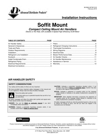
5Refrigerant Piping InstallationWARNINGAll field piping must be provided by a licensed refrigeration technician and must comply with therelevant local and national codesRefrigerant PipingInstallationCAUTION DO NOT mix anything other than the specified refrigerant, such as air, etc., inside the refrigerantcircuit. Execute heat insulation work completely on both sides of the gas piping and liquid piping.Otherwise, this can sometimes result in water leakage. (When using a heat pump, thetemperature of the gas piping can reach up to approximately 248 F. Use insulation which issufficiently resistant.) Also, in cases where the temperature and humidity of the refrigerant piping sections mightexceed 86 F or Rh80%, reinforce the refrigerant insulation (3/4" or thicker). Condensation mayform on the surface of the insulating material. Before rigging tubes, check which type of refrigerant is used. Use a pipe cutter and flare suitable for used refrigerant. Only use annealed material for flare connections. If the refrigerant gas leaks during the work, ventilate the area. A toxic gas is emitted by therefrigerant gas being exposed to a fire. Make sure there is no refrigerant gas leak. A toxic gas may be released by the refrigerant gasleaking indoor and being exposed to flames from an area heater, cooking stove, etc. Refer to the Fig 5.1 for the dimensions of flare nuts spaces and the appropriate tighteningtorque. (Over-tightening may damage the flare and cause leaks.) Check whether the height drop between the indoor unit and outdoor unit, and the length ofrefrigerant pipe meet the following requirements in Fig 5.2:PipegaugeFlaringtorqueFlare dimension(A) (Unit: Inch)Min.Flare shapeMax.1/4"14 ft/ lbs0.330.343/8"18 ft/ lbs0.520.531/2"26 ft/ lbs0.640.655/8"34 ft/ lbs0.760.7890 445 2AR0.4 0.8Fig 5.1The type of modelsCapacity(Btu/h)Max.allowablepiping lengthMax.allowablepiping heightR410A inverter12K82ft32.8ftSplit type air conditioner18K98.4ft65.6ft Page 12 Fig 5.2Revised 5/14/2020
5.1 Flaring the pipe end5.2 Refrigerant Piping1. Cut the pipe end with a pipe cutter.2. Remove burrs with the cut surface facingdownward so that the chips do not enterthe pipe. See Fig 5.3.1. Use Nylog or similar approved refrigerantsealant.Coat here with Nylog3. Put the flare nut on the pipe.4. Flare the pipe. Set exactly at the positionshown in Fig 5.5.5. Check that the flaring is properly made.Fig 5.6Cut exactly atright anglesRemove burrsAOuter diam.SpannerMax.Min1/4 onTorquewrenchFlare nutASet exactly at the position shown belowThe pipe end mustbe evenly flared in aperfect circle.Make sure that theflare nut is fitted.Fig 5.5Revised 5/14/2020CAUTIONMount the refrigerant adapter as horizontallyas possible. See Fig. 5.8.Fig 5.4Flare's inner surfacemust be flaw-freeFig 5.74.3 Install refrigerant pipe adapter. (if needed)DieCopper pipeRefrigerant PipingInstallationFig 5.32. Align the centers of both flares andtighten the flare nuts 3 or 4 turns by hand.Then tighten them fully with the torquewrenches.Fig 5.8IndoorOutdoorIndoorIndoorOutdoorOutdoorWrap the supplied anti-shockrubber around the throttleto reduce noise. Page 13
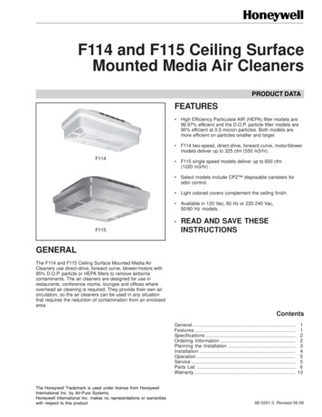
6Connecting The Drain Pipe6.1 Installation of drain pipingInstall the drain piping as shown in figure belowand take measures against condensation.Use PVC pipe, use of plastic, flexible piping isdiscouraged.3 5ftHanging bar11/100 gradient2341 - Drain socket (attached to the unit)2 - Metal clamp3 - Drain hose4 - Insulation (field supply)Fig 6.16.3 How to perform piping Keep pipe size equal to or greater than that ofthe discharge pipe of the unit. Push the drain hose as far as possible overthe drain socket, and tighten the metal clampsecurely. Insulate the drain hose inside the building. If the drain hose cannot be sufficiently set ona slope, fit the hose with drain lift piping (fieldsupply). Make sure that heat insulation work isexecuted on the Indoor drain pipe and thedrain socket to prevent condensation. Page 14 DrainhoseMetalclampDrainraising pipeHangerbracket3 5ft20.9in511.8in29.5inKeep piping as short as possible and slope itdownwards at a gradient of at least 1/100 sothat air may not remain trapped inside thepipe.8.7in Ceiling Slab0 3inConnectingThe Drain Pipe6.2 Install the drain pipesAdjustablerangeFig 6.3 Connect the drain hose to drain lift pipes, andinsulate them. Connect the drain hose to the drain outlet onthe indoor unit, and tighten it with the clamp.Revised 5/14/2020
CAUTION Install the drain lift pipes no higher than 21". Install the drain lift pipes at a right angle to the indoor unit and no more than 12" from the unit. To prevent air bubbles, install the drain hose level. The incline of drain hose should be no more than 3"so that the drain socket does not have towithstand additional force. To ensure a downward slope of 1:100, support the drain line every 3'. When unifying multiple drain pipes, install the pipes as shown in figure below. Selectconverging drain pipes whose gauge is suitable for the operating capacity of the unit. Do not connect the drain piping directly to sewage pipes that smell of ammonia. Theammonia in the sewage might enter the indoor unit through the drain pipes and corrode theheat exchanger.6.4 Test the drain piping0-530After the piping work is finished, check if drainageflows smoothly.3.9in2.6inUnit: mm4.2in3inT-Joint converging drain pipesFresh air intake 2.6inWater receiverConnectingThe Drain Pipe1004.2inT-Joint converging drain pipesFig 6.4Fig 6.5When electric wiring work is finished, checkdrainage flow during COOL running, explained in"Test operation".Revised 5/14/2020 Page 15
7Electrical WiringCAUTION All field wiring and components must be installed by a licensed electrician and must comply withrelevant European and national regulations. Use copper wire only. Follow the 'Wiring diagram' attached to the unit body to wire the outdoor unit, indoor units andthe remote controller. A circuit breaker capable of shutting down power supply to the entire system must be installed. Note that the operation will restart automatically if the main power supply is turned off and thenturned back on again. Be sure to ground the air conditioner. DO NOT connect the ground wire to gas pipes, water pipes, lightning rods, or telephone groundwires. Gas pipes: might cause explosions or fire if gas leaks. Water pipes: no grounding effect if hard vinyl piping is used. Telephone ground wires or lightning rods: might cause abnormally high electric potential in theground during lightning storms.ElectricalWiringHow to connect wiring Remove the control box lid of theindoor unit. Remove the cover of the outdoor unit. Follow the "Wiring diagram label"attached to the indoor unit's controlbox lid to wire the outdoor unit, indoorunit and the remote control. Securelyfix the wires with a field suppliedchamp. 1234612345675Attach the cover of the outdoor unit.7Control box lidWiring diagram labelPower supply terminal blockClamp for wiringWiring between unitsPlastic coverClamp (field supply)Fig 7.1PowerModelPhaseFrequencyand voltCircuit breaker/Fuse(A)12K 18K1Phase208-240V20/16 Page 16 Revised 5/14/2020
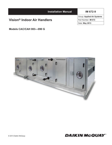
8Decorative Panel InstallationDetach the intake grilleAfter installing the decoration panel, ensure thatthere is no space between the unit body anddecoration panel. Otherwise air may leak throughthe gap and cause dewdrop. See figure below.Slide the 2 grille hooks toward themiddle of the decoration panel.1 - Intake grille12 - Grille hook2Fig 8.1Open the intakegrille and removeFig 8.4Mount the intake grilleEnsure that the grille isproperly seated in thegroove of the panel.Fig 8.2Install the decoration panel Align the indicate " " on the decoration panelto the indicate " " on the unit . Attach the decoration panel to the unit withthe supplied screws as shown in figure below.10-core wireConnect the 2 wiresof the decorationpanel to the mainboard of the unit.Leave third wire plugdetached.5-core wireFig 8.6121 - Decoration panel2 - Screws (M5) (supplied with the panel)Revised 5/14/2020Fasten the control boxlid with 2 screws.Decorative PanelInstallationFig 8.3Fig 8.7Close the intakegrille, and close the2 grille hooks.Fig 8.8 Page 17
Install Outdoor Unit(see separate manual)When you have finished installing all indoor air handlers, proceed to installation of the outdoor unit.Complete installation instructions and startup procedures are given in the outdoor unit installationmanual. Copies are always available at AlpineHomeAir.com by searching your unit's model numberand scrolling to Documents.The design and specifications are subject to change withoutprior notice for product improvement.AlpineHomeAir.comRevised 5/14/2020
Accessories Revised 5/14/2020 Page 7 Accessories 3 The air conditioning system includes the following accessories. Use all of the installation parts and accessories to install the air conditioner.